Week 9 - Attachment Feature Creation - Challenge 2
AIM: To Create the screw boss and Dog House for the Centre console coin holder considering the design rules mentioned.
Draft:
Draft is an angular tapering given at the design stage to every Plastic Component that has to be manufactured. It is given in the direction of the Mold Movement. The Draft allows the parts to release easily from the mold without creating friction between the surface of component and the core and cavity plates.
When a Plastic component cools down inside the mold, the natural tendency of it is to shrink and attach to the core or cavity half. The movement of mold opening causes friction on the walls of the component as well as the core/cavity blocks. This reduces the life of the mold as well as the component itself. The component may also have rough surface finish as well as weak structure due to this. This problem can be solved by giving draft to the component.
Most applications require minimum draft angles of around 0.5° to 1°, however 3° draft angles are widely accepted for cost saving purpose. 7° Draft angles are given to textured surfaces like Instrument Panels. Minimum possible draft angles are given to screw bosses ribs and stiffeners due to their critical nature.
Draft Analysis:
The Draft Analysis command enables you to detect if the part you drafted will be easily removed from the mould. This type of analysis is performed based on color ranges identifying zones on the analyzed element where the deviation from the draft direction at any point, corresponds to specified values of angles along a defined draft direction using colour codes. It highlights the regions of draft using colours. . Draft analysis is the first step performed after receiving the Class A of the component.
Tooling Axis:
The direction in which the mold or core and cavity opens is the tooling axis. Part Drafts are designed along this axis.
Class-A Surface:
In automotive design, a class A surface is any of a set of free form surfaces of high efficiency and quality. It is the visible aesthetic surface of any automotive component.
Draft Analysis on COIN HOLDER :
1) Check the class-A surface :
Check the Class-A surface for any discontinuities in the surface using join operation, boundray operation and disassembly operation.
2)Creating Tooling Axis:
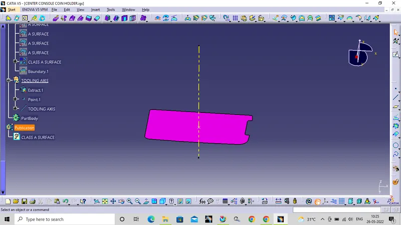
In this case walls of the coin holder has 0 degree angle so the tooling axis will be normal to the surface of coin holder.
To create the tooling axis extract the flat face of the coin holder create the point at the center of the surface, using line command create a line normal to the surface.
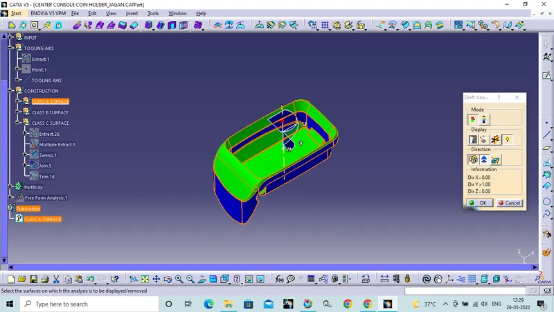
Performing draft analysis on class A surface using tooling axis which we are created before.
 .
.
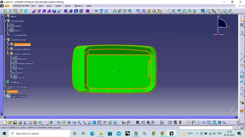
Result: Most of the faces having 0 degree angle which are not cleared with the tooling axis are in blue colour and the faces which are in green colour are cleared with tooling axis.
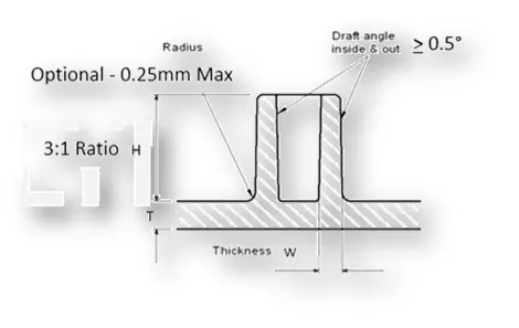
General Guidelines for Bosses:
- Draft - 0.5 degrees on walls of boss
- Thickness - Typically 40%* of the nominal wall at the base.
- Height to Diameter Ratio - 3:1
- Radii - 0.25mm maximum radii.
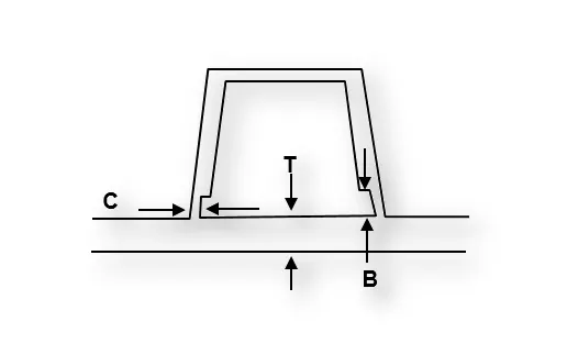
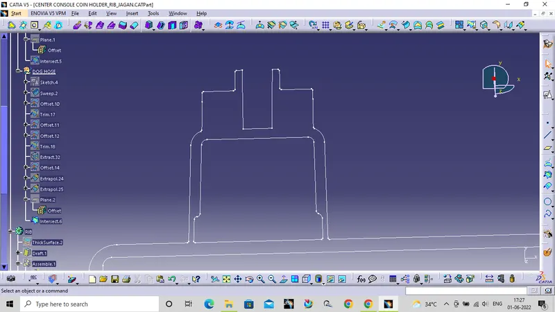
"C" is where the doghouse contacts the backside of the surface
-
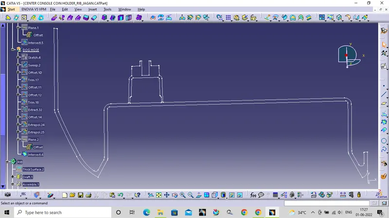
Doghouse wall thickness at the intersection of the part wall ( C ) should be 40% or less than the main wall stock ( T ).
-
Height of ( B ) should be between 3.0 – 6.0 mm
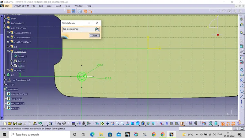
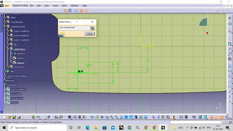
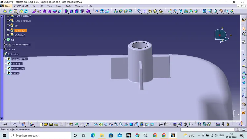
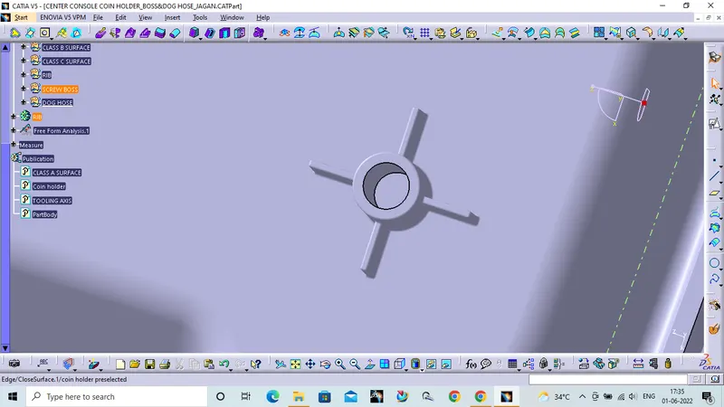
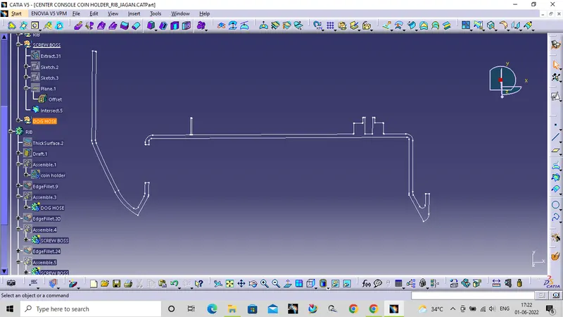
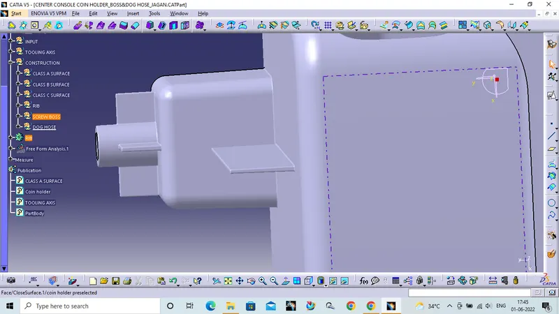
SCREW BOSS:
Creating screw boss as per the design rules.
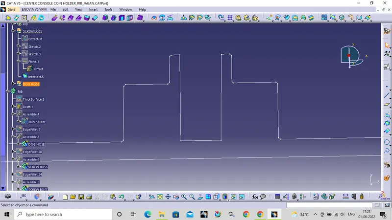
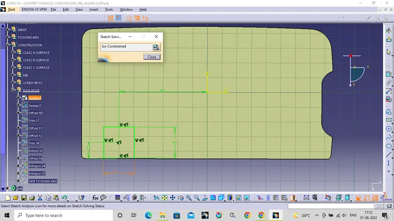
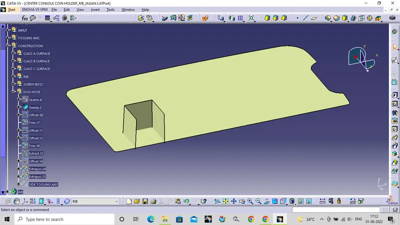
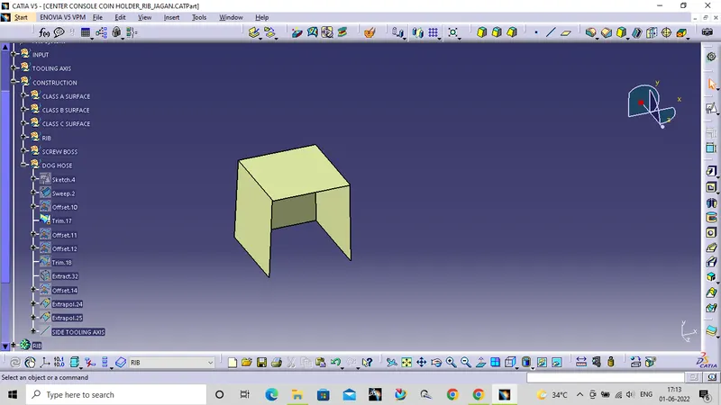
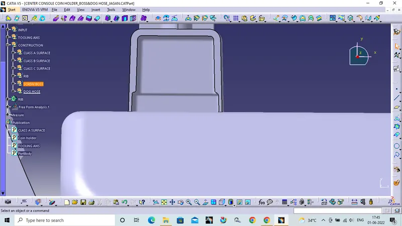
DOG HOUSE:
Creating dog house by following design rules.
SIDE CORE TOOLING AXIS:
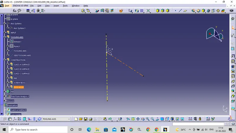
To clear the dog house we need side core tooling axis. To create side core tooling axis use line command to create a line in point-direction in z direction name it as side core tooling axis.
DREAFT ANALYSIS FOR COMPONENT:
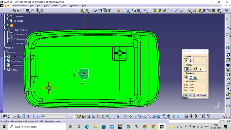
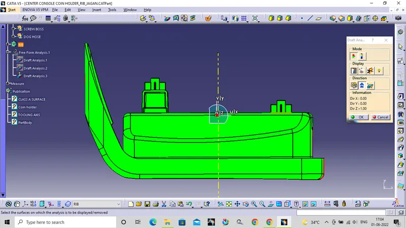
Draft analysis using side core tooling axis: