Week 9 - Attachment Feature Creation - Challenge 2
COIN HOLDER CENTRAL CONSOLE SCREW BOSS AND DOGHOUSE DESIGN
The Class A surface is provided to us. We need to create B Surface and C Surface and create a solid model. At the end we have to do draft analysis to check whether the component is manufacturable or not.
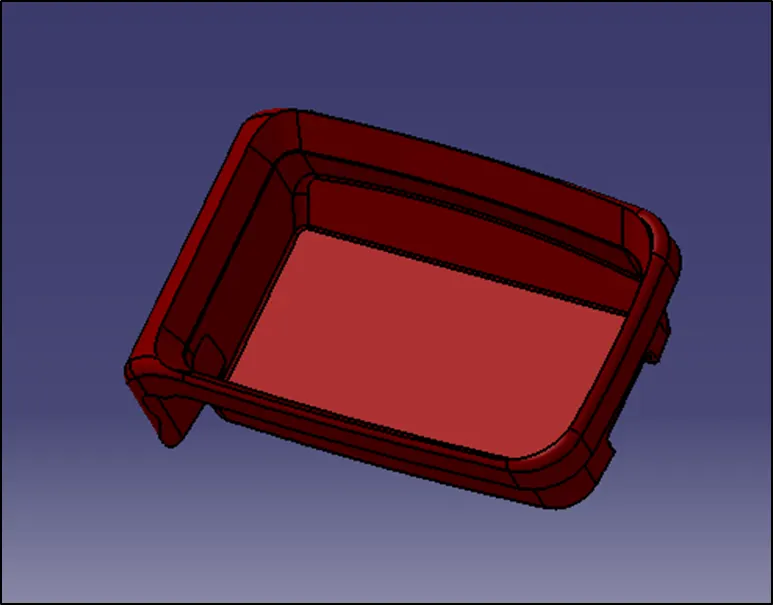
Fig 1. Class A Surface
First of all we need to check whether the surface provided has any discontinuity in it. For that we will use the command boundary and check if there is any discontinuity in the surface.
After that we will join the whole surfaces by using join command.
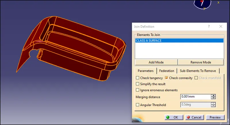
Fig 2. Join Command
Then we will randomly select the tooling axis. For making the selection first analyse the shape of the product and avoid side cores as far as possible. Here we will take the Y axis as the tooling direction and mark a point there and create a datum axis at that point. Take the intersect of the surface and the YZ component. We observe that there are flat surfaces, so we take a mean line in the direction of Y axis as the tooling direction. The flat surfaces cannot be changed by us. We need to take it to the styling team to create it with some draft so that it can easily clear the tooling. There is a hole in the side face so it will not get cleared in the Y direction tooling axis. So a side core tooling axis is required.
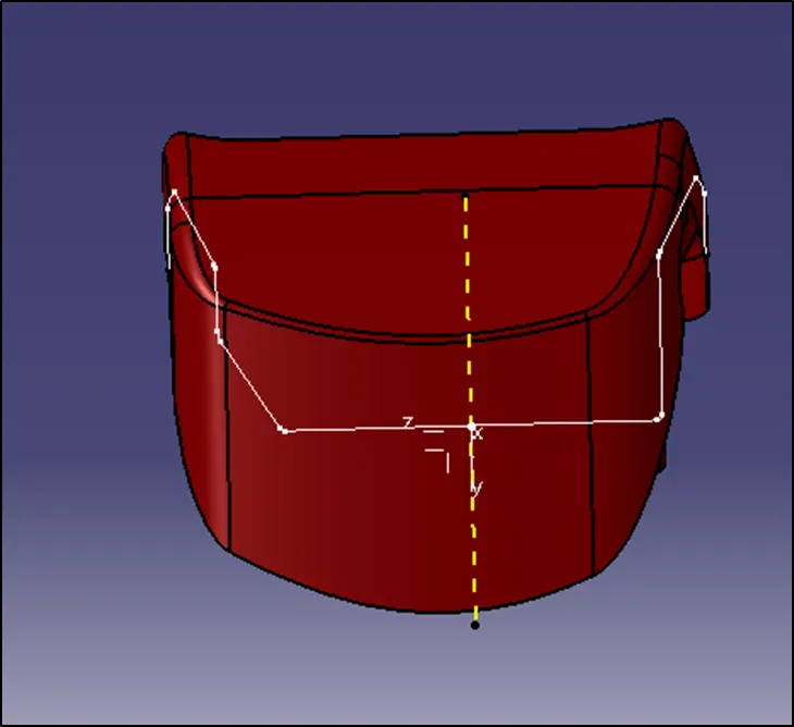
Fig 3. Tooling Axis
Now we have to perform the draft analysis in the required tooling direction.
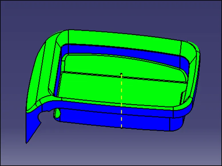
Fig 4. Draft analysis in the tooling direction
When there are inner and outer holes or undercuts on the plastic part that are different from the mold opening direction usually a side core is used. Here also to clear the ribs we need to have a side core. So side core tooling axis is created and draft analysis is done in that direction.
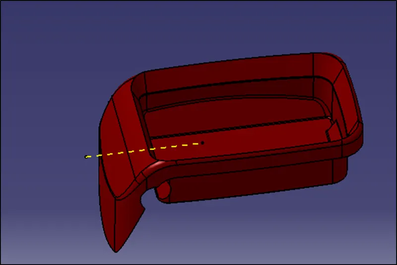
Fig 5. Side Core Tooling Axis
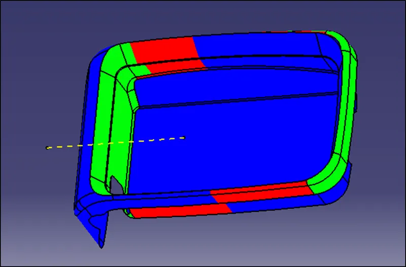
Fig 6. Draft analysis along the Side Core Tooling Axis
Now we have to create B Surface which is the Engineering Surface. All the features like holes embosses are created on the B Surface. For that we have to extract A surfaces, extend it and then trim it and apply the required fillets.
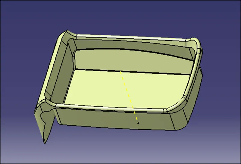
Fig 7. Class B Surfaces
Then we have to create C Surface. C surface is the surface which joins the A Surface with the B Surface. Extract the boundary of the A surface and sweep it in 90 degree with reference to the surface. Join both A and C Surface.
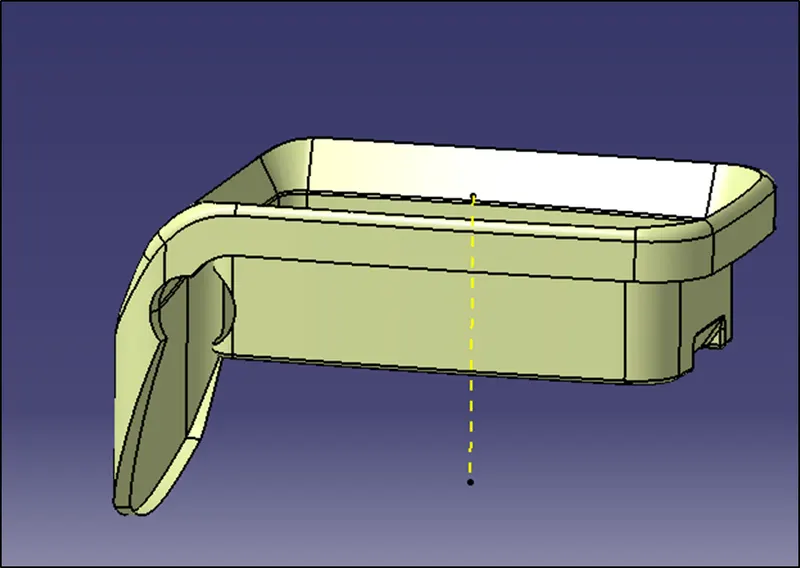
Fig 8. Class A + C Surface
Trim both the A + C Surface with the class B Surface. Then by using close surface command from the part workbench, turn the component into a Solid.
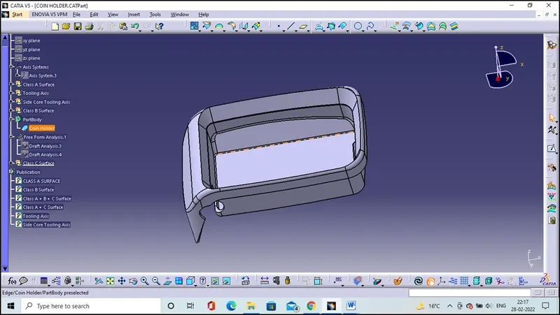
Fig 9. Solid Component
Draft analysis for the solid model on the tooling axis:
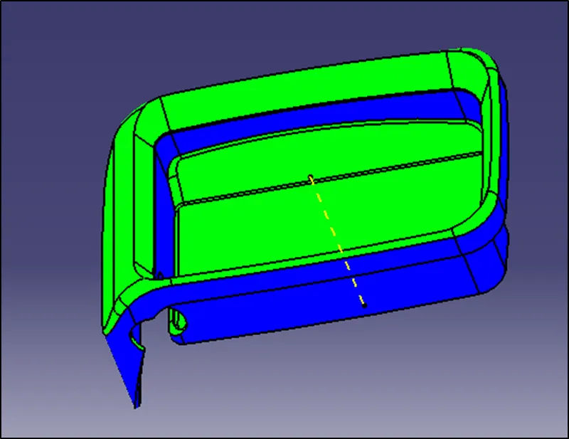
Fig 10. Draft analysis of the solid component along the Tooling Axis
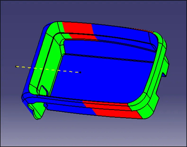
Fig 11. Draft analysis of the solid component along the Side Core Tooling Axis
Some of the views of the solid model:
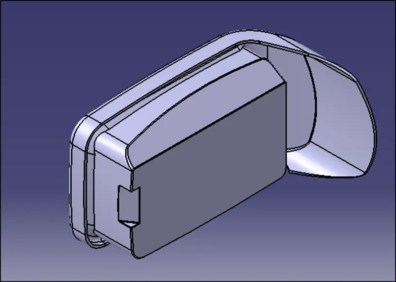
Fig 12. Isometric View
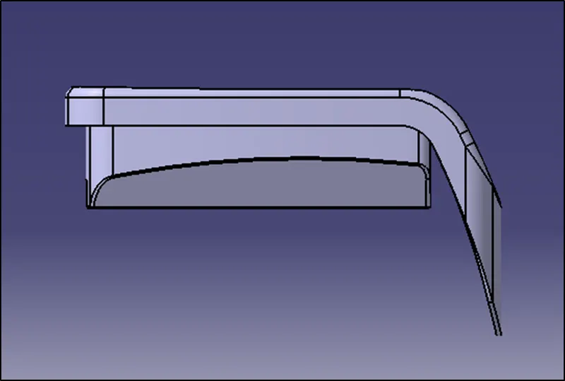
Fig 12. Side View
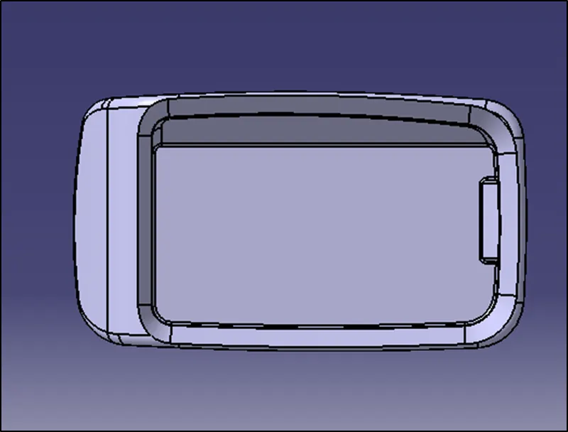
Fig 13. Top View
RIB DESIGN:
Ribs are a feature in plastic injection molded parts. They are thin extensions that run perpendicular from a wall or plane. They are commonly used to provide additional support and strength to a part. Thickness and location are essential to rib design.
Important Design Considerations while designing a rib:
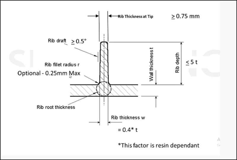
Fig 14. Design considerations for Rib Design
The rib thickness should be 0.4T (thickness of the component) i.e 0.4 x 2.5 = 1mm.
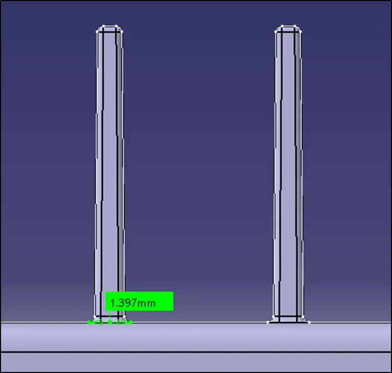
Fig 15. Thickness of the Rib
The height of the rib should be < 5T = 5 x 2.5 = 12.5. Here it is coming out be 10mm which is less than 12.5 so it will do.
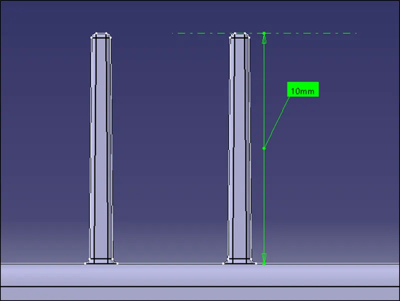
Fig 16. Rib Height
The rib thickness at tip should be > 0.75.
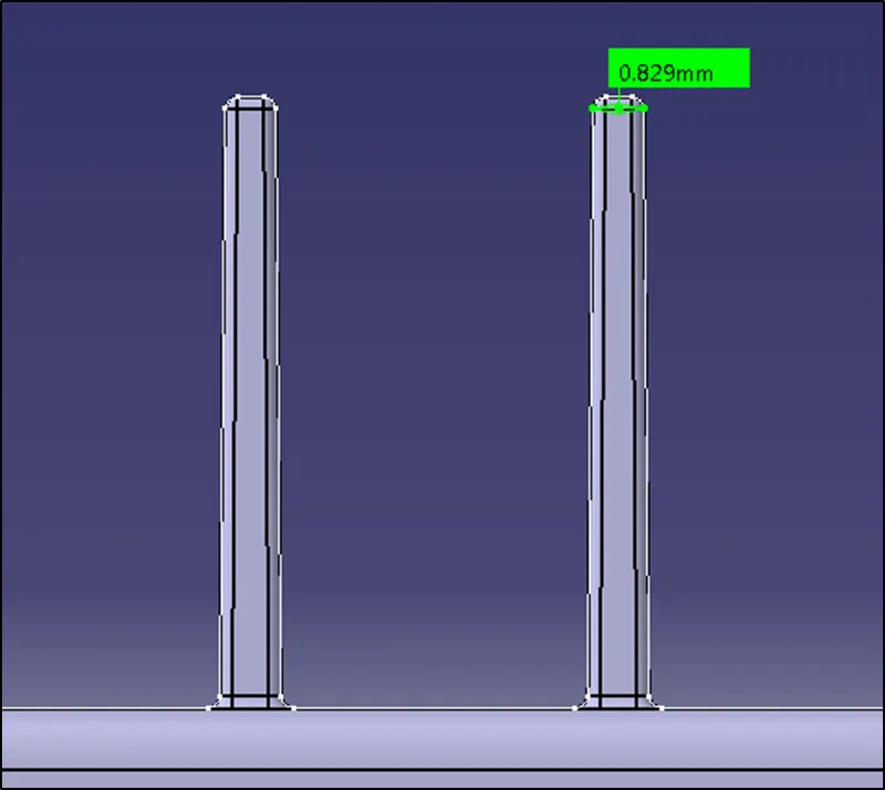
Fig 17. Rib thickness at top
The fillet radius should be max 0.25.
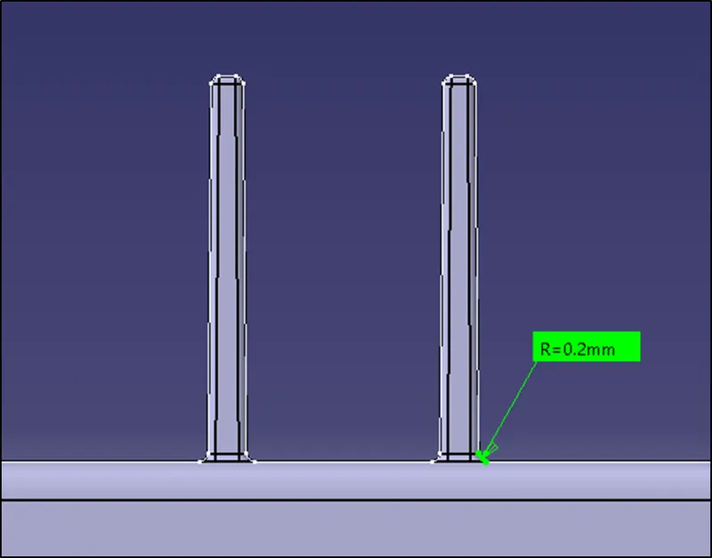
Fig 18. Fillet Radius
The rib root thickness should be +-30% of the component thickness. The rib root thickness is calculated by drawing a circle which is tanget to all the sides and then measuring the diameter of the circle. Here the dia of the circle is 2.6mm and the thickness of the component is 2.5mm. So the 2.6mm is within the permissible limit of +-30% of the component thickness.
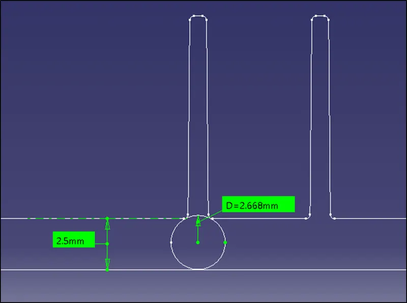
Fig 19. Rib Root Thickness
Now to find the spacing between the two ribs. The height to space between the ribs ratio should be 3:1. Here the height is 10mm and the space to be find out. By calculating we will get 3.3mm. The minimum distance should be 3.3mm. Here the spacing between the ribs is 5.5mm which is perfect.
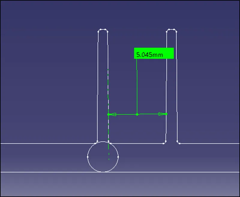
Fig 20. Spacing between the ribs
Draft analysis of the whole component:
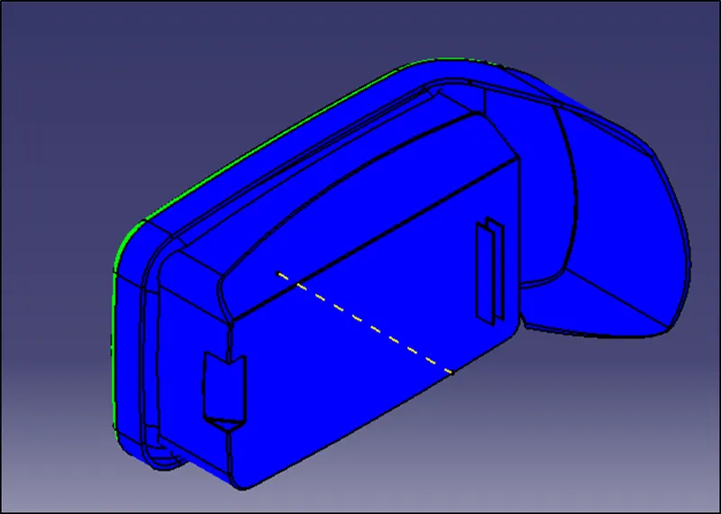
Fig 21. Draft Analysis
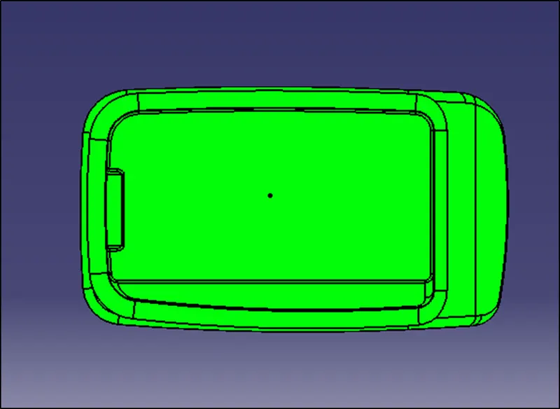
Fig 22. Draft Analysis
SCREW BOSS DESIGN:
They are used to aid in the assembly of molded parts by providing a channel for a screw. Since screw will not look good on class A surfaces so boss is given to hide the screw.
Design Considerations for screw boss design are:

Fig 23. Design Considerations for Screw Boss
In our design w = 1.47 i.e. it should be between 40% - 60% of component thickness.
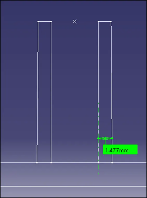
Fig 24. Width measurement
The height to diameter ratio is 3:1. The height is 15mm. The dia is 5 mm. So the height is 15mm. Since the height is large the boss becomes weak. So in order to strengthen it we provide ribs.
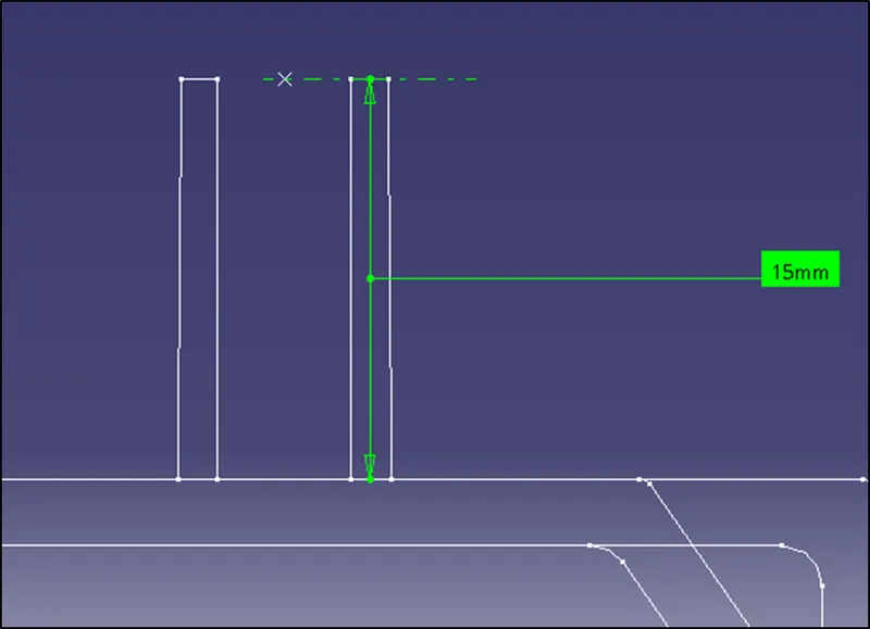
Fig 25. Height measurement
The Draft angle given is 0.5 deg.
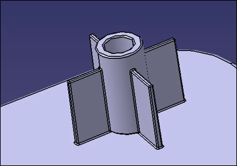
Fig 26. Screw Boss
DOG HOUSE DESIGN:
Dog house is an engineering feature used in plastic trim design. Dog houses are used as supporting feature. Sometimes other engineering features like screw bosses. are mounted on them for mating purposes and to avoid sink marks on class A surfaces.
Design considerations for dog house design are:
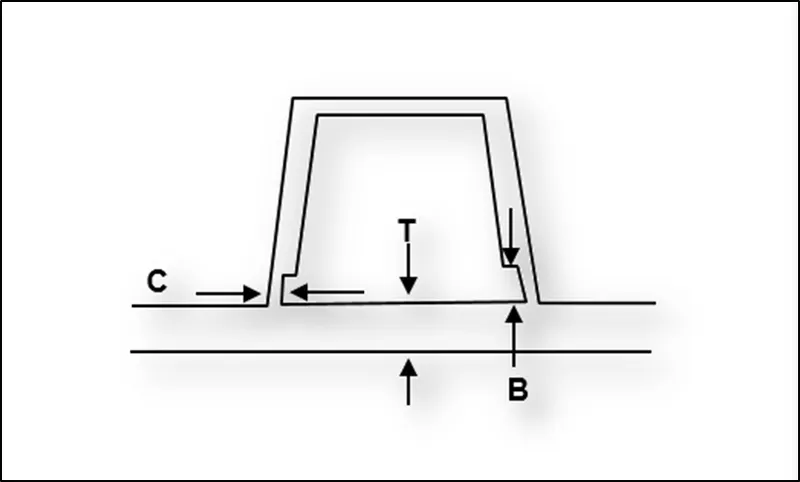
Fig 27. Doghouse Design Considerations
Here C is 1.1 which is 40% of the component thickness.
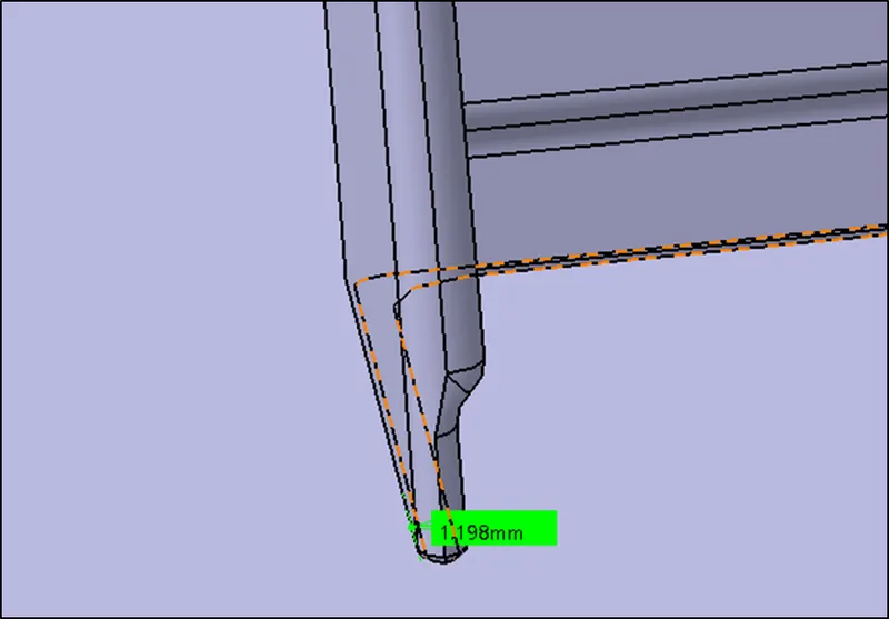
Fig 28. Measurement of C
B is 4.1mm which is between 3 to 6mm.
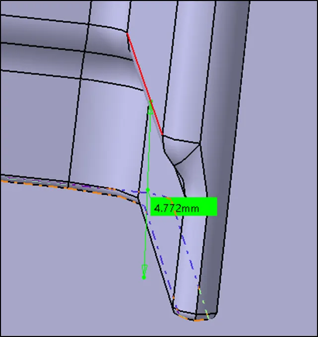
Fig 29. Measurement of B
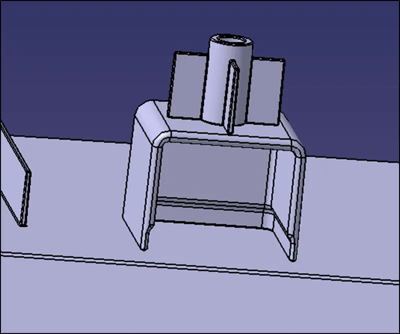
Fig 30. Doghouse Design
Draft analysis of final component:
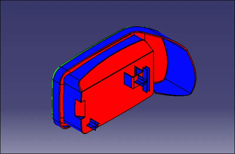
Fig 31. Draft analysis of the final component
*********