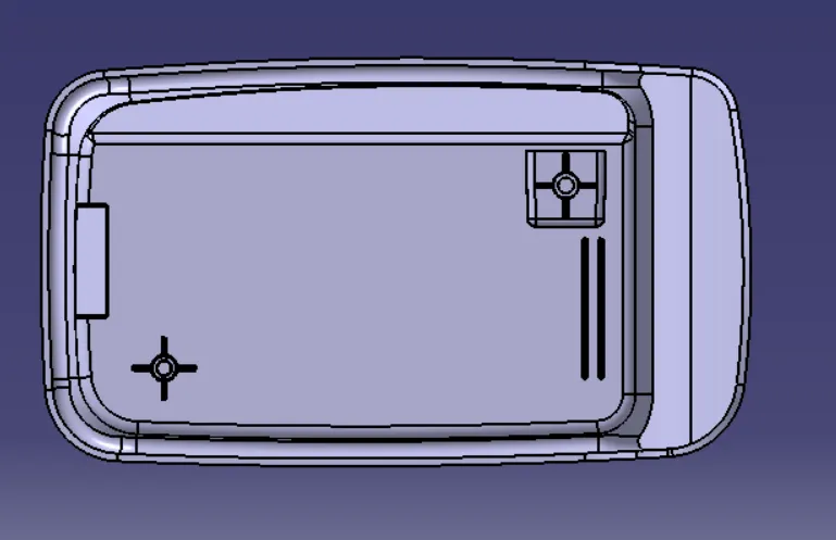
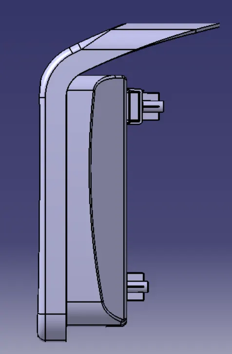
Week 9 - Attachment Feature Creation - Challenge 2
Aim
To design the engineering feature on the class B surface.
Introduction
Ribs
Ribs provide a means to economical stiffness and strength in molded parts without increasing overall wall thickness.
- They also facilitate locating and arresting components of an assembly;
- Providing alignment in mating parts
- Acting as stops or guides for mechanisms
Screw Boss
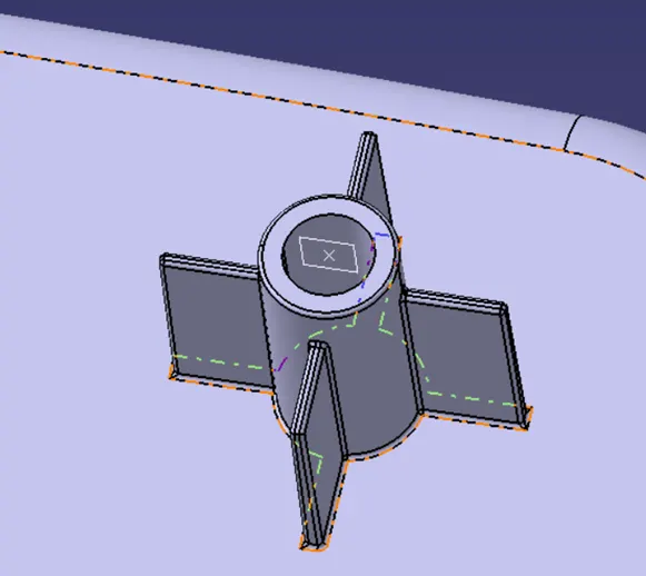
Bosses find use in many part designs as points for attachment and assembly. The most common variety consists of cylindrical projections with holes designed to receive screws, threaded inserts, or other types of fastening hardware.
Dog houses
Dog houses are used as supporting feature. Dog house is a feature that helps to avoid sink marks. They are certain locations where it is not possible to use engineering features such as locators, screw bosses etc, directly from the surface due to the desing constrains hence it is necessary to use dog house.
Procedure(All dimensions are in mm)
A) Rib Design guidelines
Nominal wall thickness of a plastic component: 3mm
A deviation of + -30% from the wall thickness is accepted Ideal draft for a component is 3 deg Minimum 0.5 deg accepted in ribs.
Example for 3 mm thickness 2.1 mm is minimum 3.9 mm maximum accepted
If we go above 3.9mm or below 2.1mm then it can lead to sink marks and at time flow lines too
Ideal draft for the components is 3 degrees
Minimum 0.5 deg accepted in ribs
For the surface where we need secondary operations for good surface finish in this area, we need to have 7-degree draft.
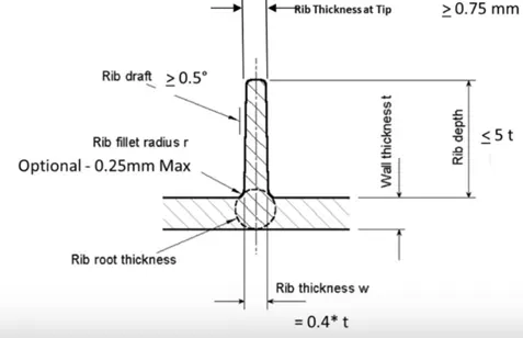
Thin - walled parts (<1.5 mm) can often tolerate ribs that are thicker than the percentages in these guidelines.
On parts with wall thicknesses that are 1.0 mm or less, the rib thickness should be equal to the wall thickness.
Rib thickness also directly affects moldability. Very thin ribs can be difficult to fill. Because of flow hesitation, thin ribs near the gate can sometimes be more difficult to fill than those further away.
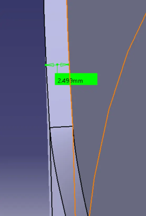
1)Thickness of the component
2)Width =2.5*0.4= 1
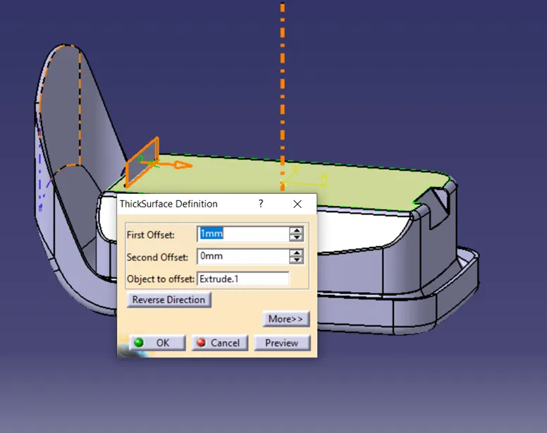
3) Height =2.5*5=12.5
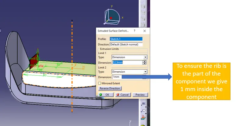
4) Draft
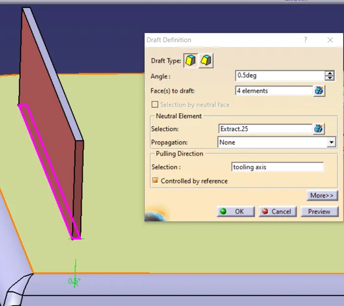
Draftes are provided so that the plastic component is manufacturable ,if the drafts are not provided the ejection of the plastic component would not be possible from the mold with damading the class A surface.
Verification
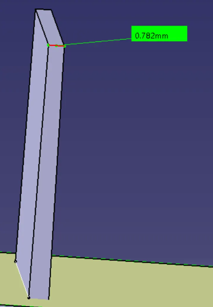
The top region of the rib is more than 0.75 hence the design is correct
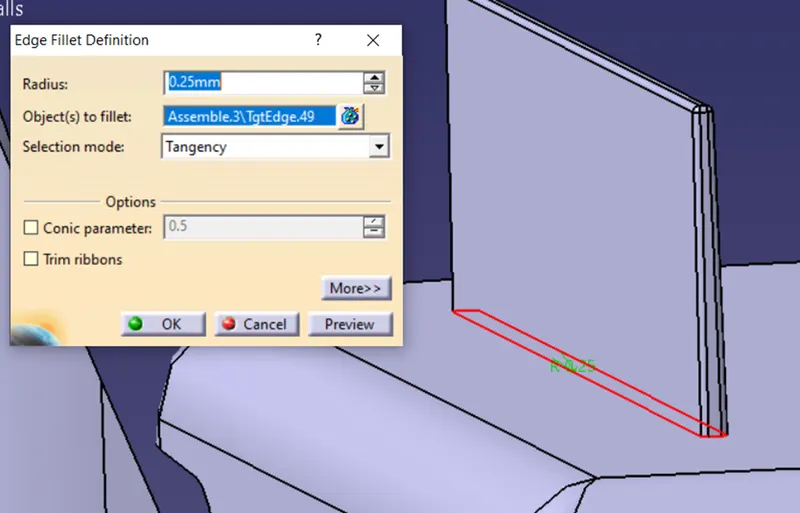
5) Fillet
Rib root thickness/ verification
We consider diameter hence 1.343*2=2.668
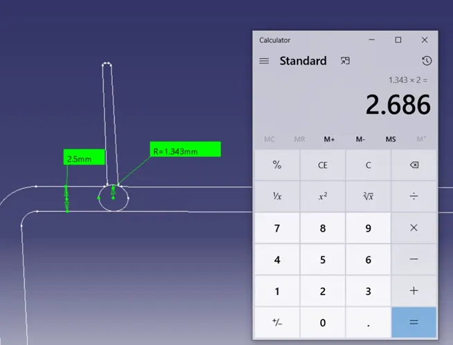
When we consider 30% deviation in the thickness so we can have 2.5*1.3= 3.25 Or 2.5*0.7=1.75
2.686 is between 1.75 and 3.25 therefore we can conclude that following these rules we can produce a component without defects.
6)Distance between two ribs
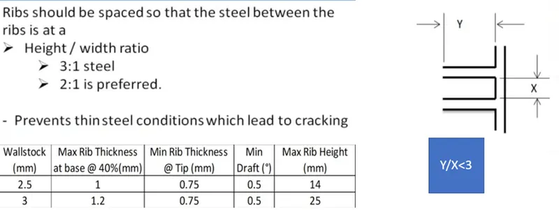
For 3:1 steel
Y=12.5
Y/X<3
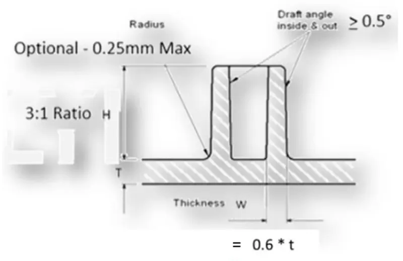
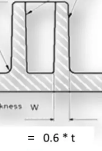
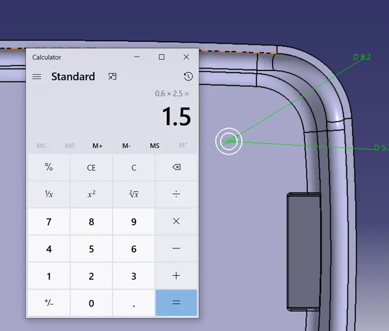
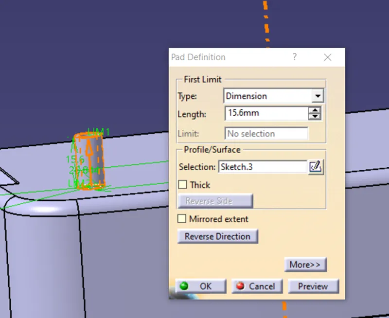
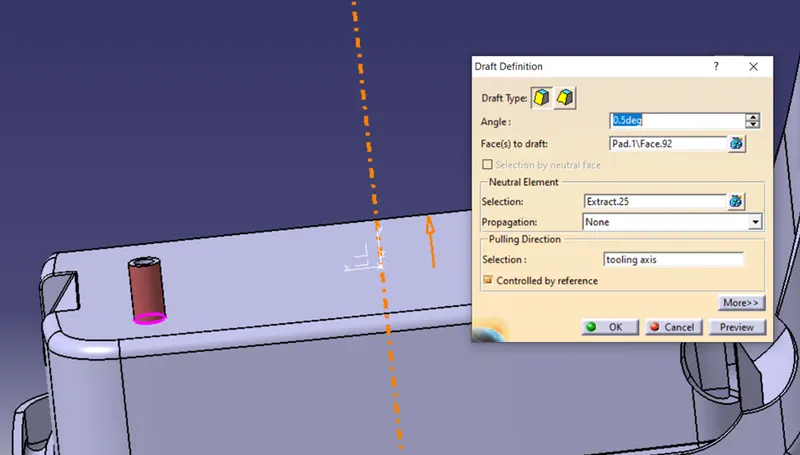
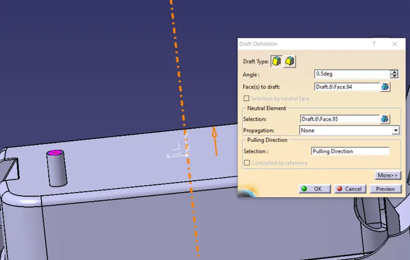
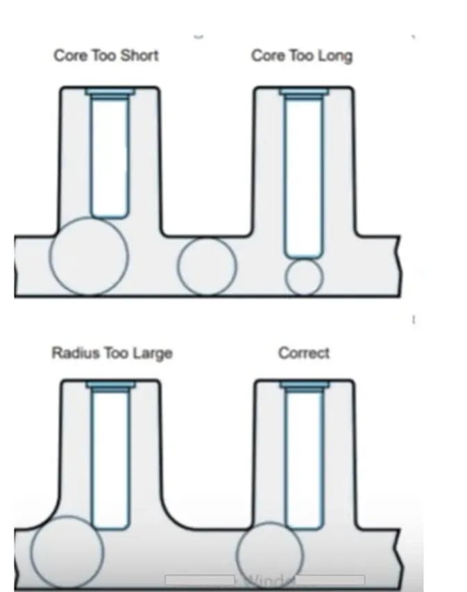
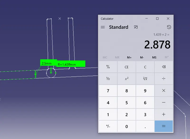
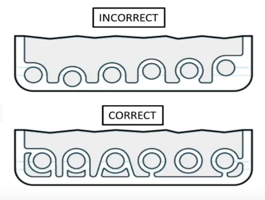
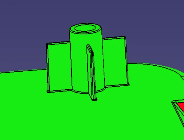
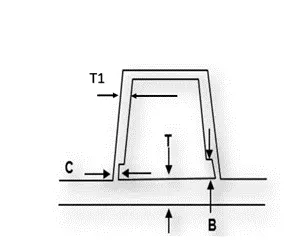
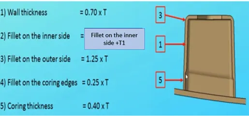
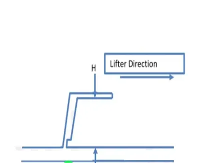
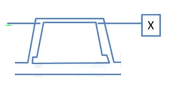
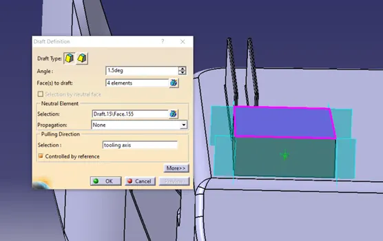
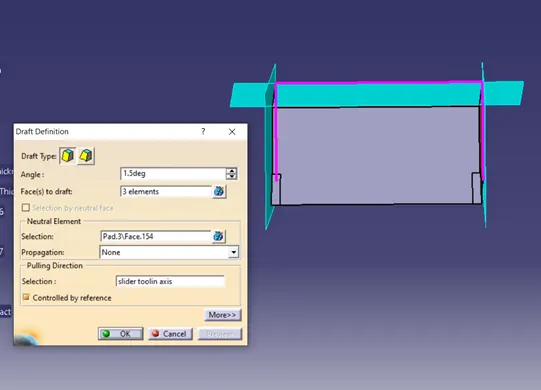
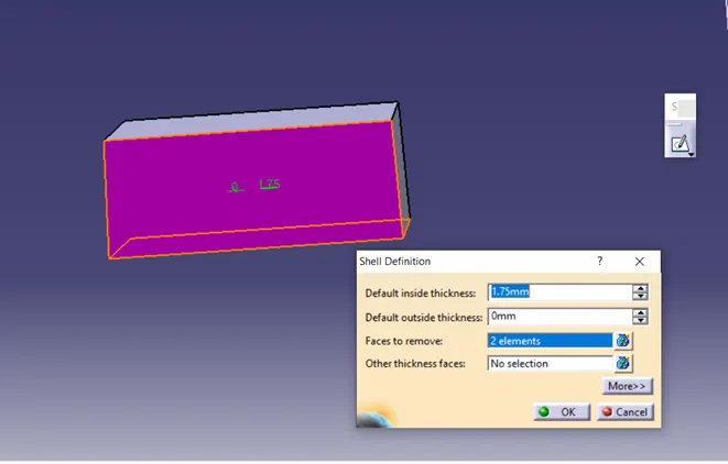
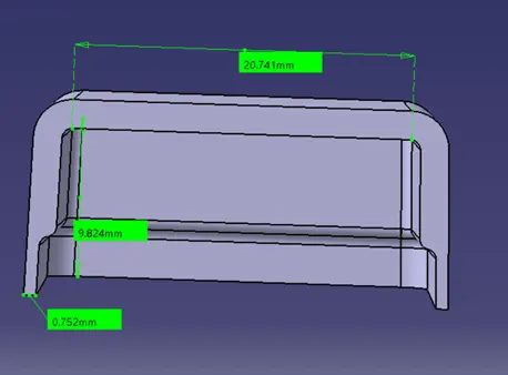
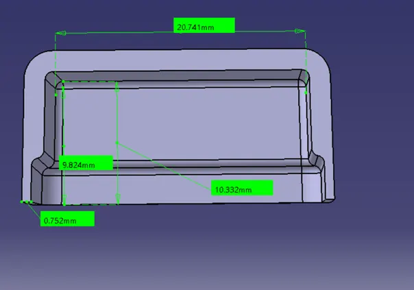
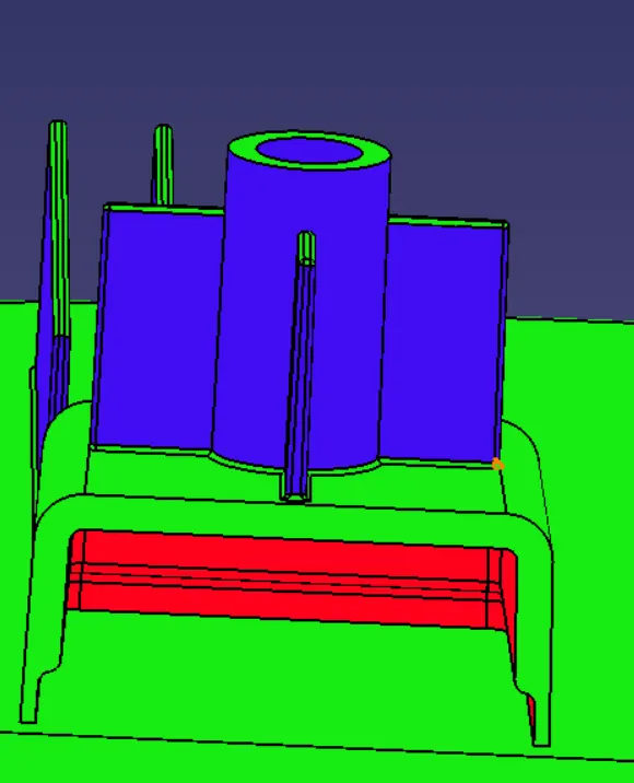
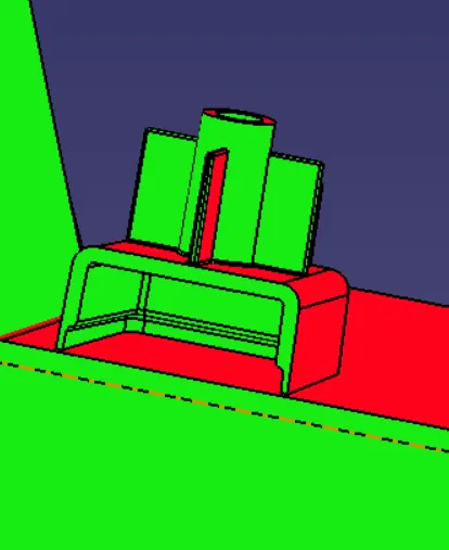
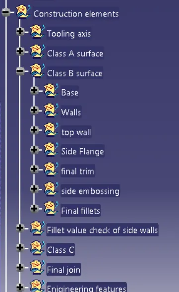
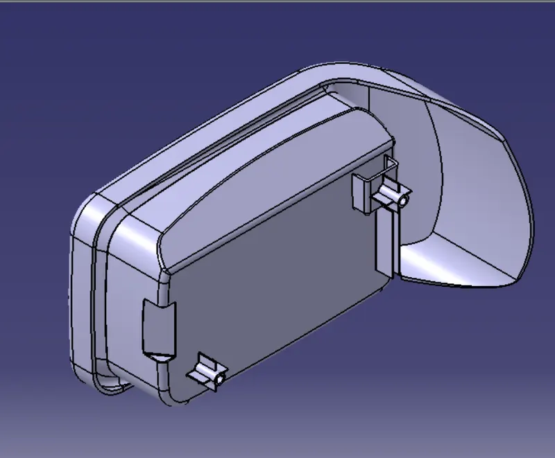
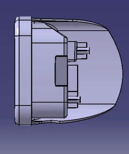
12.5/3 X=4.166 For 2:1 preferred Y/X<2 12.5/2 X=6.25 Analysis for 0.5 degree Both ribs designed can be manufactured and there is no presence of undercut. B)Screw boss design guidelines Draft 0.5 degrees on walls of boss Height to Diameter Ratio - 3: 1 (H=3*D) Radii -0.25mm maximum radii. W=0.6*t Step 1 As here M6 screw is been used i will be providing 5.2 diameter for the hole We know that W=0.6*t, which is W=0.6*2.5 =1.5 1.5*2=3 Therefore 5.2+3=8.2 Step 2 Height to Diameter Ratio - 3: 1 (H=3*D) H=3*5.2=15.6 Step 3 Draft 0.5 degrees on walls of boss Step 4/ verification Normally, the boss hole should extend to the level, even if the full depth is not needed for assembly. Shallower holes can leave thick sections, resulting in sink or voids. Deeper holes reduce the base wall thickness, leading to filling problems, knit lines, or surface blemishes. The goal is to maintain a uniform thickness in the attachment wall Because of the required draft, tall bosses - those greater than five times their outside diameter can create a filling problem at their top or a thick section at their base. Rib root thickness Diameter =1.439*2 =2.878 When we consider 30% deviation in the thickness, we can have 2.5*1.3= 3.25 Or 2.5*0.7=1.75(where 2.5 is the thickness of the component) 2.878 is between 1.75 and 3.25 therefore we can conclude that following these rules we can produce a component without defects. Ribs formed follow the same rule as mentioned above Avoid bosses that merge into sidewalls because they can form thick sections that lead to sink. Instead, position the bosses away from the sidewall, and if needed, use connecting ribs for support. Analysis for 0.5 degree Both ribs designed can be manufactured and there is no presence of undercut. C) Dog House Design guidelines T1=Maximum thickness of the dog house Dog house wall thickness at intersection of part wall (C) should be 40% or less than main wall stock (T). Height of (B) should be between 3.0 - 6.0 mm. Dog house draft to die Minimum draft (D) for dog houses 1.5 degree to die draw. If a slide is being considered, this requirement can change to 3 degrees minimum. Dog house height Minimum height (H) of dog house is 6mm. Less than 6mm causes weak steel condition. 3: 1 ratio of steel width to height, 2: 1 is preferred. Dog house width Minimum dog house width (X) for doghouse is 12mm. 3: 1 ratio of steel width to height, 2: 1 is preferred. Calculation Draft of 1.5degree with respect to main tooling axis Draft of 1.5degree with respect to slider tooling axis Wall thickness Wall thickness=0.7t Wall thickness= 0.7*2.5=1.75 Shell command is used Calculation of height Width is 20.679 which is greater than the minimum value 12mm Preferred value 2:1 2/1=width/height 2/1=24/height Height=20.679/2 =10.3395 is greater than the minimum value which is 6mm In the above image the minimum height is 9.824 need to be updated to 10.3395 as shown below Core calculation Height of (B) should be between 3.0 - 6.0 mm. fillets Inner fillet =0.25*t=0.25*2.5=0.625 outer fillet =0.625+1.75=2.375 core fillet 0.25*0.625 Analysis for 1.5 degree Analysis with respect to main tooling axis Analysis with respect to silder tooling axis for (1.5 degree) Tree Structure Screenshots of the completed design in various orientations Isometric Front Side Top Conclusion The engineering features were designed successfully