Week 9 - Attachment Feature Creation - Challenge 2
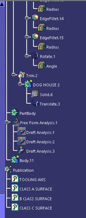
Aim: Create the Dog House for the Door Trim considering the design rules and perform the draft analysis for class A and create the final close body component and perform the draft analysis.
Objective:
- Create the Tooling axis
- Design the class-B and class-C surfaces and join them.
- Use the Close Surface feature to make a solid body from the surface.
- Design the required dog house and analysis them.
- Perform the Draft analysis for the final component.
Tooling Axis :
Class-A surface is first analyzed to create the tooling axis. where the molds pull apart in injection molding. Tooling direction is essential for plastic product design as it decides the direction for mold separation.
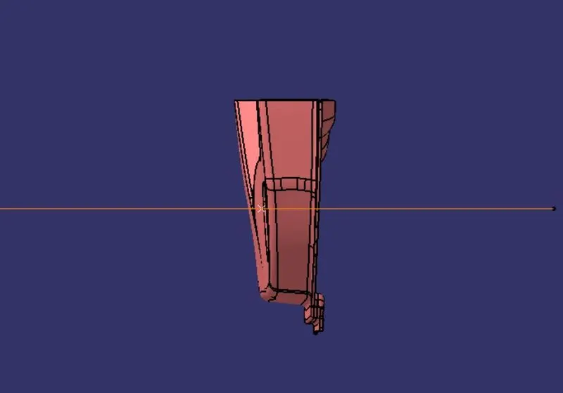
To create the tooling axis first we have to check the best suitable direction for tooling by using the compass. the y direction is suitable for creating the tooling axis because in the y direction most of the surfaces are clearing while performing draft analysis. Generally tooling axis is created using bisecting line method but here A line normal to the surface is created in the y direction and considered the tooling axis.
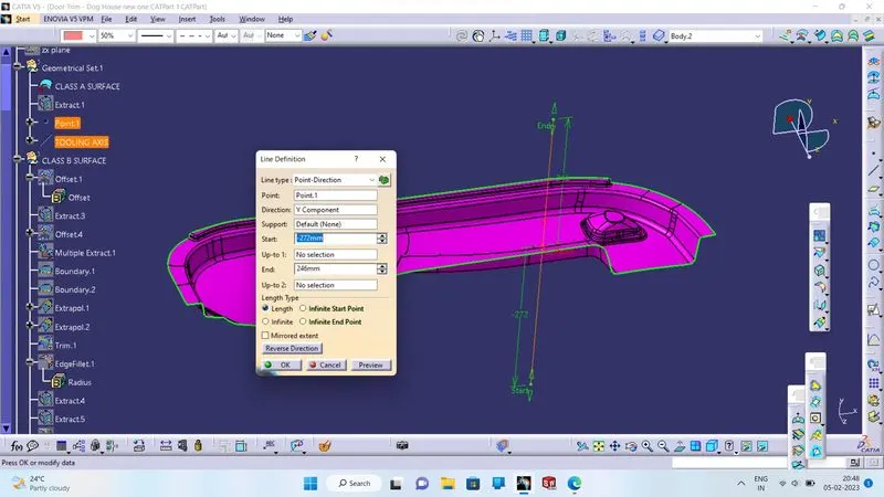
Draft Analysis: to check whether our tooling axis is proper or not we do the draft analysis.
- Go to insert > analysis > feature draft analysis.
- Align the compass with the tooling axis.
- Then, click on the Class-A surface to see if the it is within the permissible limit of the draft values.
- The Class-A surface should turn green and then draft value should be given as 2.9 degrees.
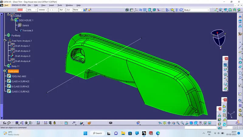
CLASS B SURFACE:
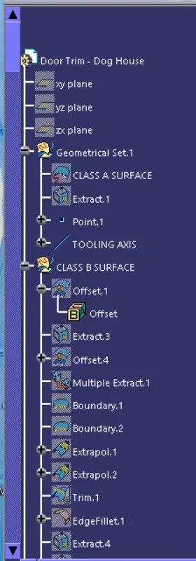
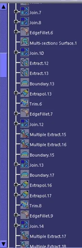
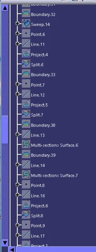
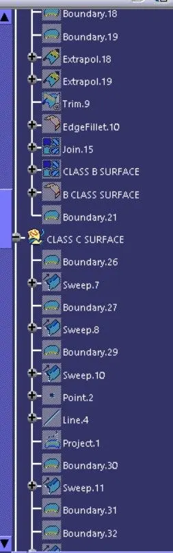
In this component Creation of the class B surface first, we have to offset the entire model by 2.5mm outward some of the surfaces give offset error and ask for offset without these subelements click okay and work on the incomplete surfaces by using the multi-section surface command, sweep and different commands used to complete the class B surface.
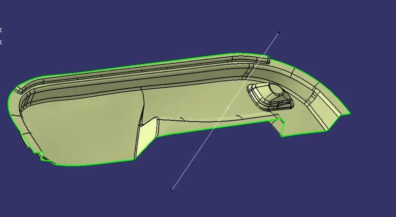
CLASS C SURFACE:
I used the sweep command in the geometric shape design workbench to create the class C surface.
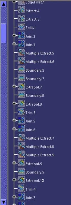
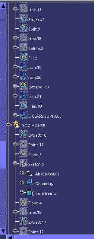
Initially, I extracted the edges of the class A surface with tangent continuity by using the multiple extract command. After extracting the class A surface edges correctly, I sweeped the extracted edges with 93deg toward the class B surface. After sweeping the extracted class A surface edges, I extrapolated the edges of the sweep for 2mm to intersect the sweep edges with each other. Now I trimmed the extrapolated surfaces together to create a complete sweep surface towards the class B surface. I joined both the trimmed sweep surface and class A surface together, to get the class A+C surfaces as a single surface. Now, to create a solid body for the door trim we need a closed surface. I trim the class B surface with joined class A+C surface to make the closed surface of a door handle.
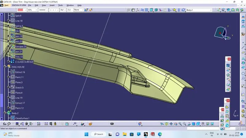
Creating a Solid body of DOOR TRIM:
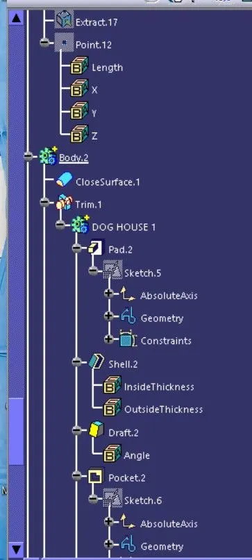
To create the solid body I used the closed surface command in the part workbench. Click on the closed surface command in the part workbench and give the closed surface as an input to create the solid part body.
DOG HOUSE DESIGN:
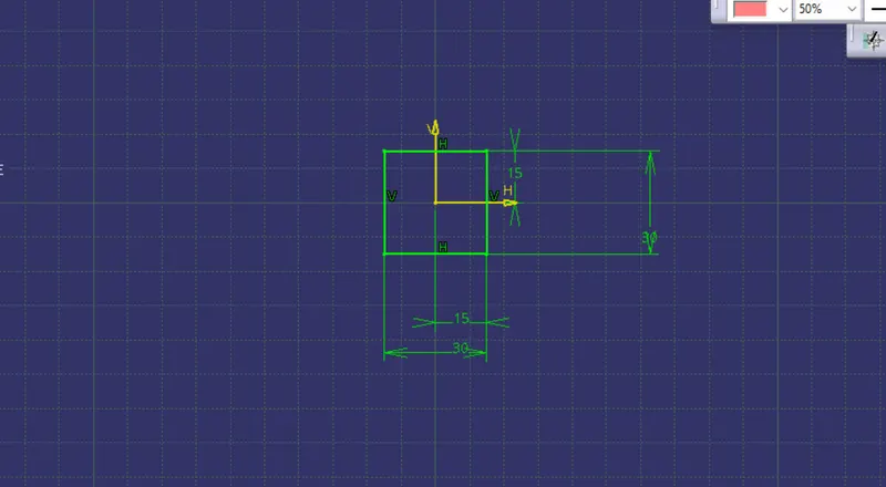
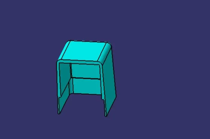
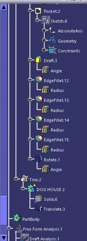
To create the Dog House we create a sketch on the XZ plane and draw a profile. After that we extrude the profile using Pad command and then translate it to obtain the second rib. We give draft of 0.5 degrees to the outer walls using the Tooling Axis and also, we create a Sliding Tooling axis by creating a line perpendicular to the tooling axis in the X-axis direction and use it as a pulling direction for giving the drafts to the inner wall of the Dog Houses.
FRONT VIEW.
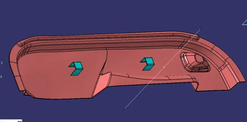
ISOMETRIC VIEW.
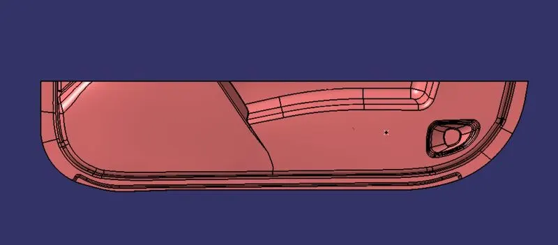
SIDE VIEW.
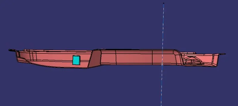
TOP VIEW.
Conclusion :
Hence, the dog house for the door trim was created by considering the design rules, and the Draft analysis performed on the final component is successfully done.
REPORT:
The faces which are not created in the draft analysis are not drafted properly while the class A surface is created.
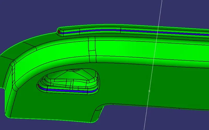
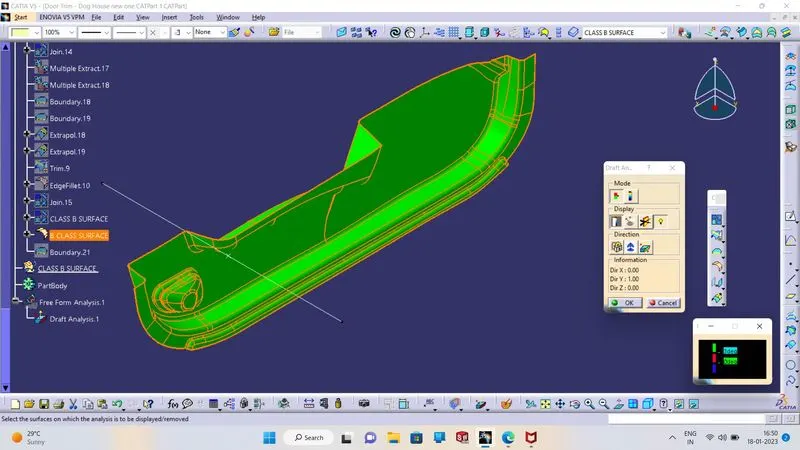
NOTE: -THE CLASS A SURFSCE IS NOT PROPER ,THATS WHY CLASS B AND CLASS C SURFACE DRAFT ANALYSIS ARE NOT DRAFTED PROPERLY.