Week 9 - Attachment Feature Creation - Challenge 2
CREATING TOOLING AXIS -
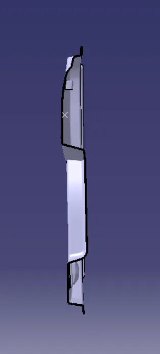
The Tooling Direction is basically the direction that the mold pulls a part. The mold is built in two separate pieces, basically. You have a Cavity side and you have the Core side. The Core pulls apart from the Cavity and that's the Dye line or the Tooling Direction
BISECTING METHOD
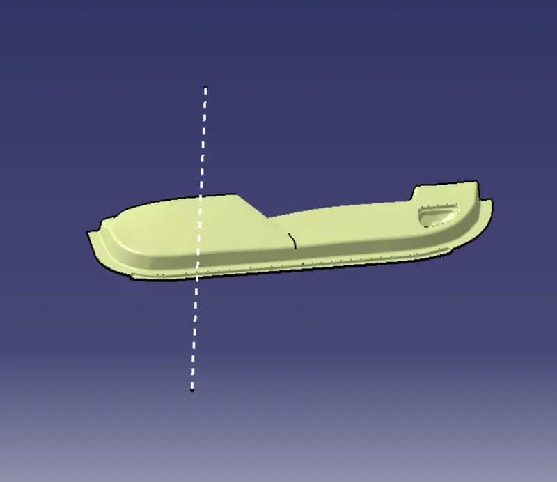
This method is used for the generation of the tooling axis for that purpose first we need to decide the direction of molding and then we create one dummy tooling axis for the reference to the purpose.
In this method, we select the surfaces which can create problems and take intersections in the x and y-direction. By using these curves we draw two lines and then draw a bisecting line from these two lines in the x-direction and y-direction.
If it is done in x-direction then it is called a tooling axis clearing x-direction and if in y then tooling axis clearing y-direction.
After completing this we need to draw a final line bisecting this two tooling axis in the X and Y directions to get our final output.
PUBLICATION
- Publication is done to the component to make it visible and navigate easily.
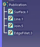
- To publish the component go to tools > publications and then select the tooling axis and the class A surface.
- A separate tree structure is formed under the main part.
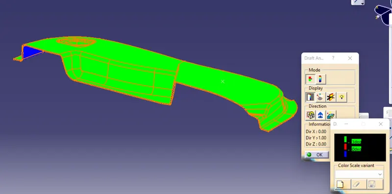
DRAFT ANALYSIS
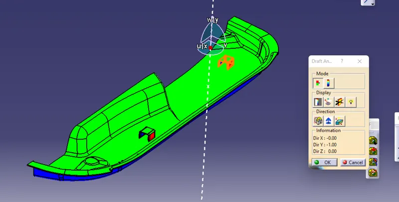
Draft angle is nothing but providing some tapered portion to the part for easy removal of the component from the mold during manufacturing. This is especially done in the case of plastic component design having a complex shape. Mostly the 3-degree draft angle is provided but it can vary depending upon the component which is to be designed
In our case of Switch Bezel design, the draft angle is 3 degrees the draft analysis is done during the design of the component to check the feasibility of the product.
Before providing a draft angle we need to decide on the tooling axis also known as the molding axis considering the faces which can cause issues while manufacturing.
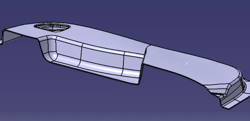
4. CREATING CLASS B SURFACE
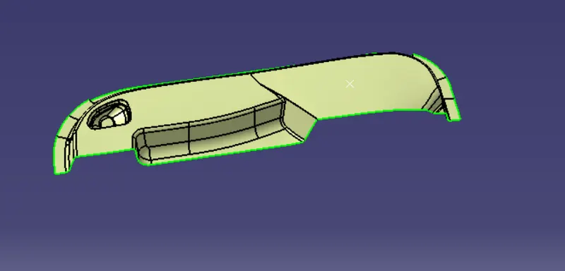
5. CREATING CLASS C SURFACE
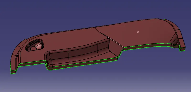
Now open part design workbench and using close body surface create a solid of the component.
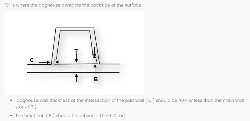
DOG HOUSE CREATION
Design Principle for Dog House Creation
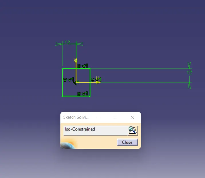
Sketch
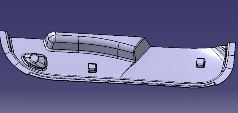
- DOG HOUSE
7. END DRAFT ANALYSIS
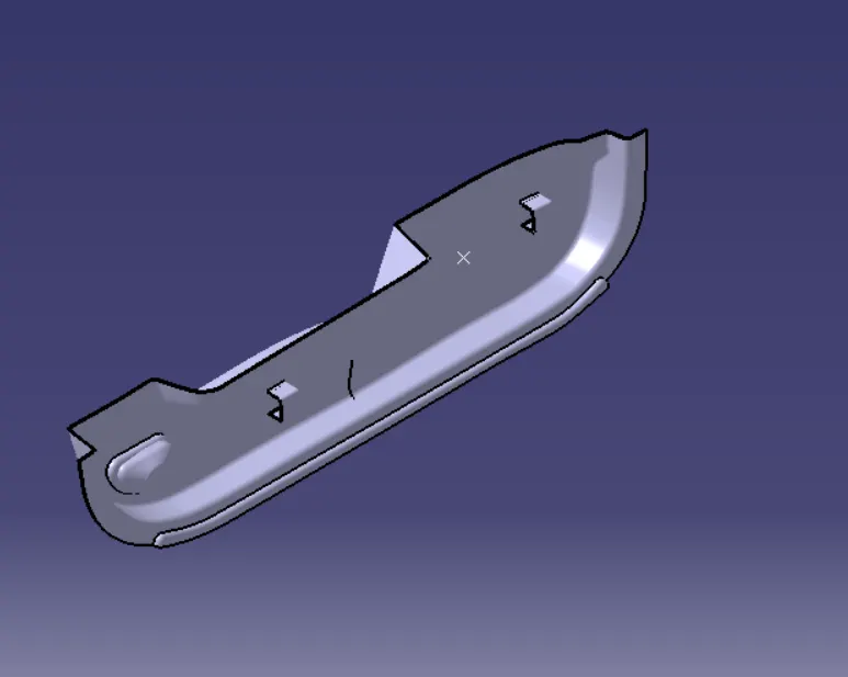
ISOMETRIC VIEW
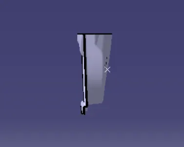
FRONT VIEW
SIDE VIEW
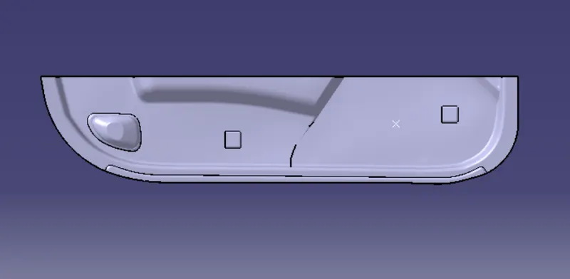
TOP VIEW