Week 9 - Attachment Feature Creation - Challenge 2
Aim: Create the boss and Dog House for the Centre console coin holder considering the design rules.
Theory:
- Class A surface: It is outermost surface of automobile which gives aesthetic look to vehicle. It is physically touchable. It is obtained from clay modeling by reverse engineering. This surface is given input to plastic product designer to work.
- Class B surface: This surface is created by taking offset from class A surface. It is surface on which all engineering feature like screw bosses, dog house, ribs & mounting are created.
Screw boss design:
Bosses find use in many part design as points for attachment & assembly. The most common variety consists of cylindrical projections with holes designed to receive screws, threaded inserts, or or other types of fastening hardware. As a rule of thumb, the outside diameter of bosses should remain within 2 to 2.4 times the outside diameter of the screw or insert.
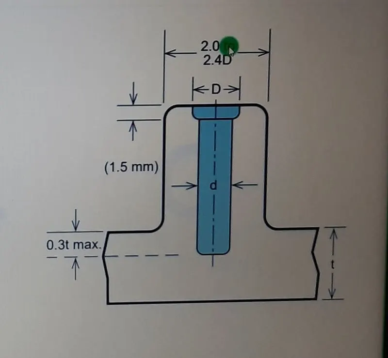
Avoid bosses that merge into side walls because they can form thick sections that lead to sink. Instead, position the bosses away from the side wall & needed use connecting ribs for support.
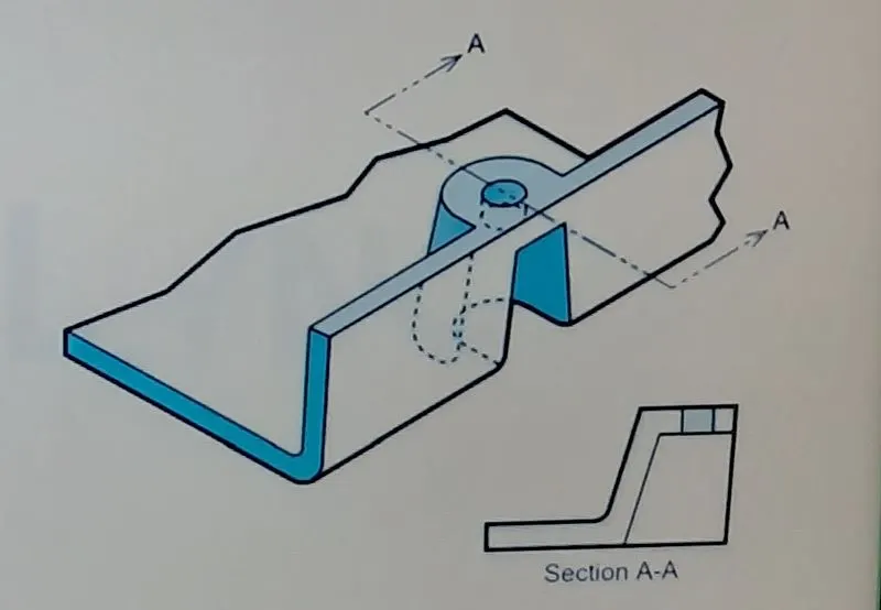
- Consider using open boss designs for bosses near a standing wall.
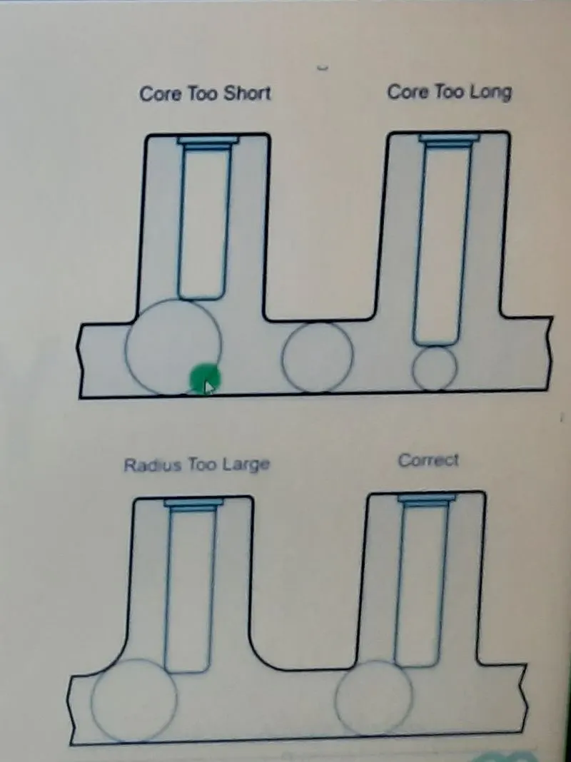
- Normally, the boss hole should extend to the base wall level, even if the full depth is not needed for assembly. Shallower holes can leave thick sections, resulting in sink or voids. Deeper holes reduces the base wall thickness, leading to filling problems, knit lines, or surface blemishes. The goal is to maintain a uniform thickness in attachment wall because of the required draft, tall bosses those greater than five times their outer diameter.
- Design rule for screw boss:
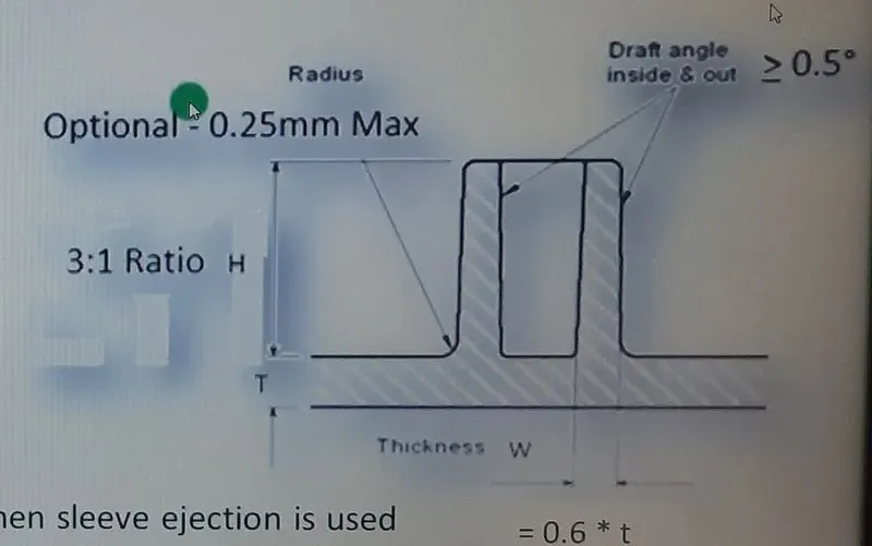
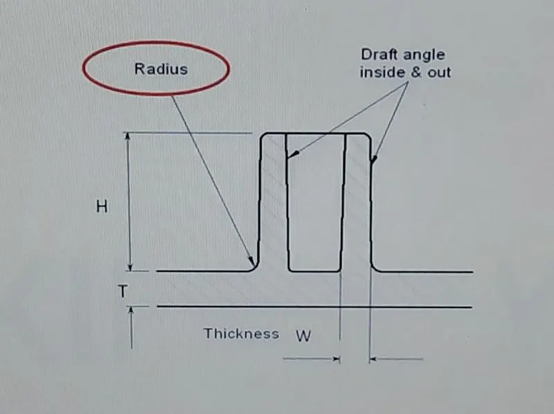
- Draft angle:
There should be minimum 0.5 degrees on both inside & outside walls of boss. Different rules if sleeve ejection is used.
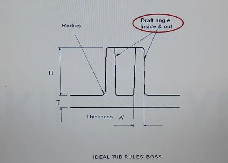
- Thickness:
W= 0.6*T
Measure base thickness of rib at tangent of radius if radii are modeled in
The larger the area at the base of the rib, the more heat retained. The retained heat causes more shrinkage, which causes sink.
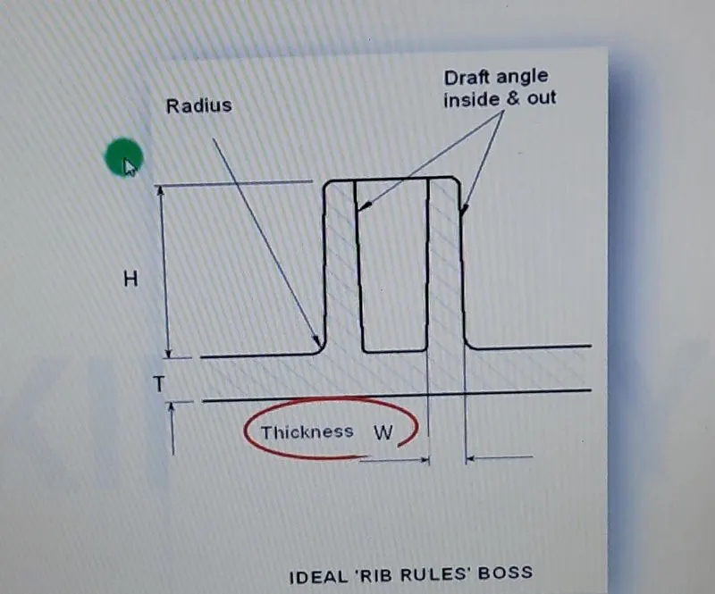
- Height to diameter ratio:
General rule,
H/B < 3
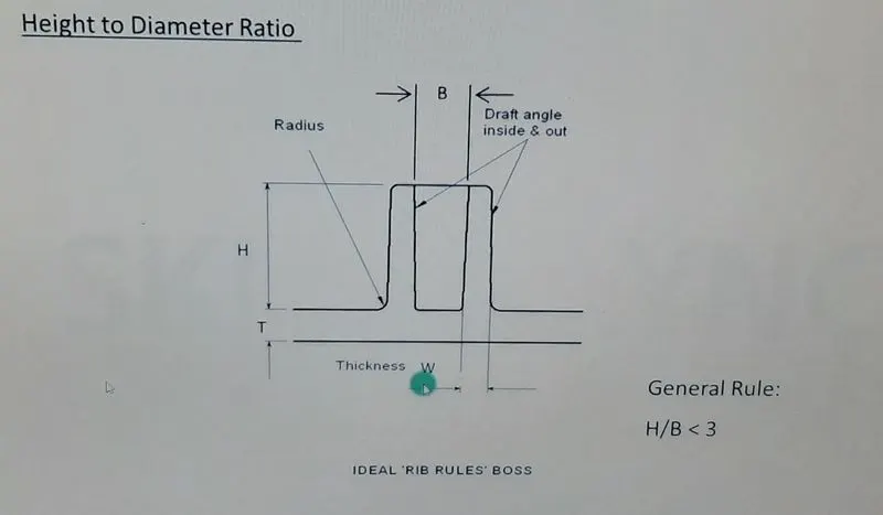
- Optional radii:
Optional rib fillet radius - 0.25 maximum. Must not violet 40% thickness requirement.
- Boss gussets:
Gussets are added to strengthen the screw boss. Boss gusset must be meet rib guideline.
- Planning ahead for type of ejection:
If less than 25 mm tall, draft is not required when sleeve ejection is used.
Over 25 mm tall draft is required on outside wall only if sleeve ejection is used.
If sleeve ejection not used, draft is required on all walls.
Design methodology:
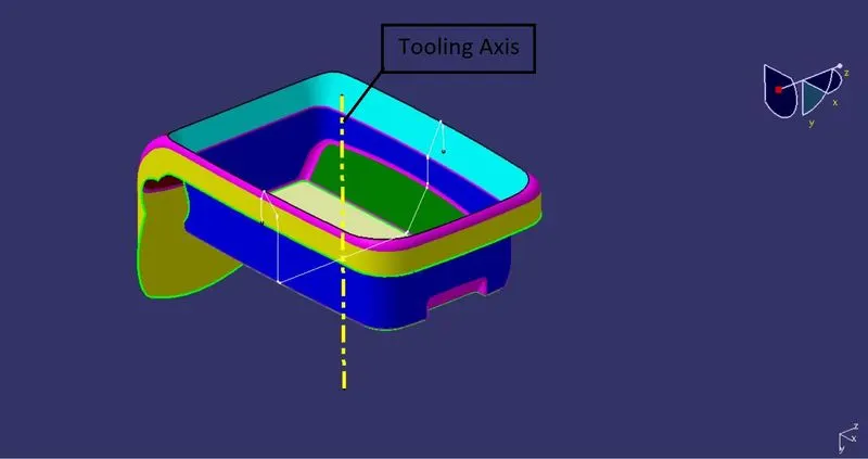
- Creating tooling axis direction:
Next step is to decide tooling axis direction. Analyzing the model to see which faces will create problem for tooling. Taking intersection of class A surface with YZ plane of axis system. Side faces hasn’t provided draft these faces will create problem during tooling. Class A surface should need to modify with draft on side faces. This can be done by class A designer. But now we proceed with same.
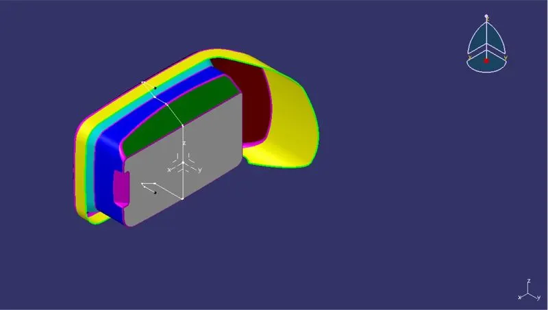
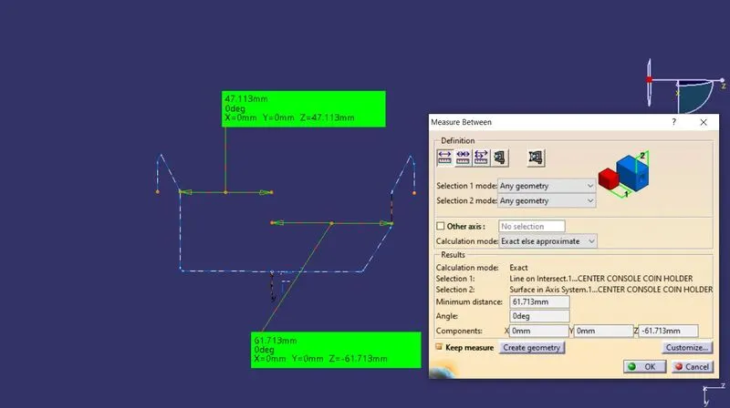
- In this case, tooling axis is normal to base surface. Consider Y axis as tooling direction. Extract the base surface. Create point on surface & creating line normal to base surface passing through that point. This is our tooling axis.
- Creating a screw boss:
Extract the bottom base surface of coin holder i.e. B side. Sketch a profile of screw boss on extracted surface. Sketch a concentric circle & dimension circle as per below.
Considering M6 screw for screw boss design. So inside hole diameter of screw boss is 5 or 5.2 mm.
As per design rule, W= 0.6*T, where t is component wall thickness
W= 0.6 x 2.5 = 1.5 mm per side.
So, outside wall dia. = 5.2 + 2 x 1.5 = 8.2 mm.
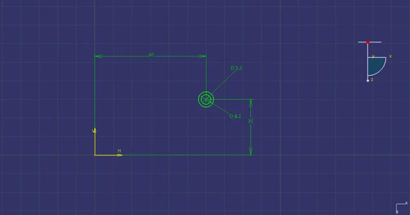
- Height of boss:
As per design rule, height to dia. ratio <3
H < 3 x 5.2 < 15.6
So consider ht. of boss = 12 mm.
So pad the sketch 12 mm in upward direction & keep 1mm in other direction to ensure there is no any gap.
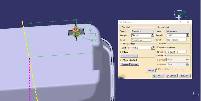
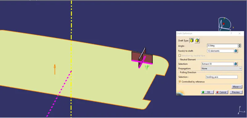
- Draft angle: Add 0.5° draft angle to the faces of screw boss.
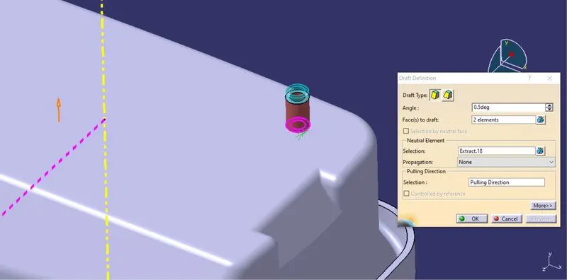
- Adding gussets to screw boss:
First make sketch profile of gussets. Then pad the sketch with thick feature. Now as per design rule for rib, thickness is 0.4*t. So keep thickness value as 1 mm & height should not be more than 5*t so keep pad value 10mm. Keep profile of sketch in middle assign thickness equal to both side.
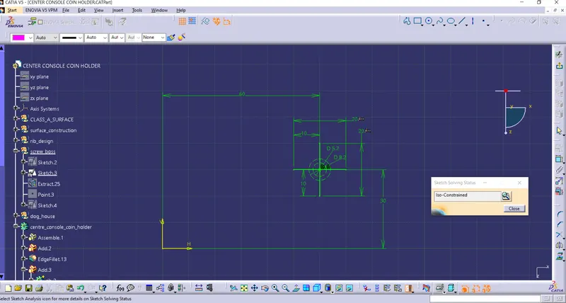
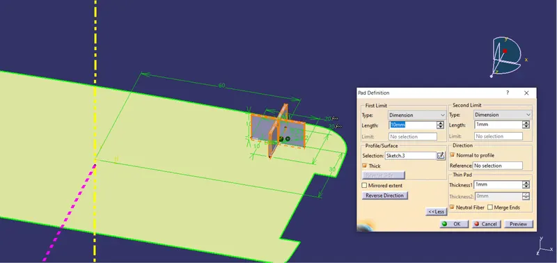
- Draft: Add 0.5° draft to all faces of gussets.
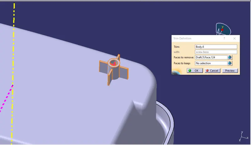
- Perform union trim with the screw boss body & then assemble screw boss to main body. Give minimum fillet of 0.25mm edges.
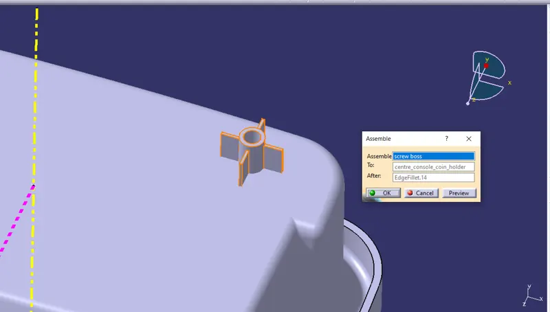
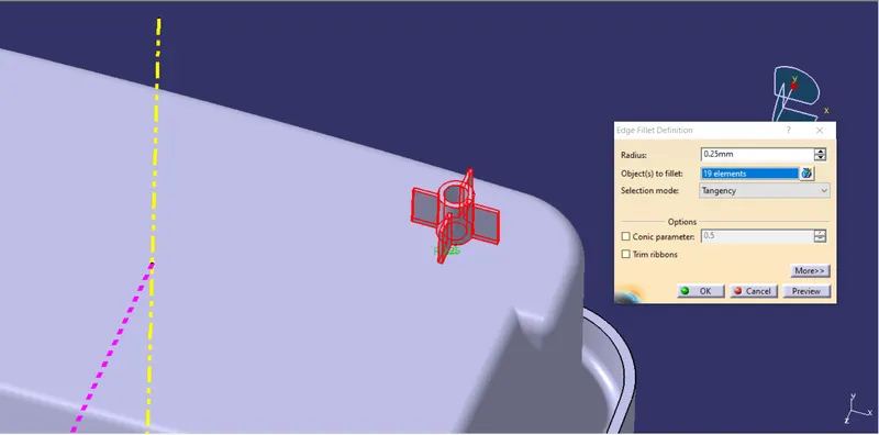
- So final screw boss be like this.
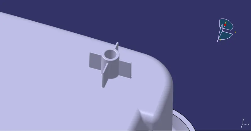
- Dog house design:
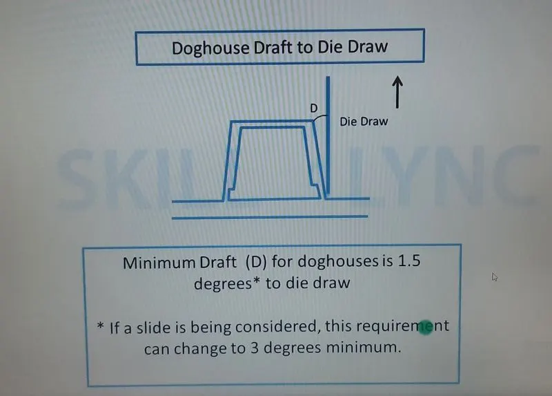
Dog house is feature which helps to avoid sink marks. If mating part is at far distance from B class surface, it helps to keep minimum length of screw boss. & if you want screw boss in opposite direction of tooling axis then it need dog house.
- Draft
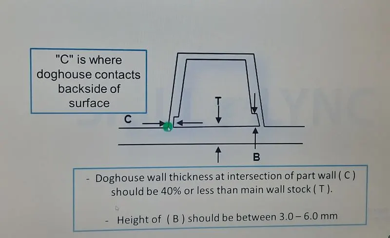
- Wall thickness:
- Height & width:
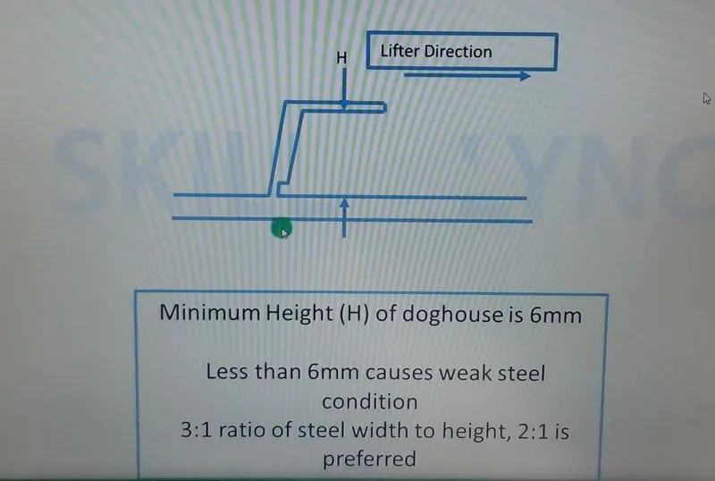
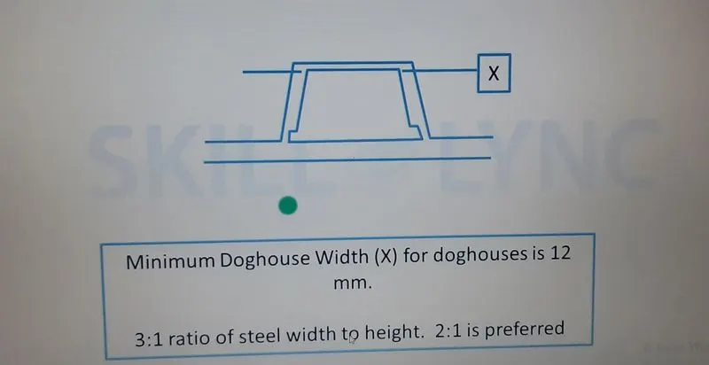
Design methodology:
To create dog house we need tooling axis, side core axis & position of screw boss.
To get position, Copy the existing screw boss body & paste it in main part. By using translate command position it to desired location.
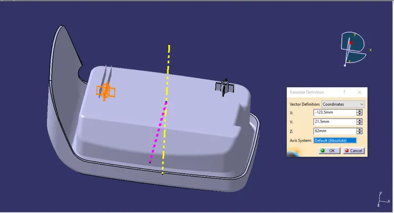
- Take a point at the centre of translated screw boss & isolate it. Create plane at that point & parallel to zx plane.
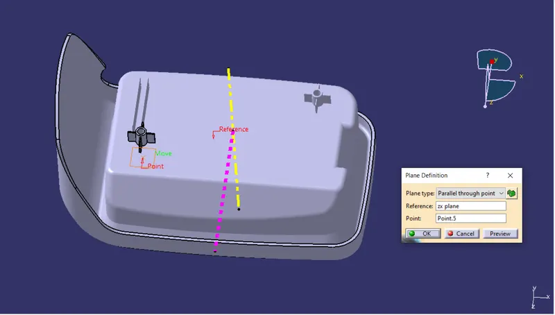
- Profile: Draw a rectangle sketch profile & make one side of rectangle as construction element.
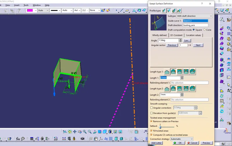
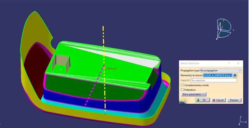
- Extract the class A surface bottom face & offset it by 2.5 mm.
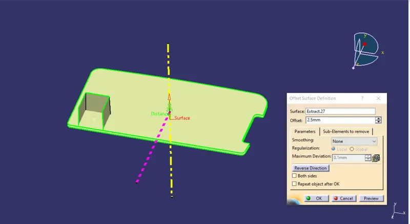
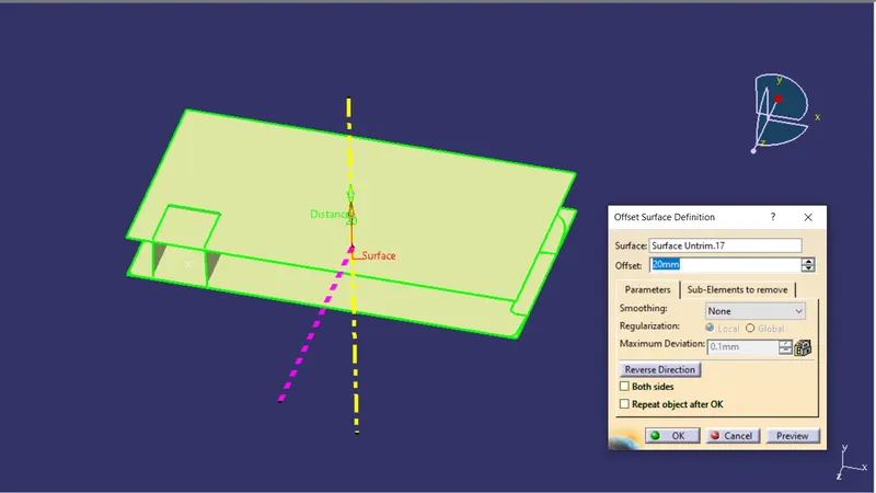
- Untrim the offsetted surface. & again offset it by 20 mm.
- Trim it with sweep surface & Add 1 mm fillet to edges.
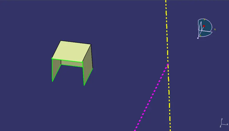
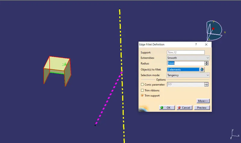
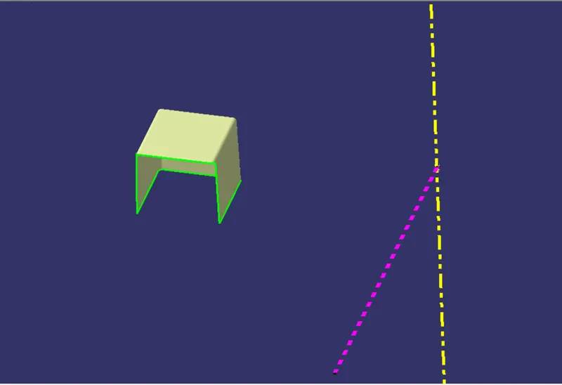
- Add 2 mm thickness to this surface.
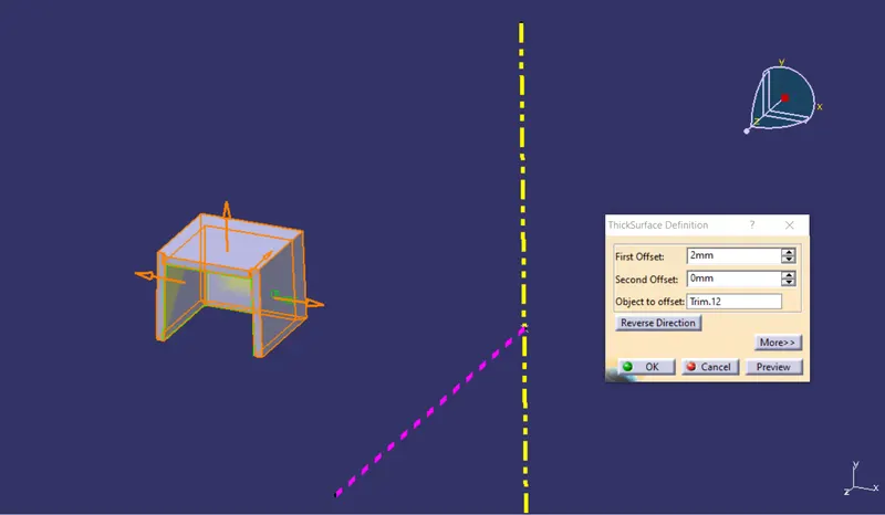
- By looking at model some faces need to be corrected which are projecting these will create problem during drafting the faces.
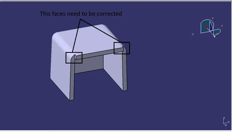
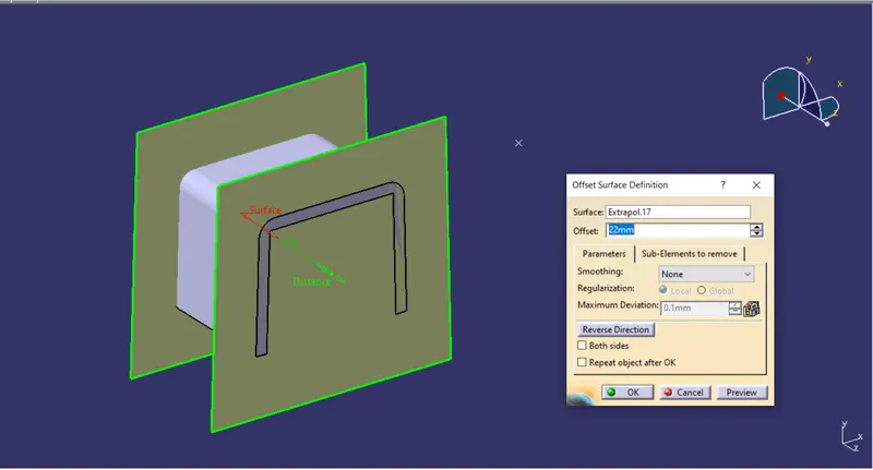
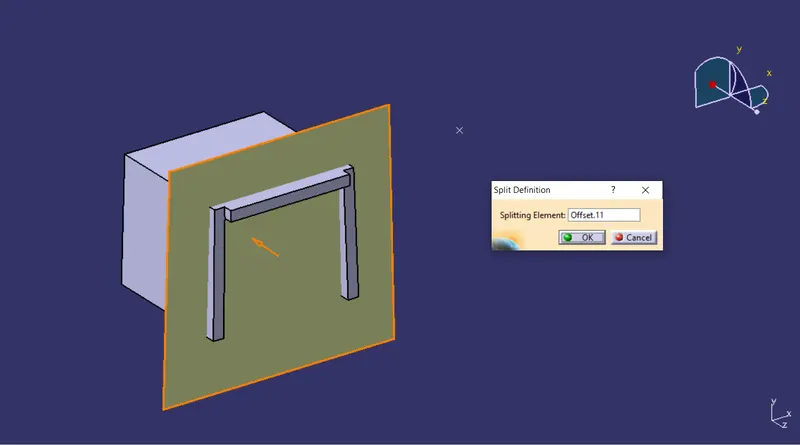
- To correct this, extract sweep surface then extrapolate it by 10 mm. then offset to a distance of 22mm. Split body with surface.
- Creating side core axis:
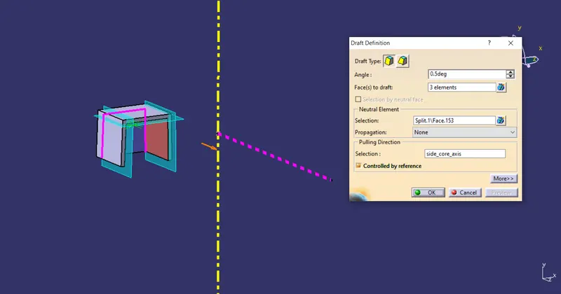
Now checking feasibility of dog house for manufacturing faces shown in below image are clearing in main tooling direction. Inside face are not cleared using main tooling axis & require draft to be given in the direction of side core axis.
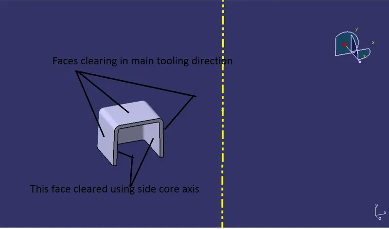
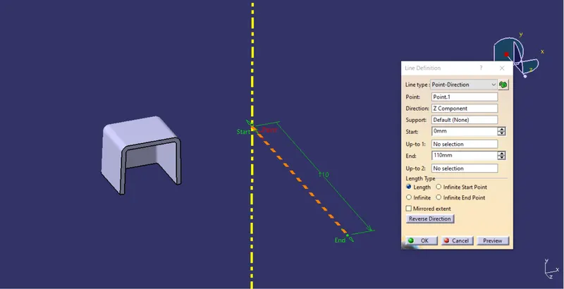
- Create a line by taking same reference point as main tooling axis & Z axis as direction. This is side core axis.
- Draft inside faces along the side core axis.
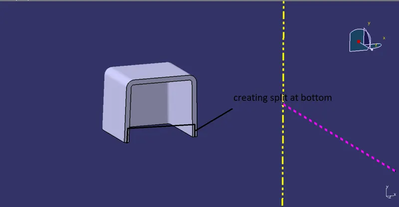
- Now we have to reduce thickness of dog house from base to at height between 3-6 mm to avoid sink marks.
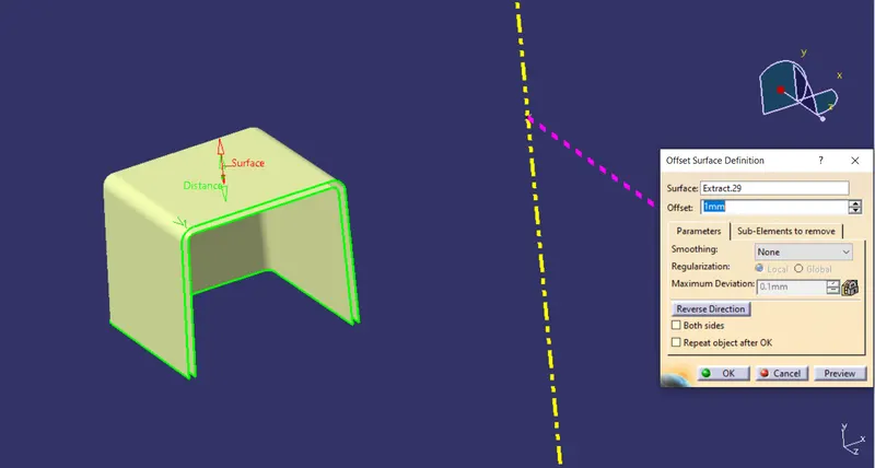
- So extract the inside faces of screw boss. Offset it by 1 mm as per calculation 0.4*t & then extrapolate.
- Similarly, extrapolate bottom surface & offset it to 4 mm as per design rule this is within limits. Trim these surfaces together.
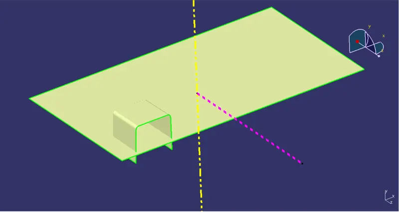
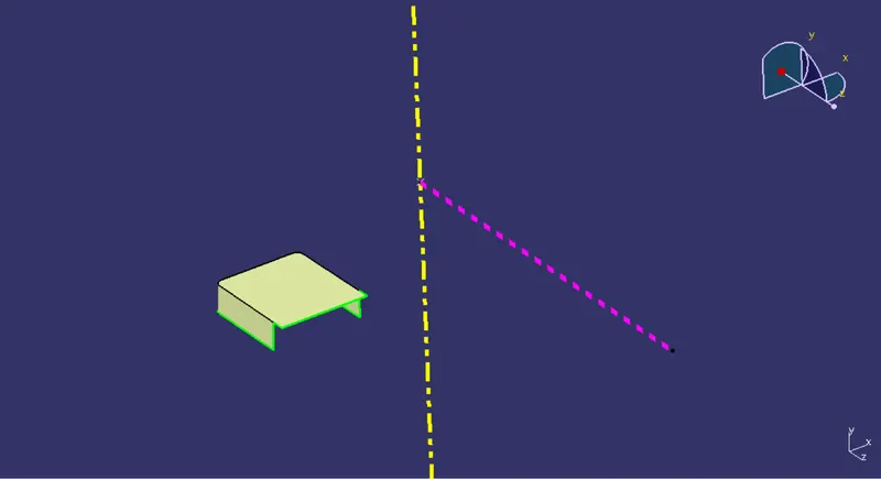
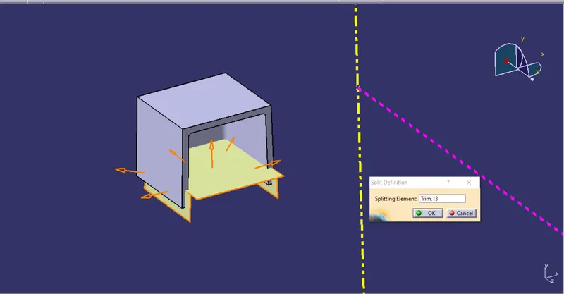
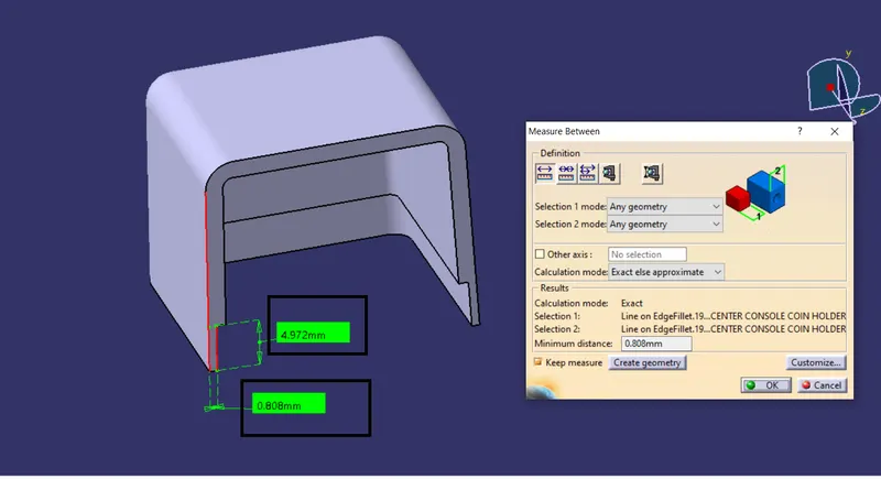
- Now as per design rule, Doghouse wall thickness at intersection of part wall C = 40% or less than main stock wall. By measurement in our part we get,
C =0.8 mm.
Height B = 5mm (which should be between 3 to 6 mm.)
- Now we have to also provide draft to bottom splitted faces. So, adding 0.5° draft to these faces.
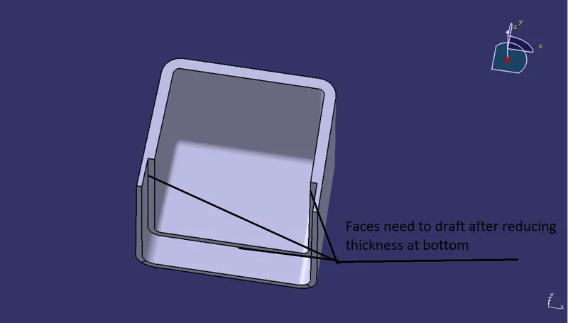
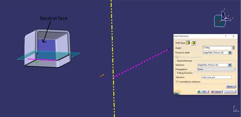
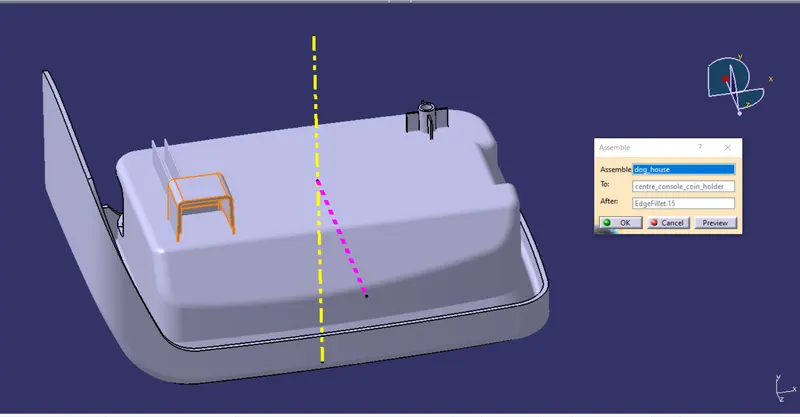
- Split dog house body with surface & fillet edges to 0.25 mm. Add dog house body to main coin holder body.
Performing draft analysis:
- To perform draft analysis. Go to insert < Analysis< Feature draft analysis.
- Switch customize view parameter mode to
- Click on compass icon & align it with the tooling axis & click on the surface, we will get our results. See color scale variant.
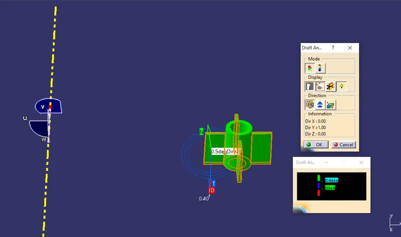
- Draft analysis of screw boss using main tooling axis.
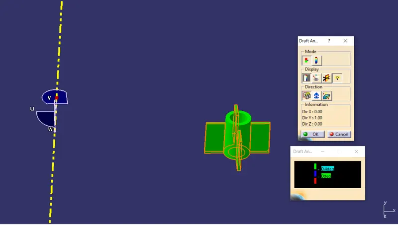
- Surfaces in green color have +ve draft value i.e. around 0.5° draft. So it clears main tooling direction.
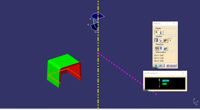
- Draft analysis of dog house using main tooling axis.
- Running point analysis.
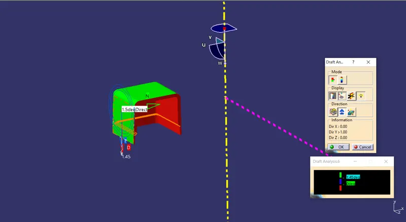
What is color scale variant?
- Surfaces in green color have +ve draft value.
- Surface in blue color have value between 0 to 1.5° draft value. See running point analysis.
- Surfaces in red color have –ve draft value.
The outer surfaces in green color have around 1.5°. These will be cleared by main tooling axis. The inside red color surfaces have negative draft & these will not be clear by main tooling axis. It will be cleared by side core axis. Performing draft analysis using side core axis for inside faces.
- Draft analysis of dog house using side core axis
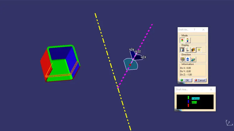
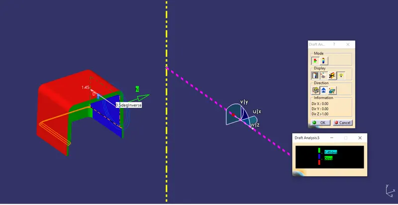
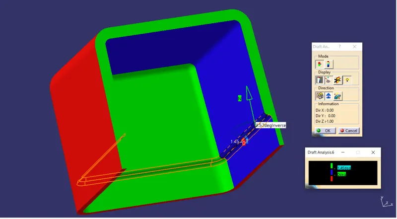
From above image it is seen that inside surface of dog house in blue color has 0.5° draft & will be cleared using side core axis.
Conclusion:
from the above images it is clear that dog house clears main tooling direction as well as side core axis.
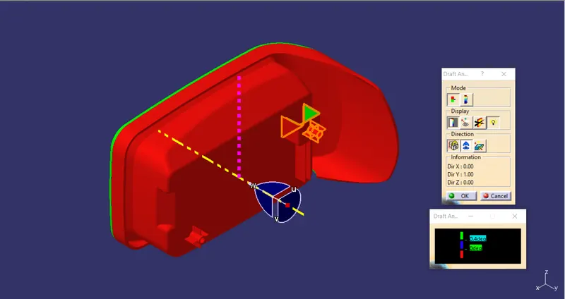
- Draft analysis on final part using main tooling axis:
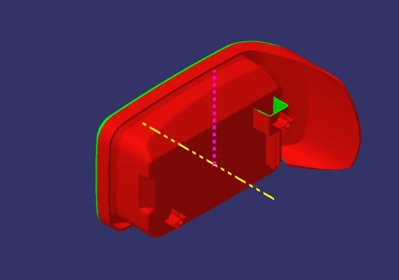
Various orientation of component:
- ISO view:
- Front view:
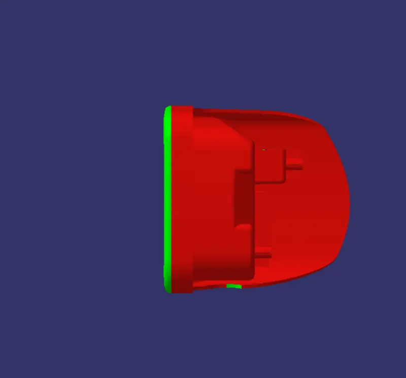
- Top view:
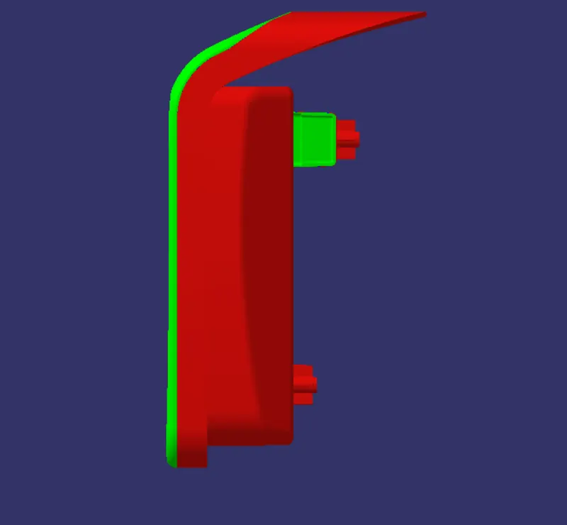
- Left side view:
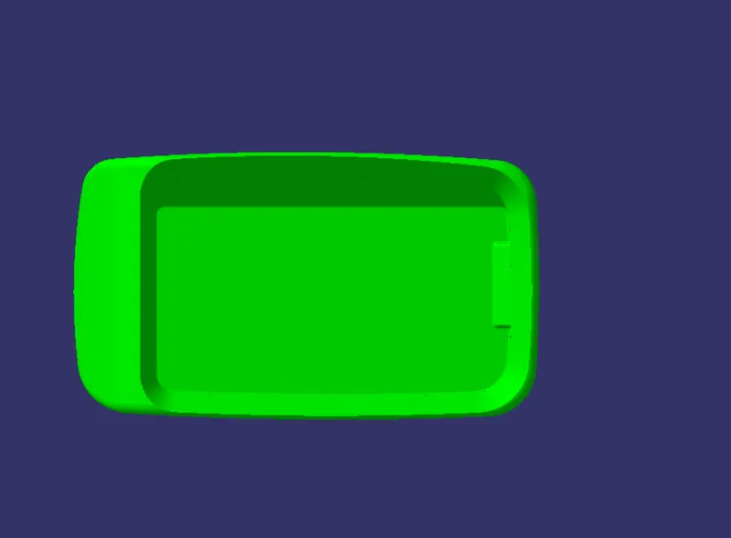
- Right side view:
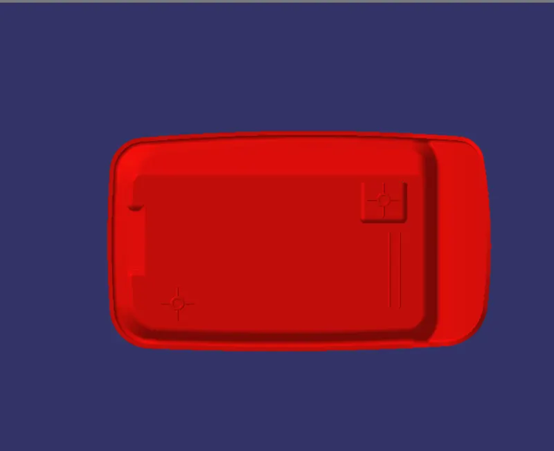
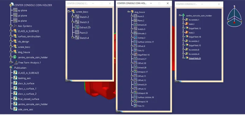
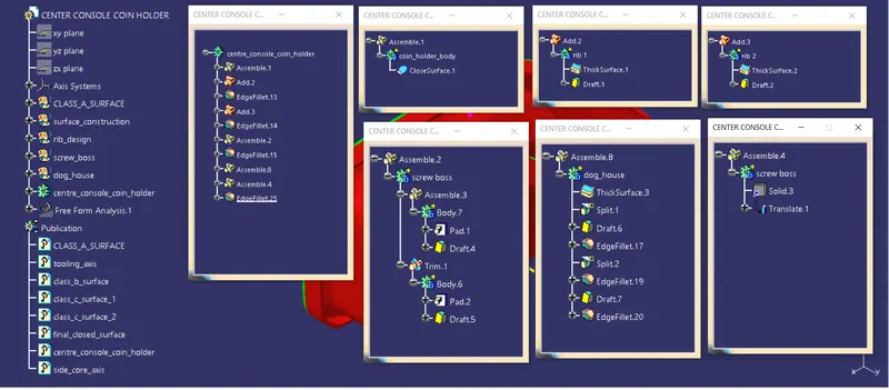
- Image of the expanded tree structure for the geometrical sets & part body.
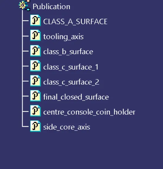
- Image of the publications of tooling axis & class A, B & C surface.