Week 9 - Attachment Feature Creation - Challenge 2
Why Draft Analysis ?
The primary purpose of Draft Analysis is to see if all faces of the Class A surface clear the Tooling Axis. This way, we can confirm if the Tooling Axis we assumed after the initial Visual check is correct for our Class A surface and if it's okay to go on ahead and design the part considering the assumed Tooling Axis as the actual Tooling Axis.
Brief Process of Tooling Creation -
- First we perform a Visual Check. This is done axis by axis. We consider each and every direction one after the other to see how it could work as a Tooling Axis. We then decide on an Axis which we feel has the lowest complexity in terms of Mold Design and Build costs.
- We then make a Dummy Tooling Axis along the chosen Direction (in this particular example - Z Direction).
- Then using Intersect command, we draw out the Boundary perimeter of the Class A surface that is travelling along the other two directions (X and Y). This is done one direction after the other.
- Once the perimeter is laid out, we perform a check to see which particular boundary lines may cause a problem in Tool clearing (More on this later).
- Once the potential problem lines are found out, we make a line clearing the tool in that particular direction. We repeat this method for both directions. This potentially gives us two tool clearing lines (highest possible number, can also be just one).
- Once these lines are created, we use the Bisecting Method to create the Actual Tooling Axis.
- Now, using this Tooling Axis, we perform a Draft Analysis (More on this later).
Bisecting Method -
This is the method to find out a line that is bisecting any two given lines. This method is used in Tooling creation to find out Tooling Axis and Lines clearing Tools in particular directions.
- Lines clearing Tools in Particular Directions -
As mentioned previously, we use the Intersect command to make a boundary perimeter line that intersects the Class A surface along the direction chosen. Then the boundary is studied thoroughly to see if there's any faces that might cause problems in tool clearing. Once these faces are found, we make tangential lines passing through these faces. After all these lines are extended, we use the Bisecting command from Line feature to create a line clearing the tooling in that particular direction (X or Y in this example).
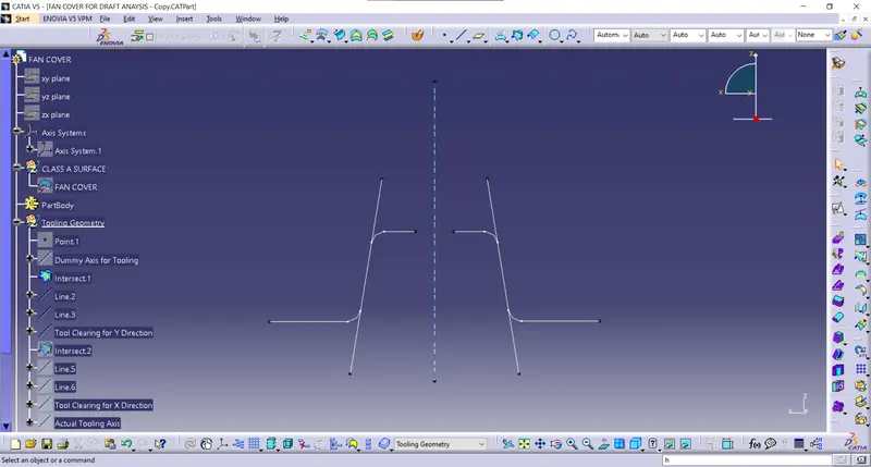
As can be seen in the picture above, the slant faces might be a problem in tool clearing. So, we make lines tangent to them and then bisect them and make a new line that clears the tool.
- Tooling Axis -
This is the main axis that we create. The method followed here is the same as the one we used to make the line in the previous case. The only difference in this method is that the reference lines we use are the lines we created in the previous step/method. The lines clearing x and y directions respectively are used as reference lines which are bisected to get the final tooling axis.
As we can see in the command window we use the two lines clear X and Y directions respectively to make the bisect for the Final Tooling Axis.
Draft Analysis -
In Draft Analysis we find out if the Tooling Axis created in the previous steps is toolable. We find out if all the faces of the surface fall within the Draft limit.
It is done in the following way -
- We first start off by initiating the Draft Analysis command window (Insert -> Analysis -> Feature Draft Analysis).
- Then we come across a Command window as shown below .
As we can see, we have two mini-windows. One for setting the Draft Angle paramaters (also called as Colour Scale Variant). The other to setup the Tooling Axis direction and it also has other features.
3. We then set the Tooling Axis of the Surface using one of the options available in the command window. We use the tooling surface we created as the reference axis.
4. We then lock the axis and set the Draft angle parameters.There are three different colour variants.
GREEN - This is shown when all the faces in the Class surface have angles (with respect to the tooling axis) greater than that of the Minimum Draft Angle mentioned. 3 Degrees is the industry norm. > 3 Degrees
RED - The faces that have angles between 0 & 3 Degrees is shown in red. This means that the tool design axis is a no-go.
BLUE - This is used when the angle is < 0 Degrees. When this happens, we can just invert the direction of tooling to make it right.
TREE STRUCTURE -
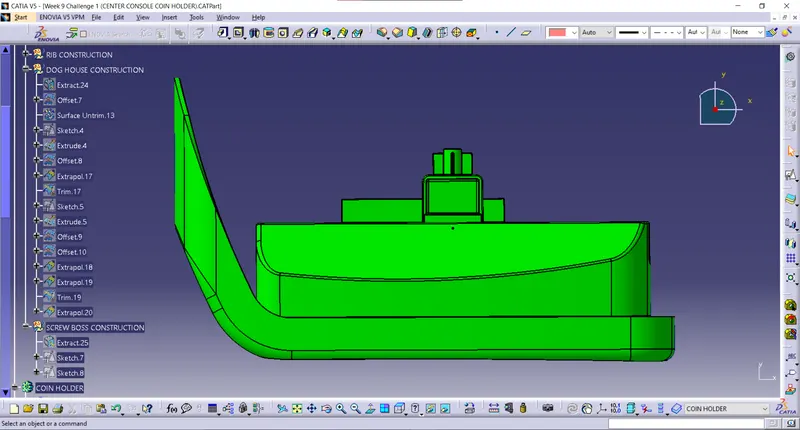
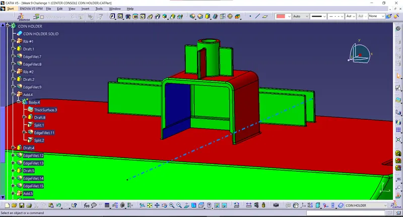
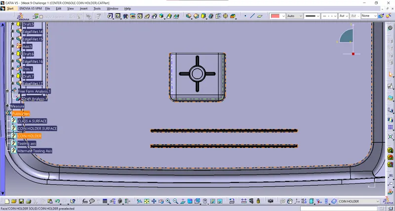
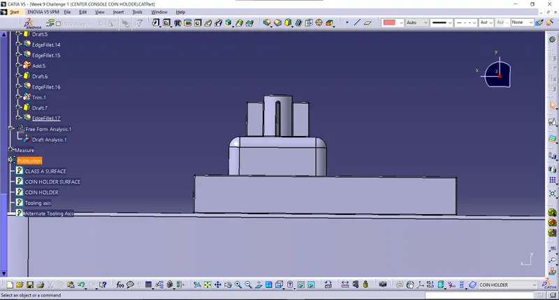
DRAFT ANALYSIS RESULTS - (IN DIFFERENT VIEWS)
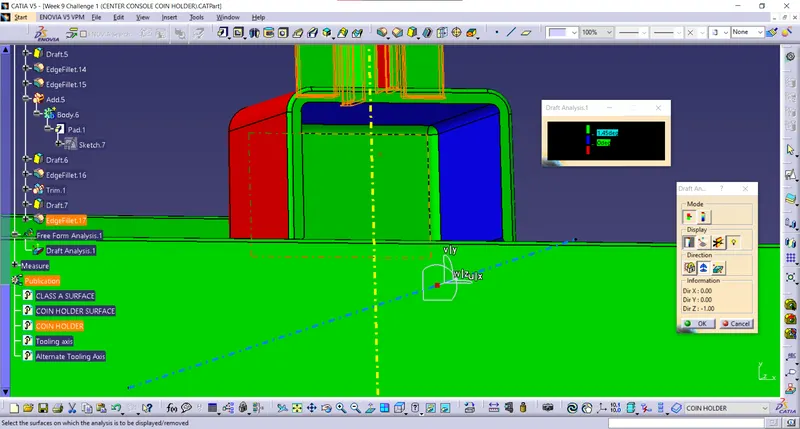
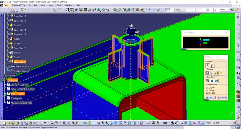
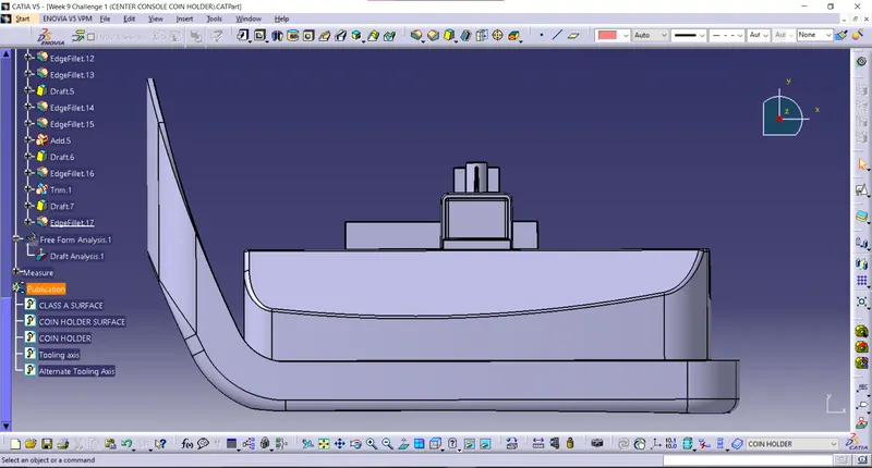
DIFFERENT VIEWS OF THE PART BODY -