Week 8 - Challenge 2 - Base Bracket Design
Draft Analysis -
The process of checking every face of the Surface to see if it clears the tooling according to the direction given as the Tooling Axis. For this we first need to decide a Tooling Direction and using that make a Tooling Axis. The process of making the tooling axis is as follows -
- Perform a visual check on the Class A surface that is given. From this we can get a vague idea as to which direction would be the most efficient direction for Tooling to be performed along. Upon settling on this direction, we make a dummy tooling axis along this direction.
- Once the dummy axis is made, we now check the surface flow along the other two directions to find if there are any problematic faces along these directions that may cause a problem in Tool clearing. This is done through the following method-
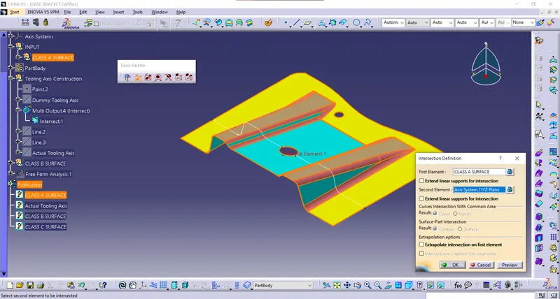
1. We use the Intersect command to make a boundary perimeter of the surface that intersects the axis we chose as reference.
2. We use the line command and extend the lines that may be problematic along the chosen tooling axis direction. We then use Bisecting line command from the line feature and then using the two lines we made as references, we make a bisecting line. This line indicates the line that is to be followed to clear the tool in that particular direction.
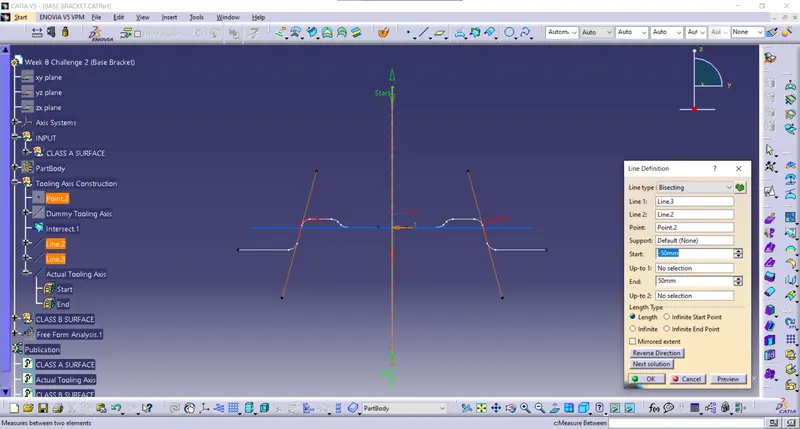
As can be seen from the picture above, the bisecting line command is used to make a line using the two slant lines as references. This method can repeated in both directions if there's any doubtful faces. In this case, we just do the one direction because, we know for a fact that the other direction will clear the tool.
3. We usually then perform this method for the other direction and then we perform the Bisecting method again to create the tooling axis. In this method, since we have doubtful faces in only one direction we directly use the line made there as the Actual Tooling axis.
4. We then perform Draft Analysis on the surface taking the Tooling Axis we created as reference. This is performed as follows -
- Go to Insert --> Analysis --> Feature Draft Analysis.
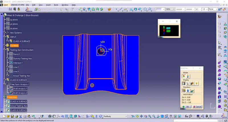
- Upon clicking on this we get two mini-windows as shown below. One is to show the angles of the faces with reference to the Tooling Axis. Other one is the command window which helps us set the draft parameters and many other functions.
- First we need to set the tooling axis we created as the tooling axis for the Surface. There is a command available for this in the mini-window.
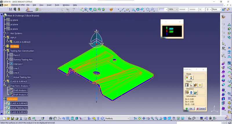
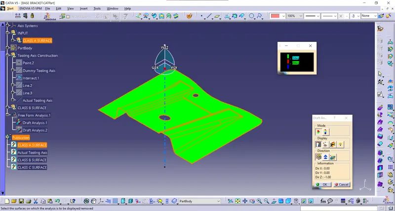
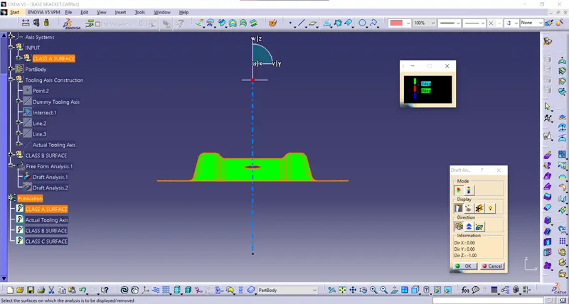
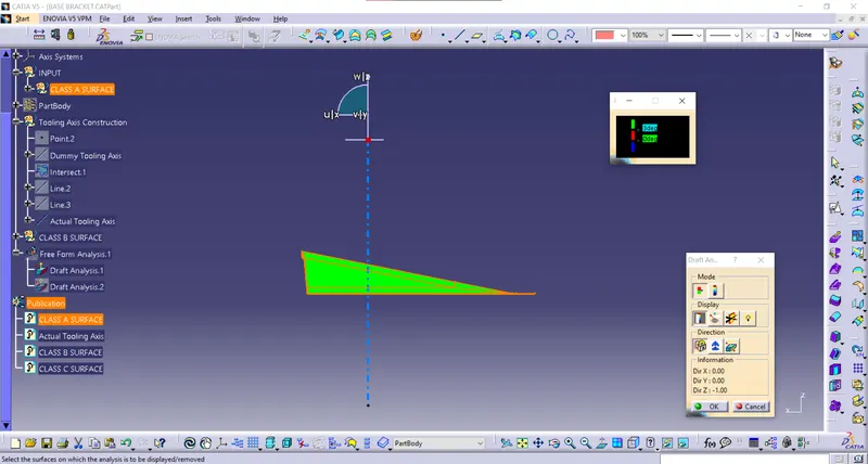
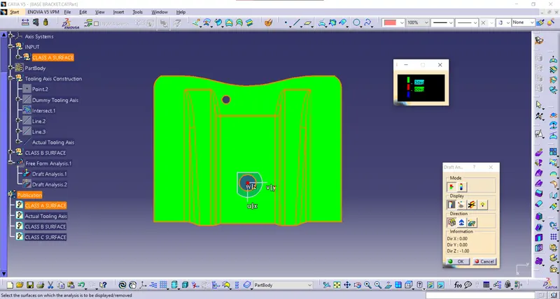
- Once this is done, we set our angle parameters in the other window (in terms of angles). This window is also called Colour Scale Variant. This Variant has three colours as can be seen below. Green is shown when the faces make an angle greater than the minimum Draft Angle set (Usually 3 Degrees). Red is shown when the angle lies between 0 and 3 Degrees. This is problematic. Blue is shown when the angle is less than 0 Degrees (< 0 Degrees).
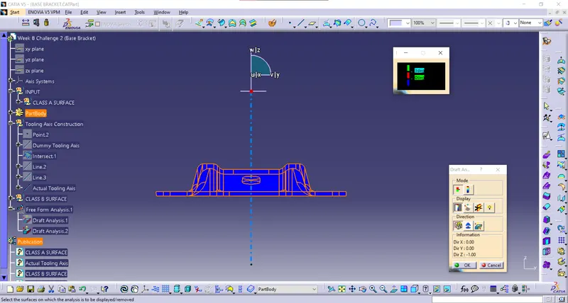
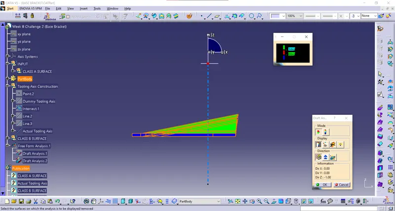
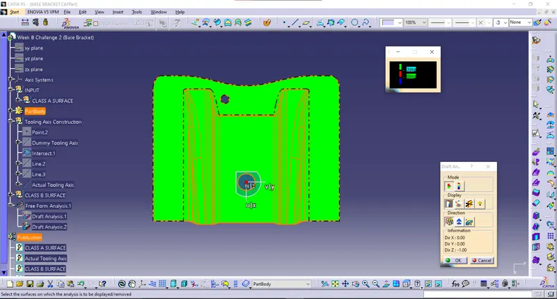
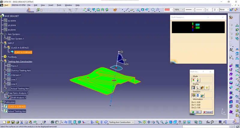
- Once these angles are set, we can Lock the tooling axis. Upon doing this we get a red cross marker. Now, we have to choose the surface on which Draft analysis is to be performed. It then gives us the results of the Draft Analysis in the form of the colours we talked about before.
TREE STRUCTURE -
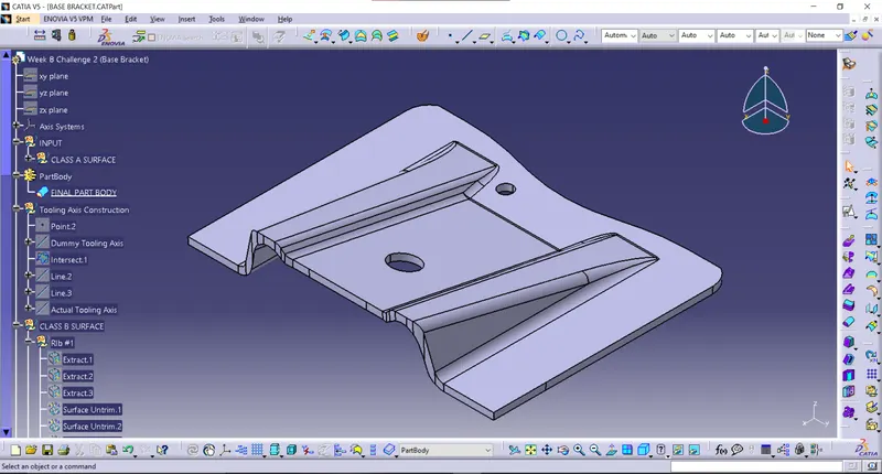
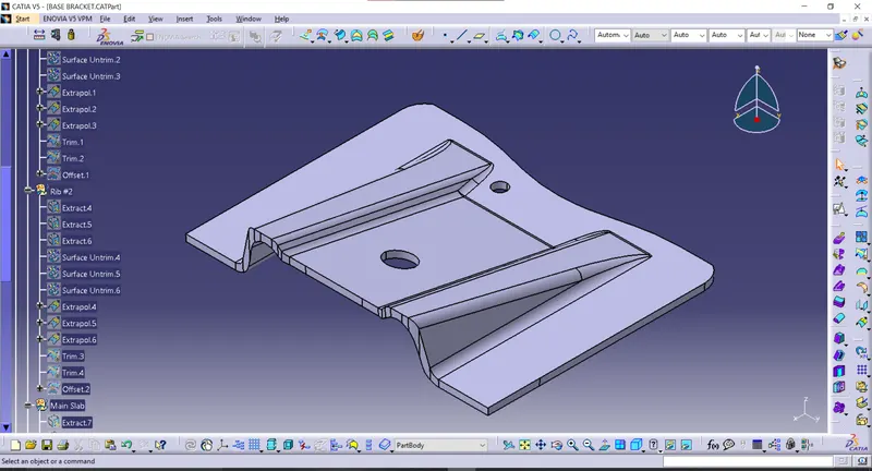
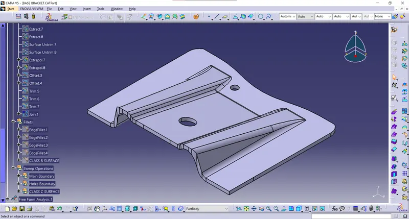
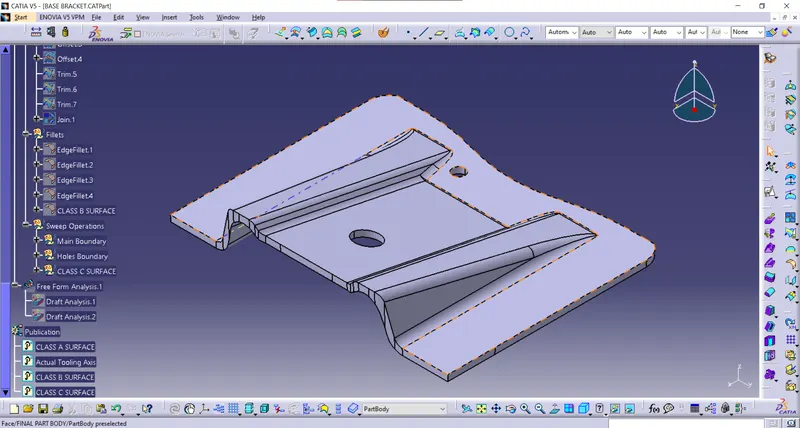
DRAFT ANALYSIS OF CLASS A SURFACE -
DRAFT ANALYSIS OF THE FINAL PART BODY -