Week 9 - Attachment Feature Creation - Challenge 2
AIM
- To Create the Door Trim Plastic component through the given Class-A surface
- To create the tooling axis for the given Class-A Surface meeting the requirements of the draft angle and at the end perform the Draft analysis on the model.
- Create the Dog House for the Door Trim considering the design rules.
INTRODUCTION
Door Trim is an interior component which is attached to the inner side of the door. This product does more than merely improve the appearance of the vehicle interior. Rather, it is a vital module component that creates a more comfortable interior by providing a variety of accouterments and functions.
It also covers the parts inside a car door, like the window regulator, power window motor, and wirings. It also protects these components from damage.
Material Used & Why?
Plastic is the preferred material for car interior trims for several reasons. First and foremost, plastic is much lighter than metal, which improves the car's fuel efficiency. Plastic is also easier to shape, which is useful during the manufacturing process.
The material used for this Door Trim is ABS (Acrylonitrile Butadiene Styrene) plastic. It is because this part is attached to the inner side of the door, so that it should provide good surface finish as well as impact-resistant. Plastic used in cars, like ABS, helps the body absorb and redistribute energy during an impact.
DESIGN METHODOLOGY
Class-A Surface
Class-A surfaces refer to those surfaces which are visible in a product. In other words, class-A surfaces are those aesthetic/free-form surfaces, which are visible to us (interior/exterior), and have an optimal aesthetic shape and high surface quality. It is created by the styling team and gives to the part design engineer to create the part with all engineering aspects.
Class-A Surface:
The given class-A surface is checked whether there is any patches or not using bondary command.
Tooling Axis Creation
The tooling axis is the direction of drawing a sheet metal where the finished component is easily ejected on a particular direction and axis.
In Molding, machine arrangement is given to open the mould along a direction which is known as Tooling Direction. In other words. The mould is built from two separate halves (Core and Cavity) and tooling direction basically defines the direction of mould pulls apart.
There are 3 methods to create tooling axis, which are :
- With respect to 3 axis (X, Y, & Z)
- Normal to surface
- Bisecting method
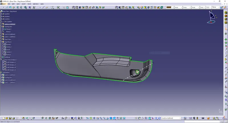
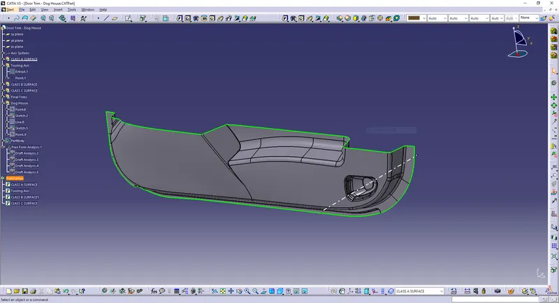
In the given model tooling axis is found out using Normal to Surface method.
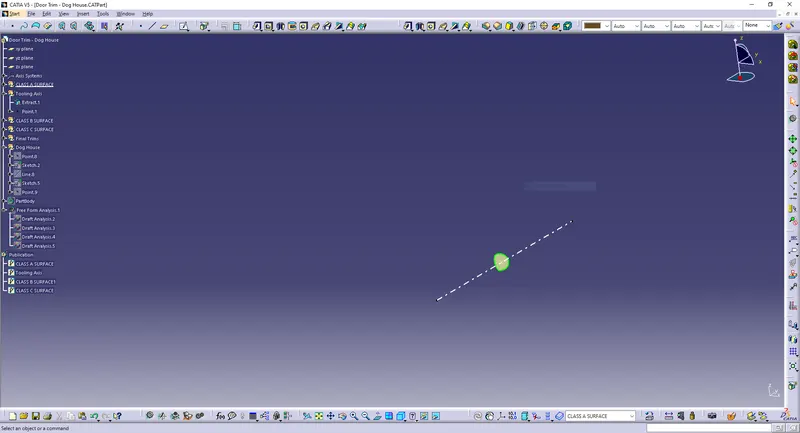
In the given model (Door Trim), it will clear all the surfaces in its Y-axis direction, so that the surface approximately perpendicular to Y-axis is chosen and is extracted from the class A surface. Tooling axis is created normal to that extracted surface.
Extracted surface is given below:
Tooling Axis:
Draft Analysis - Class-A Surface
In the criteria of making a plastic material, the mold should release the material when finished. If the mold surfaces are 90 degrees the material won't release from the mold because of friction due to contraction of material when cooled.The ejection of the part from mold depends on the draft. A zero draft can result in difficult or no ejection. It is recommended to add a draft of 3 degree or above inorder to remove it from the mold without any damage.
Procedure:
- Change the view mode of the component to be in customized parameter mode and then select the shading mode as materials.
- In the draft analysis toolbar, set the draft values and color (3 degree and above as green, 0 to 3 degree as blue, less than 0 as red).
- Drag and drop the axis system on the tooling axis and lock it.
- Perform draft analysis.
Draft analysis of Class A surface:
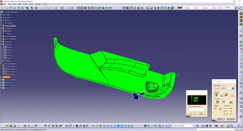
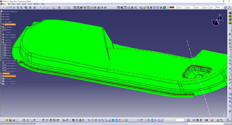
The above result of draft analysis shows red colour in some areas. It is because the surface angle is in negative direction. Therefore, the part is difficult to manufacture. The above part can be modified by class A engineer in order to clear the required portions to manufacture the part without any defect.
Creation of Class B & C Surfaces:
Class-B Surface
It is the offset of the class-A surface at a particular distance. The offset distance depends on the thickness between Class A and Class B surface.
Here, the thickness given = 2.5mm.
Procedures to build class B surface:
- Offset the joined class-A surface to 2.5mm inward direction.
- Rework on the patches and discontinuity of the offset surfaces using the features like extract, multi-extract, sweep, multi-section surfaces, extrapolate.
- To ensure the continuity of the Class-B surfaces check the boundary command to find out the boundary.
- Hence class-B surface creation is done.
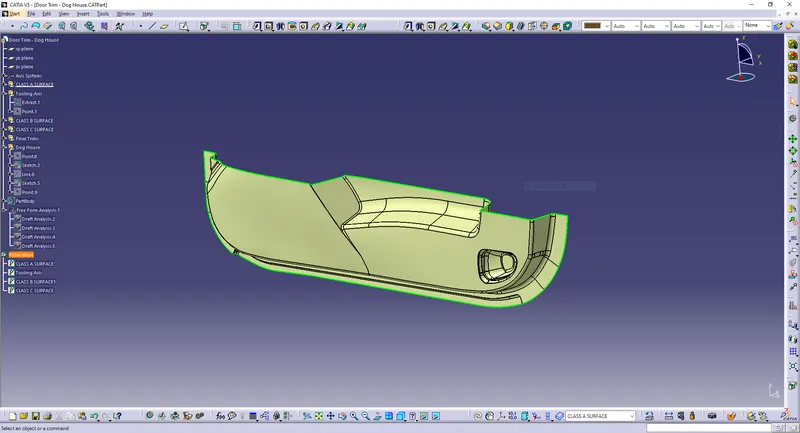
Class B surface offseted 2.5mm is given below:
Class-C Surface
This surface connects the Class A and Class B surfaces. (Surface in between Class A & B surfaces)
Procedure to build Class C surface:
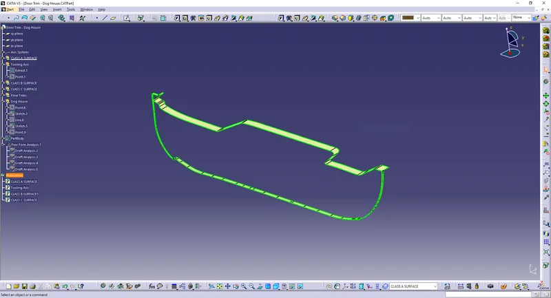
Since it is a complex class-A surface, we cannot simply create the class-A boundary curve and sweep it at one shot. Hence, we need to create smaller boundaries using boundary command and then create sweep of 90 degrees with reference to the surface option if the class C should come in perpendicular to tooling axis. Sweeps at the areas were class C should come parallel to tooling axis should have a 3 degree draft vaue with repect to tooling axis to pass the draft analysis. Also, at the fillet/curve areas, use multi section surface inorder to sweep and complete the class C surface.
Join every induvidual sweeps using join command and for the edges which hasn't joined, extrapolate and trim off the sweep surface corners at the required edges.
The Class-C Surface:
Final Surface Creation
Joining and Closing of Class A,B & C surface:
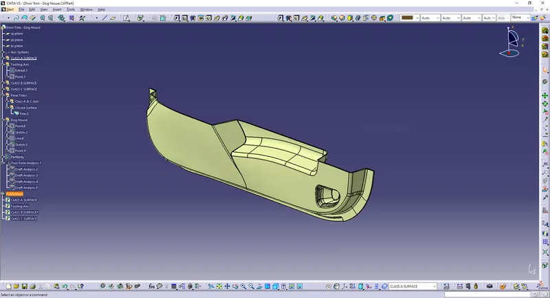
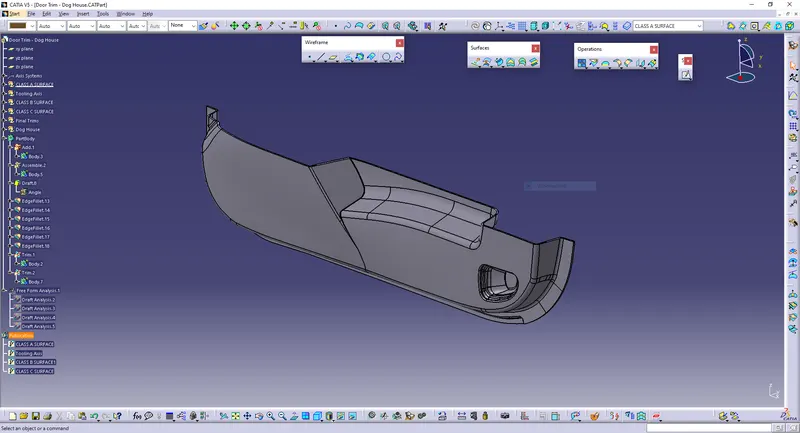
After creating class B & C surfaces joining operation is done between class A and class C surface. Then, Class B surface is trimmed with joined Class A & C surface to get a whole closed single surface. Then in part workbench using closed body command, a solid body is generated.
Closed surface:
Solid Body:
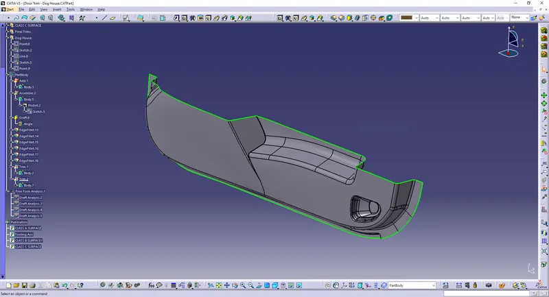
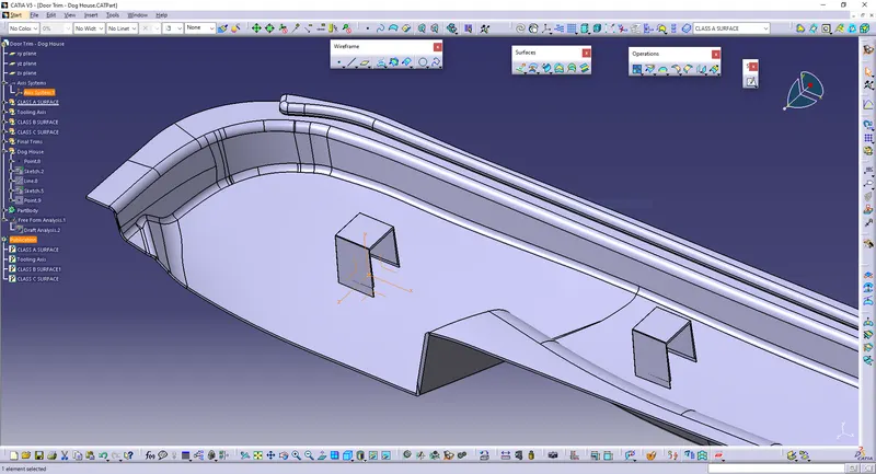
Dog House Creation
Dog house is an engineering feature used in plastic trim design. Dog houses are used as supporting feature. Sometimes other engineering features like snaps, locators etc. are mounded on them to increase their strength. Dog houses are subjected to draft analysis to prevent breakage of the component during ejection from mould cavity. Dog house and other engineering components are built on B-surface.
Procedure for Dog House:
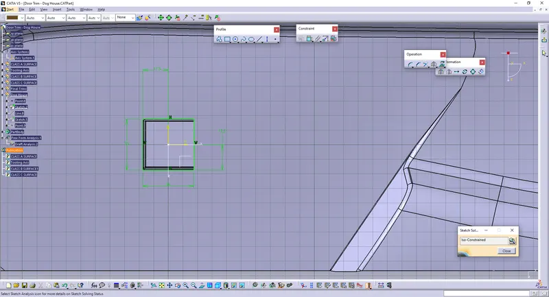
- C thickness should be 40% of the main wall thickness T
- Minimum width of the dog house is 12 mm.
- Height of B should be 3-6 mm
- Minimum draft for the do house is 1.5 degree to die draw.
Dog House sketch:
1. Inserting an axis system:
2. Dog House sketches:
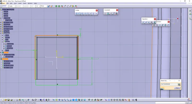
3. Dog House Tooling axis:
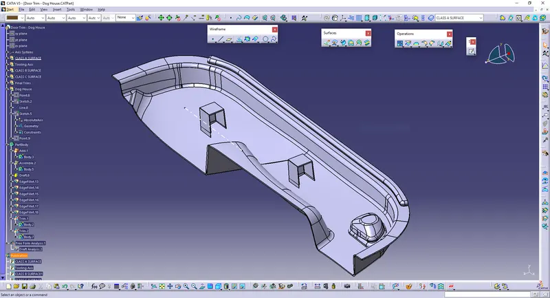
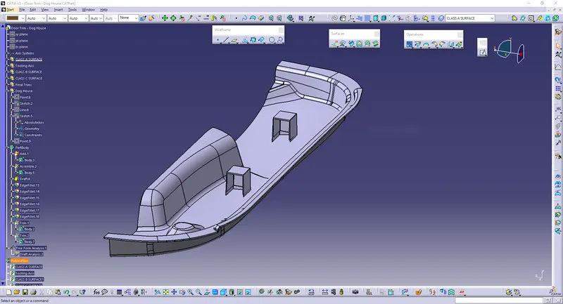
Final Solid body of Dog House:
Draft Analysis - Final Solid Body
Same procedure for the draft analysis of CLASS-A surface is followed.
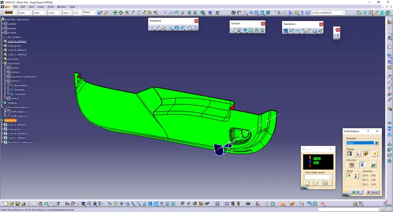
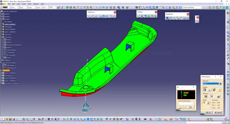
Hence draft analysis is done and the part is manufacturable.
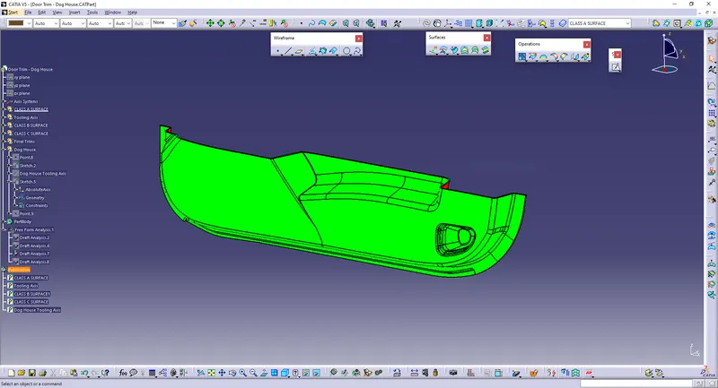
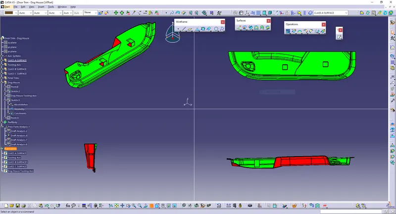
Screenshots of the solid model with the proper color code of the draft angle in various orientations:
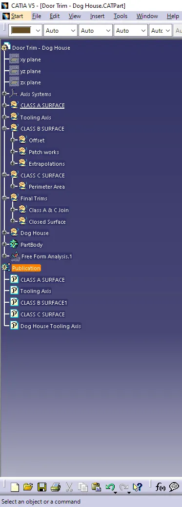
Tree:
CONCLUSION
Tooling axis is created properly for the given class A surface and based on that class B & C surfaces are made.Dog houses are created on the class B surface. Draft analysis is done for the class A surface and final plastic component and the results were obtained.