Week 8 - Challenge 2 - Switch Bezel Design
SWITCH BEZEL DESIGN REPORT
Aim : To Create the Switch Bezel Plastic component through the given Class-A surface
To create the tooling axis for the given Class-A Surface meeting the requirements of the draft angle and at the end perform the Draft analysis on the model.
Tooling Axis
The tooling axis is the direction of drawing a sheet metal where the finished component is easily ejected on a particular direction and axis.
In Molding, machine arrangement is given to open the mould along a direction which is known as Tooling Direction. In other words. The mould is built from two separate halves (Core and Cavity) and tooling direction basically defines the direction of mould pulls apart.
There are 3 methods to create tooling axis, which are :
- With respect to 3 axis (X, Y, & Z)
- Normal to surface
- Bisecting method
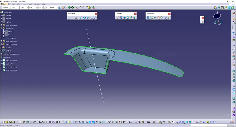
In the given model tooling axis is found out using Normal to Surface method.
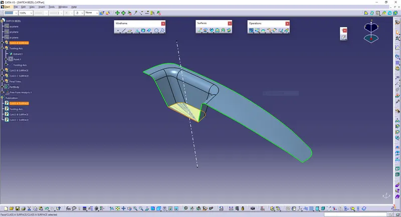
In the given model (switch bezel), it will clear all the surfaces in its Z-axis direction, so that the surface approximately perpendicular to z-axis is chosen and is extracted from the class A surface. Tooling axis is drawn normal to that extracted surface.
Extracted surface is given below (highlighed with orange colour border):
Tooling Axis:
Material Used & Why?
The material used for this switch bezel is ABS (Acrylonitrile Butadiene Styrene). It is because this part lies on the doorpad of the vehicle which should offer a sleek finish. Steering wheel covers and dashboards are often made of ABS plastic. Plastic used in cars, like ABS, helps the body absorb and redistribute energy during an impact, keeping passengers safe.
Class A,B & C Surface
Class A Surface:
It is the outermost aesthetic surface which is visible to customers (the outermost visible surface of a product).
Here, class A surface is given:
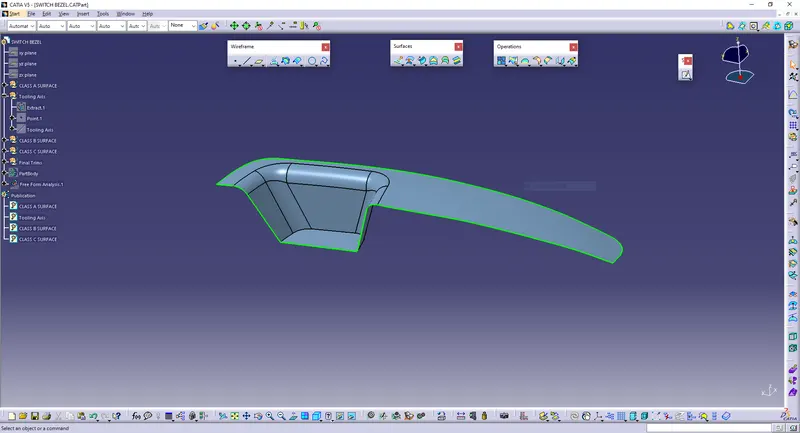
The class A surface is joined inorder to make it a single part and then checked the boundary to confirm that it is closed.
Class B Surface:
It is the offset of the class A surface at a particular distance. The offset distance depends on the thickness between Class A and Class B surface.
Here, the thickness given = 2.5mm.
Procedures to build class B surface:
- Extracted each and every flat surfaces from class A excluding fillets.
- Untrimmed all the extracted surfaces and offseted those surfaces 2.5mm downwards.
- Extrapolated the offseted surfaces inorder to make sure all the surfaces are in contact.
- Trimmed the offsets to get an output same as class A surface
- Fillets are given to the required edges based on the thickness and curvature of the class A fillets.
- For external fillets 17.5mm (15mm+2.5mm) is given and for internal fillets 11.5mm (14mm-2.5mm) is given.
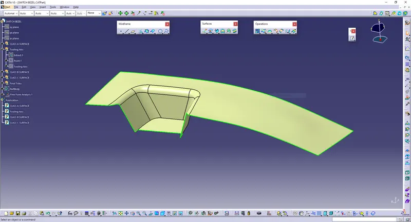
Class B surface offseted 2.5mm downwards (-ve Z-direction) is given below:
Class C Surface:
This surface connects the Class A and Class B surfaces. (Surface in between Class A & B surfaces)
Procedure to build Class C surface:
- Boundary of class A surface is extracted and then smoothcurved the boundaries
- Then that boundary is swept along the tooling direction until it gets coincided with the offseted class B surface.
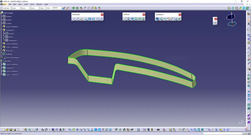
Joined and Closed Class A,B & C surface:
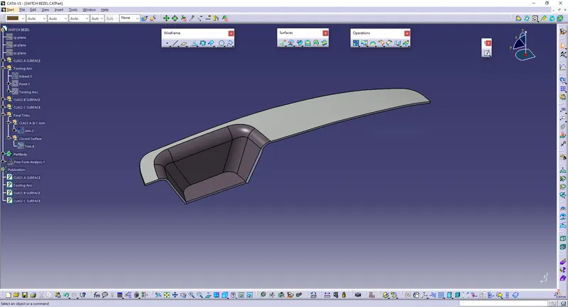
After creating class B & C surfaces joining operation is done between class A and class C surface. Then, Class B surface is trimmed with joined Class A & C surface to get a whole closed single surface. Then in part workbench using closed body command, a solid body is generated.
Figure is attached below:
Closed surface:
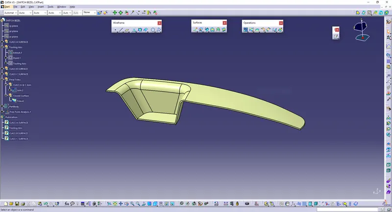
Solid body:
Draft Analysis
In the criteria of making a plastic material, the mold should release the material when finished. If the mold surfaces are 90 degrees the material won't release from the mold because of friction due to contraction of material when cooled.The ejection of the part from mold depends on the draft. A zero draft can result in difficult or no ejection. It is recommended to add a draft of 3 degree or above inorder to remove it from the mold without any damage.
Procedure:
- Change the view mode to customize view parameters and give material as view mode.
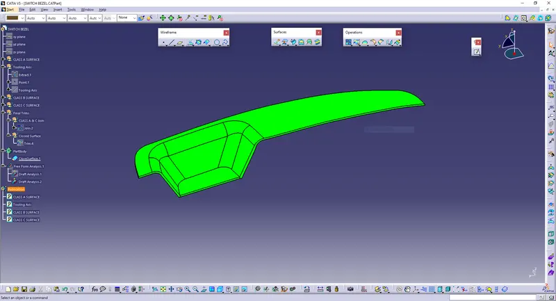
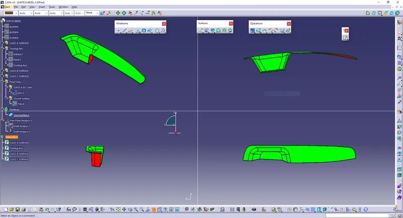
- In the draft analysis toolbar, set the draft values and color (3 degree and above - green, 0 to 3 degree - blue, less than 0 - red).
- Drag and drop the axis system on the tooling axis and lock it.
- Perform draft analysis.
Draft analysis of Class A surface:
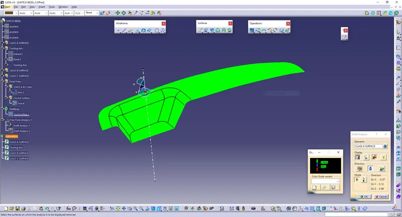
Drfat analysis of final plastic component:
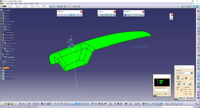
Hence draft analysis is done and from that it is understood that the part is completely manufacturable.
Screenshots of the solid model with the proper color code of the draft angle in various orientations:
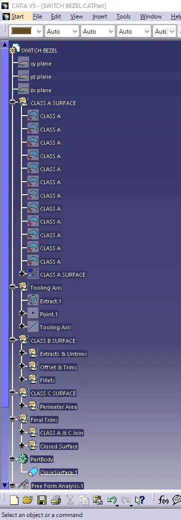
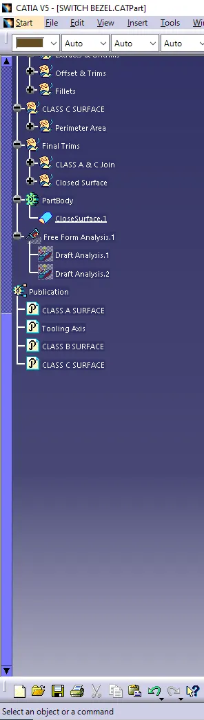
Tree:
Conclusion
Tooling axis is created properly for the given class A surface and based on that class B & C surfaces are made. Draft analysis is done for the class A surface and final plastic component and the results were obtained.