Week 8 - Challenge 4 - Bumper
BUMPER DESIGN REPORT
AIM
- To Create the Bumper Plastic component through the given Class-A surface
- To create the tooling axis for the given Class-A Surface meeting the requirements of the draft angle and at the end perform the Draft analysis on the model.
INTRODUCTION
A bumper is a part attached to the front and rear ends of a motor vehicle. They are designed to absorb impact to the front and rear of vehicles and minimize low-speed collision damage, ideally minimizing repair costs.
Modern car bumpers are made from thermoplastic olefins, a blend of plastic molecules, rubber, and a reinforcing filler like carbon fiber or calcium carbonate. This blend of materials creates a scratch and impact-resistant plastic that can bond with a wide range of paints and finishes, making it ideal for vehicle bumpers.
Material Used & Why?
Plastic is the preferred material for modern car bumpers for several reasons. First and foremost, plastic is much lighter and more aerodynamic than metal, which improves the car's fuel efficiency. Plastic is also easier to shape, which is useful during both the manufacturing and bumper repair process.
The material used for this Bumper is ABS (Acrylonitrile Butadiene Styrene). It is because this part is attached to the front and rear ends of a motor vehicle which should absorb the impact at both the front and rear ends, also it should provide good surface finish as well as impact-resistant. Plastic used in cars, like ABS, helps the body absorb and redistribute energy during an impact.
DESIGN METHODOLOGY
Class-A Surface
Class-A surface would be provided to us by the styling team to us. Class-A surface means visible surface. It gives the aesthetic of the component which is created by the styling team and gives to the part design engineer to create the part with all engineering aspects.
Class-A Surface:
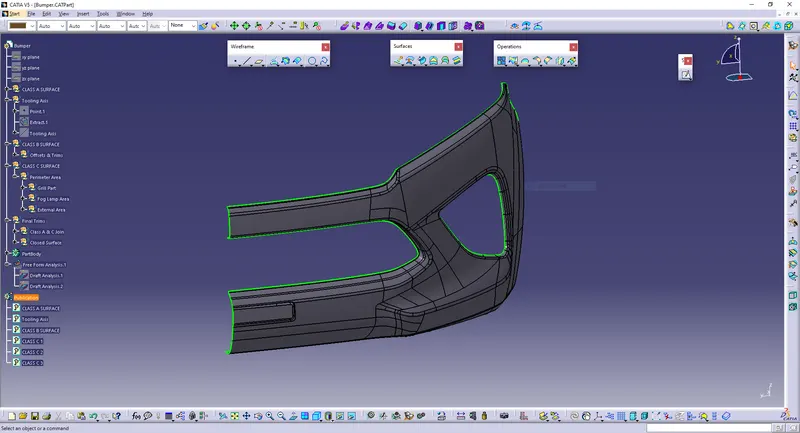
The class A surface is joined inorder to make it a single part and then checked the boundary to confirm that it is closed.
Tooling Axis Creation
The tooling axis is the direction of drawing a sheet metal where the finished component is easily ejected on a particular direction and axis.
In Molding, machine arrangement is given to open the mould along a direction which is known as Tooling Direction. In other words. The mould is built from two separate halves (Core and Cavity) and tooling direction basically defines the direction of mould pulls apart.
There are 3 methods to create tooling axis, which are :
- With respect to 3 axis (X, Y, & Z)
- Normal to surface
- Bisecting method
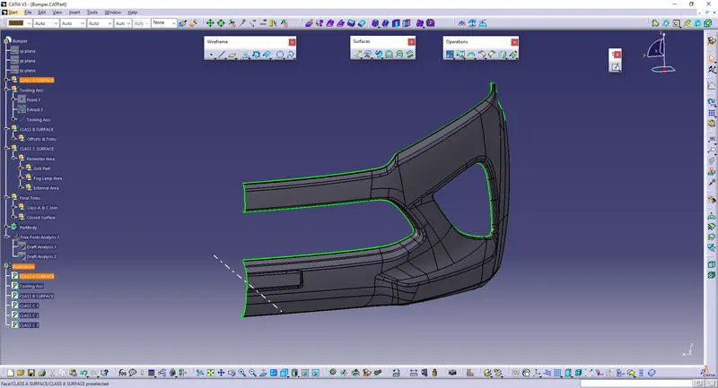
In the given model tooling axis is found out using Normal to Surface method.
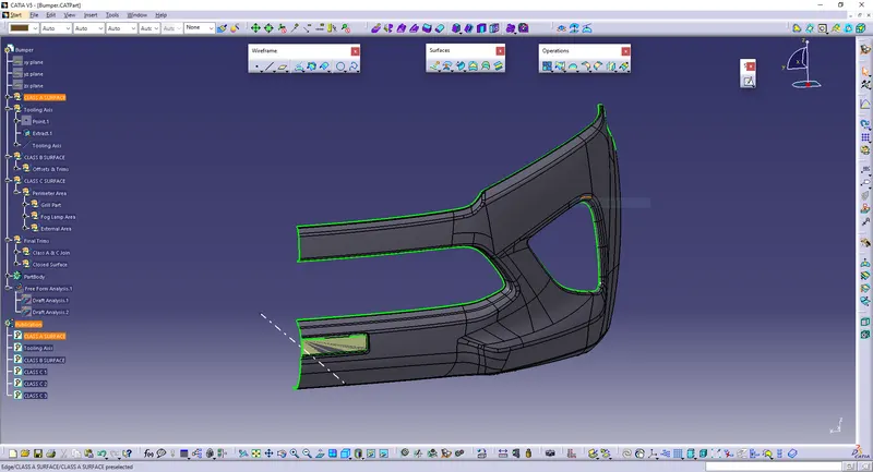
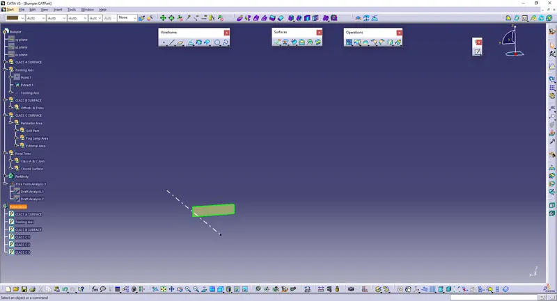
In the given model (Bumper), it will clear all the surfaces in its X-axis direction, so that the surface perpendicular to X-axis is chosen and is extracted from the class A surface. Tooling axis is created normal to that extracted surface.
Extracted surface is given below:
Tooling Axis:
Draft Analysis - Class-A Surface
In the criteria of making a plastic material, the mold should release the material when finished. If the mold surfaces are 90 degrees the material won't release from the mold because of friction due to contraction of material when cooled.The ejection of the part from mold depends on the draft. A zero draft can result in difficult or no ejection. It is recommended to add a draft of 3 degree or above inorder to remove it from the mold without any damage.
Procedure:
- Change the view mode of the component to be in customized parameter mode and then select the shading mode as materials.
- In the draft analysis toolbar, set the draft values and color (3 degree and above as green, 0 to 3 degree as blue, less than 0 as red).
- Drag and drop the axis system on the tooling axis and lock it.
- Perform draft analysis.
Draft analysis of Class A surface:
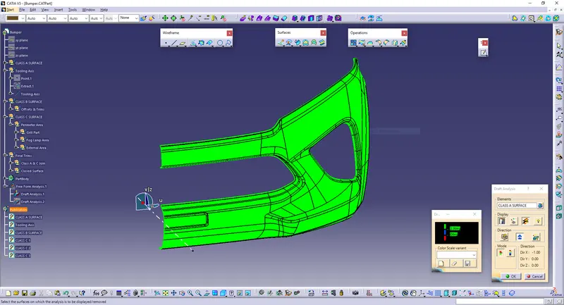
The green colour shows the positive daft tooling direction and the given surface passes the draft analysis.
Creation of Class B & C Surfaces:
Class-B Surface
It is the offset of the class-A surface at a particular distance. The offset distance depends on the thickness between Class A and Class B surface.
Here, the thickness given = 3mm.
Procedures to build class B surface:
- Offset the joined class-A surface to 3mm inward direction.
- Rework on the patches and discontinuity of the offset surfaces using the features like extract, multi-extract, sweep, multi-section surfaces, extrapolate.
- To ensure the continuity of the Class-B surfaces check the boundary command to find out the boundary.
- Hence class-B surface creation is done.
Class B surface offseted 3mm is given below:
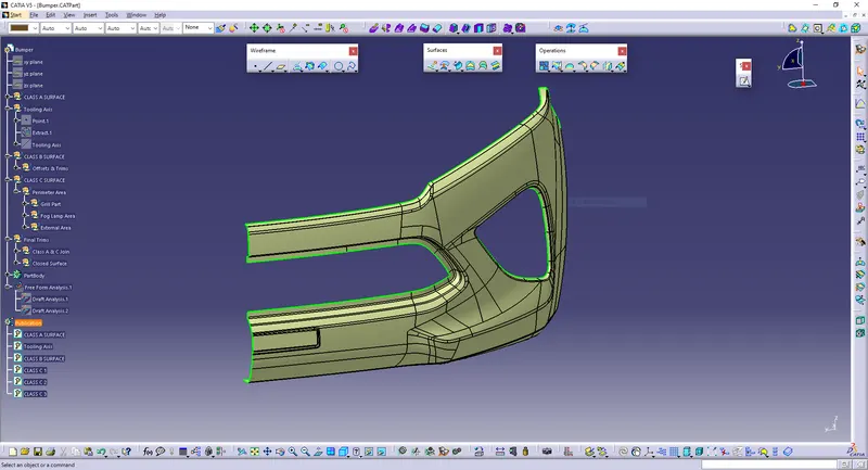
Class-C Surface
This surface connects the Class A and Class B surfaces. (Surface in between Class A & B surfaces)
Procedure to build Class C surface:
Since it is a complex class-A surface, we cannot simply create the class-A boundary curve and sweep it at one shot. Hence, we need to create smaller curves using boundary command and then create sweep of 90 degree with reference to the surface option. Sweeps at the grill area of the bumper should have a 3 degree draft vaue with repect to tooling axis to pass the draft analysis.
Join every induvidual sweeps using join command and for the edges which hasn't joined, extrapolate and trim off the sweep surface corners at the required edges.
The Class-C Surface:
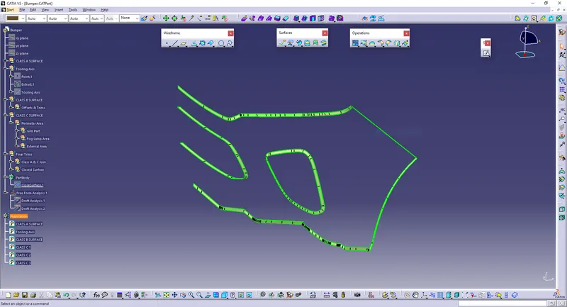
Final Surface Creation
Joining and Closing of Class A,B & C surface:
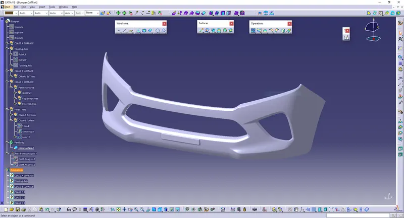
After creating class B & C surfaces joining operation is done between class A and class C surface. Then, Class B surface is trimmed with joined Class A & C surface to get a whole closed single surface.Then, the whole surface is mirrored using symmetry command to get whole bumper. Then in part workbench using closed body command, a solid body is generated.
Closed surface:
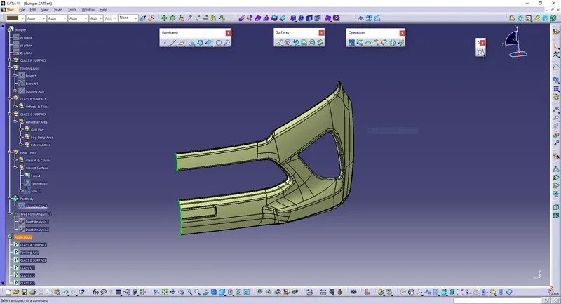
Closed symmetry surface:
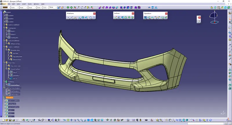
Solid Body:
Draft Analysis - Final Solid Body
Same procedure for the draft analysis of CLASS-A surface is followed.
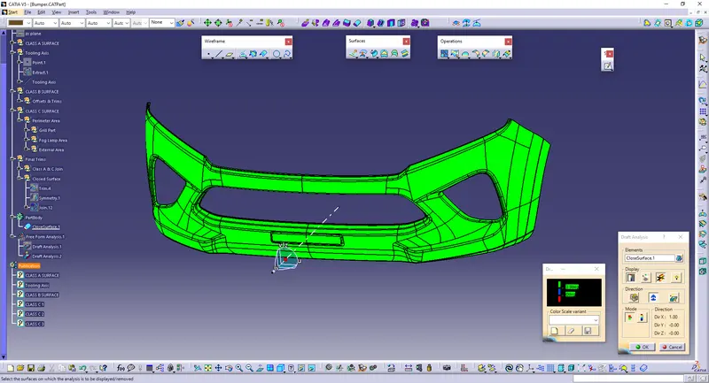
Hence draft analysis is done and from that it is understood that the part is completely manufacturable.
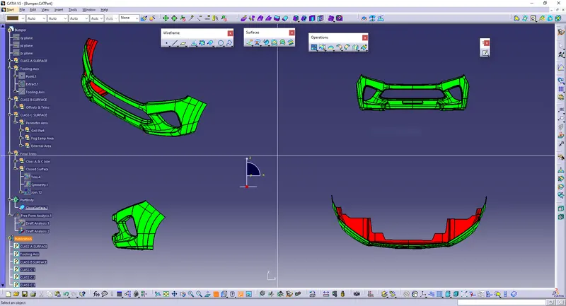
Screenshots of the solid model with the proper color code of the draft angle in various orientations:
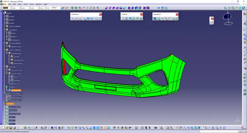
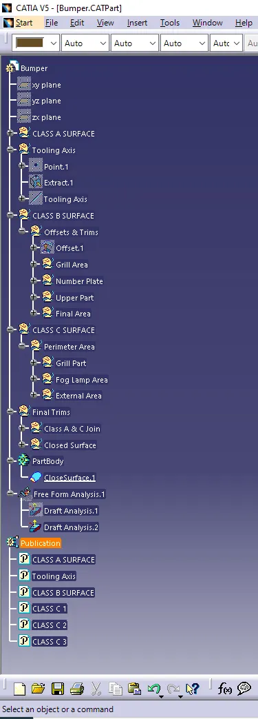
Tree:
CONCLUSION
Tooling axis is created properly for the given class A surface and based on that class B & C surfaces are made. Draft analysis is done for the class A surface and final plastic component and the results were obtained.