Week 9 - Attachment Feature Creation - Challenge 1
Aim: To design ribs on the coin holder considering every design rule considered in industry.
Theory:
- Class A surface: It is outermost surface of automobile which gives aesthetic look to vehicle. It is physically touchable. It is obtained from clay modeling by reverse engineering. This surface is given input to plastic product designer to work.
- Class B surface: This surface is created by taking offset from class A surface. It is surface on which all engineering feature like screw bosses, dog house, ribs & mounting are created.
Ribs Design:
Ribs provide a means to economical stiffness & strength in molded parts without increasing overall wall thickness. They also facilitate,
- Locating & arresting components of an assembly:
- Providing alignment in mating parts.
- Acting as stops or guides for mechanisms.
Proper rib design involves five main issues:
- Thickness
- Height
- Location
- Quantity
- Manufacturability
Consider these issues carefully when designing ribs.
Design rule for rib:
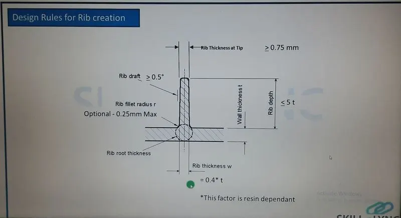
- Draft angle:
There should be minimum 0.5 degree draft per side on ribs provided. It allows the rib to release from the mold. But care should be taken to maintain rib thickness at top. More draft angle reduces thickness at top.
- Thickness of rib:
W= 0.4*t
Measure base thickness of rib at tangent of radius if radii are modeled in
The larger the area at the base of the rib, the more heat retained. The retained heat causes more shrinkage, which causes sink.
- Height:
Rib Height < 5 x nominal wall thickness
It is limited by draft & thickness requirement.
- Rib thickness at tip:
Minimum thickness at rib tip should be 0.75 mm. otherwise material will not reach at the tip of rib properly.
- Rib fillet radius:
Optional rib fillet radius is 0.25 mm maximum.
Do not want to significantly increase rib thickness. It must not violet 40% thickness requirement.
- Rib root thickness:
Rib root thickness should not be more than 30% wall thickness to avoid sink marks.
Root thickness ≤ wall thickness + 30% of wall thickness.
- Spacing between two rib:
Rib should be spaced so that steel between the ribs is at a height /width ratio 3:1. Whereas 2:1 is preferred. Prevents thin steel conditions which lead to cracking
Design approach:
- Creating a rib profile:
Extract the bottom base surface of coin holder i.e. B side.
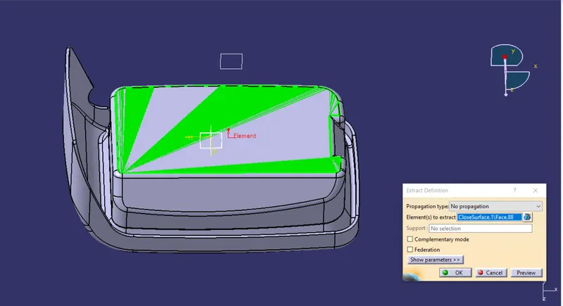
Draw a profile of rib. Sketch a line on ZX plane & sketch should be positioned.
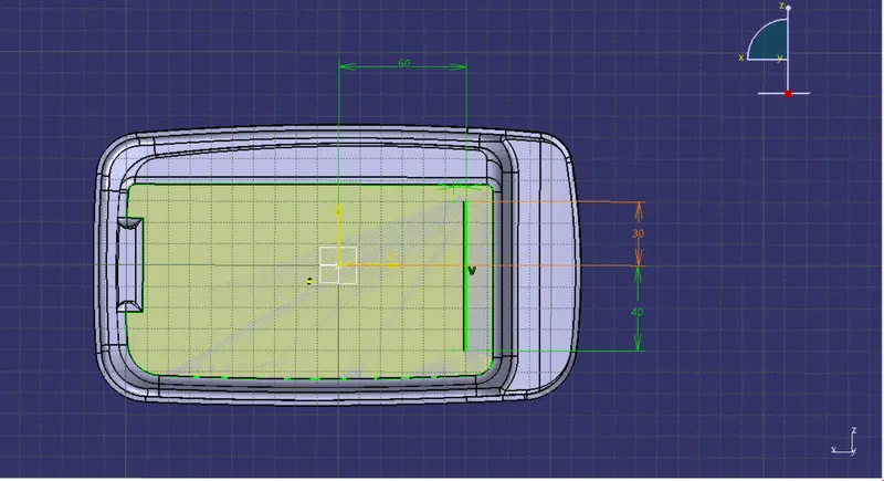
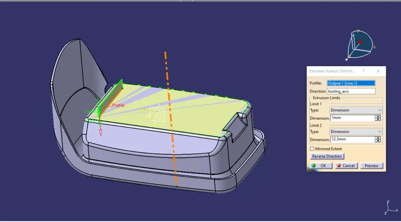
- Height of rib:
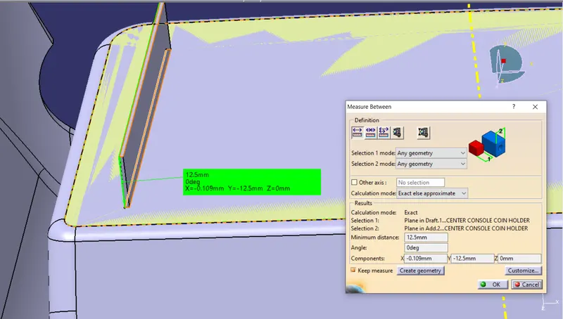
As per design rule, height of rib = 5* t. Where, t (wall thickness) = 2.5 mm.
Ht. of rib = 12.5 mm.
So extrude the line created along tooling direction 12.5 mm in upward direction & keep 1mm in other direction to ensure there is no any gap.
- Thickness of rib:
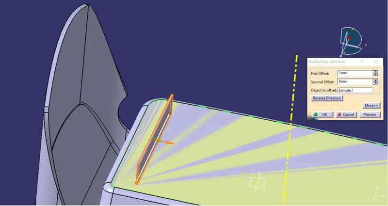
Go to part workbench & add thickness to extruded surface. As per design rule,
Thickness of rib = 0.4*t where t is wall thickness of coin holder.
Thickness of rib = 1 mm.
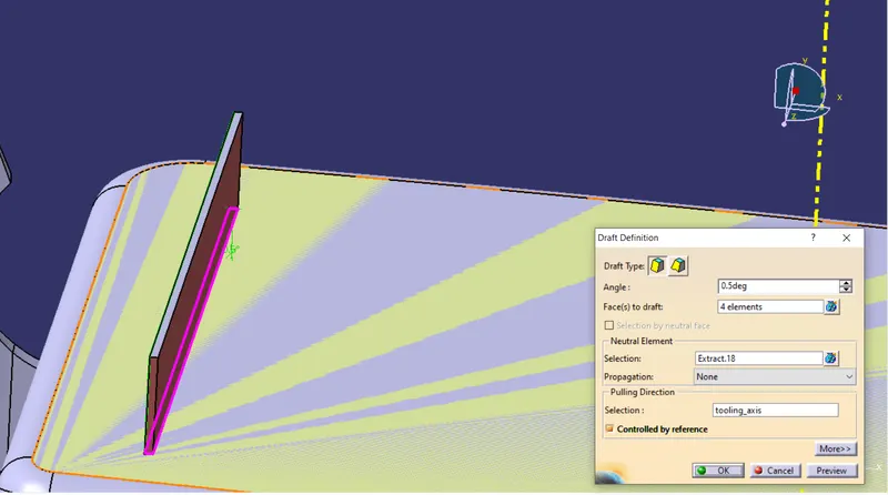
- Draft on rib faces:
Now add 0.5° draft to all vertical faces of ribs by taking pulling direction as tooling axis.
- Thickness at rib tip:
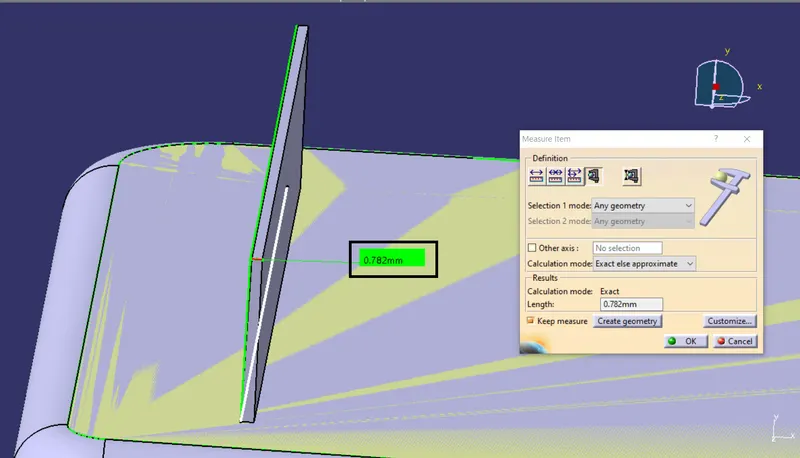
Measure the rib thickness at top. Minimum thickness at rib tip should be 0.75 mm. So in our design 0.782 mm is good.
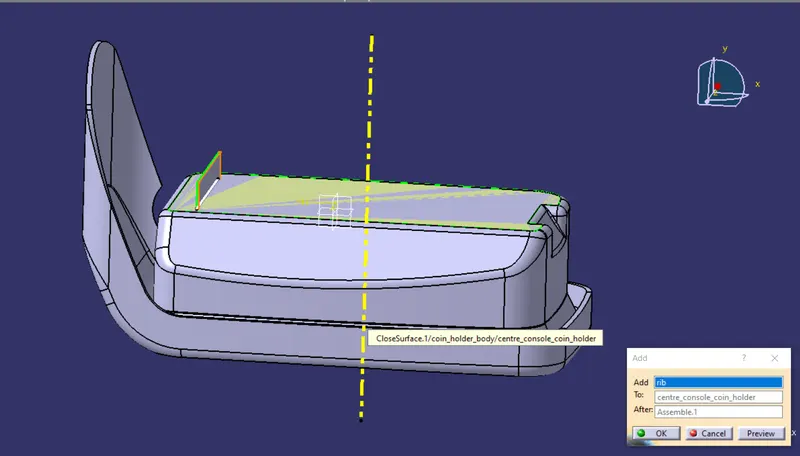
Now add rib to coin holder body.
- Optimal radius:
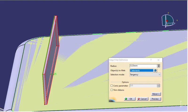
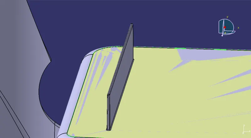
Now add 0.25 mm fillet radius on all edges of rib.
- Rib root thickness:
To measure rib root thickness, take a reference plane at the middle of part.
Then take intersection of coin holder body with plane.
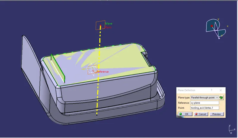
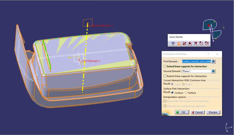
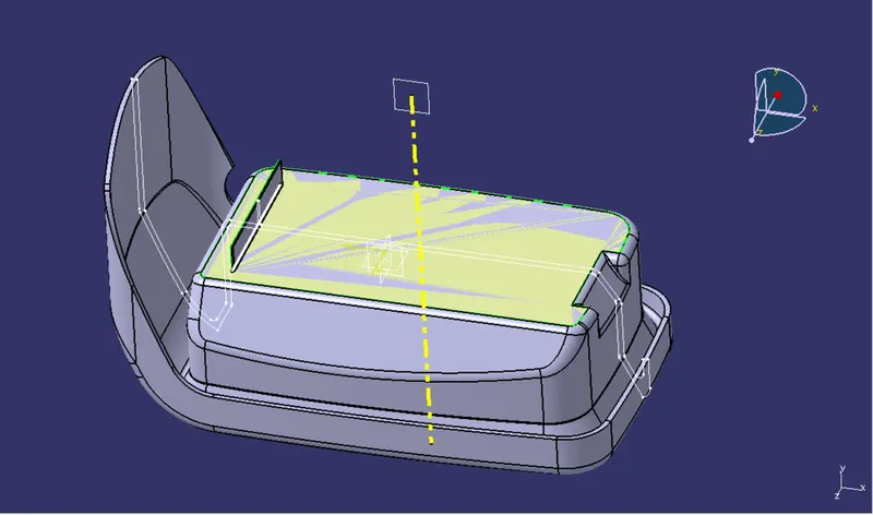
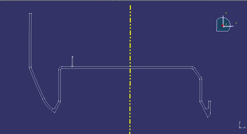
Draw a tri tangent circle at rib root as shown in below image.
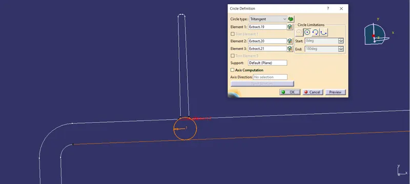
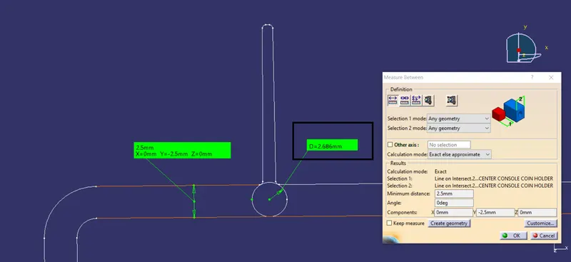
Let’s make calculation, we know that thickness component is 2.5 mm &
Root thickness ≤ wall thickness + 30% of wall thickness
So, Rib root thickness = 2.5 x 1.3 = 3.25 mm.
We got diameter value as 2.686 mm from measurement. This is within limits.
- Spacing between two ribs:
Height/ width (x) ratio= 3:1. Where, (x) is unknown.
We know height of rib = 12.5 mm.
So steel width (x) = height/ 3 = 12.5/3 = 4.167 mm
So keep it as 5 mm for safe side.
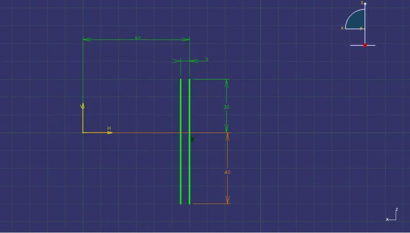
- Making second rib
Repeat the same procedure as above to make second rib & measure spacing between two ribs. But we get value 4.004 mm this is less than 5 mm because we have not considered thickness of component.
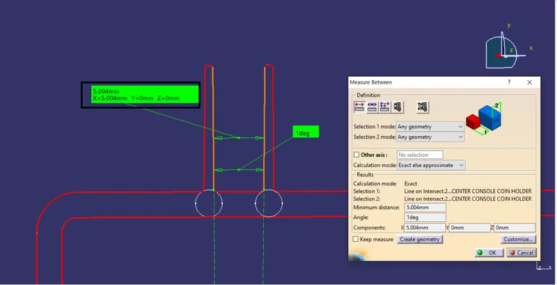
Increase the distance between the two lines in sketch to get 5 mm gap between two ribs.
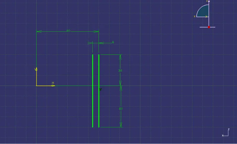
Performing draft analysis on ribs
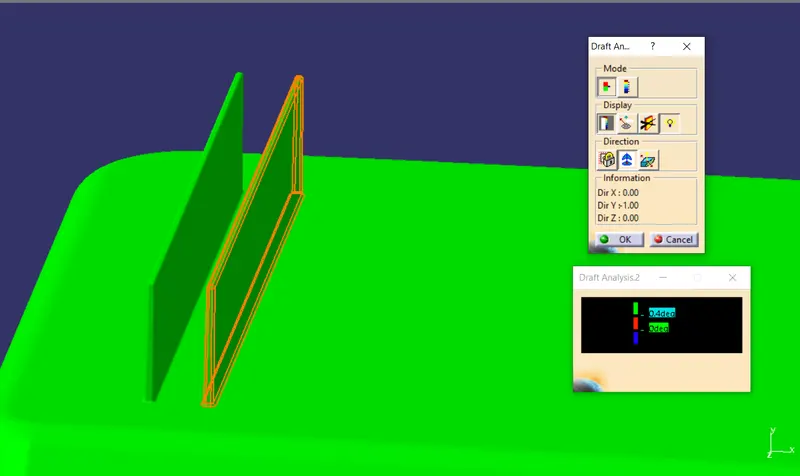
- To perform draft analysis. Go to insert < Analysis< Feature draft analysis.
- Switch customize view parameter mode to
- Click on compass icon & align it with the tooling axis & click on the surface, we will get our results.
- From the below image it is seen that surface in green color has more than 0.4° draft.
- Various orientation of component:
ISO view
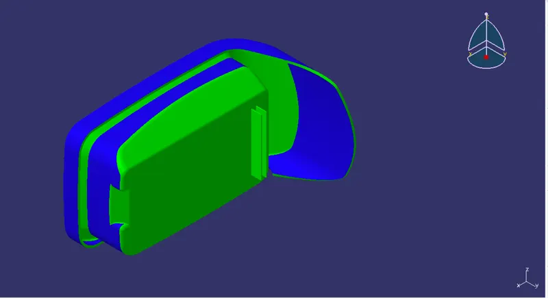
Front view:
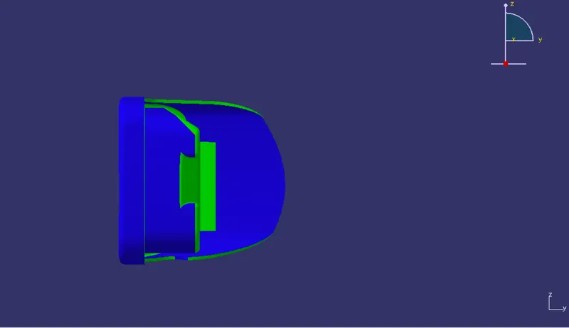
Top view:
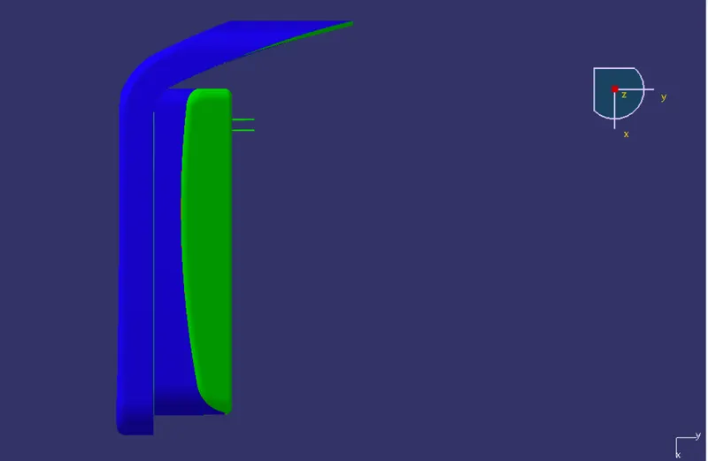
Left side view:
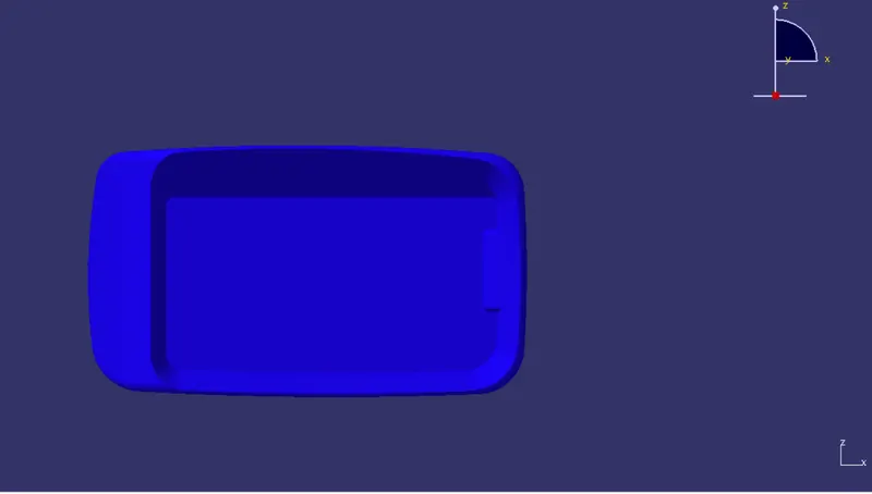
Right side view:
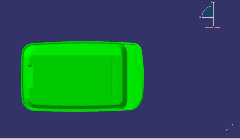
- Image of the expanded tree structure for the geometrical sets & part body.
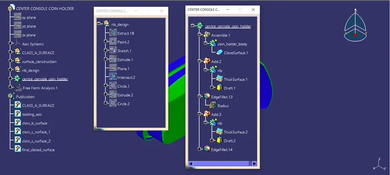
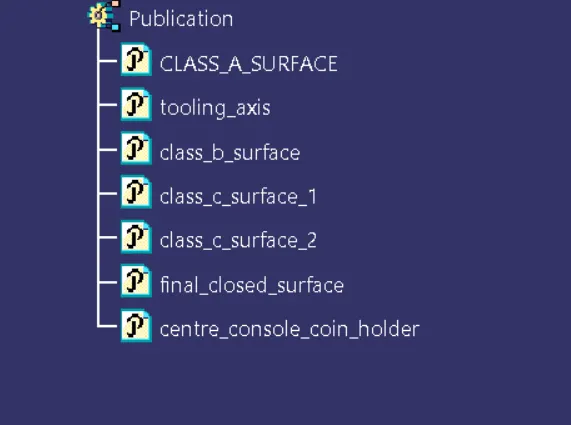
- Image of the publications of tooling axis & class A, B & C surface.