Week 9 - Attachment Feature Creation - Challenge 1
What is a Draft analysis?
The Draft Analysis command enables you to detect if the part you drafted will be easily removed. This type of analysis is performed based on color ranges.
the first thing is to check the connectivity of class A, And ensure that there is no gap between the surfaces you can check it visually or select the boundary option.
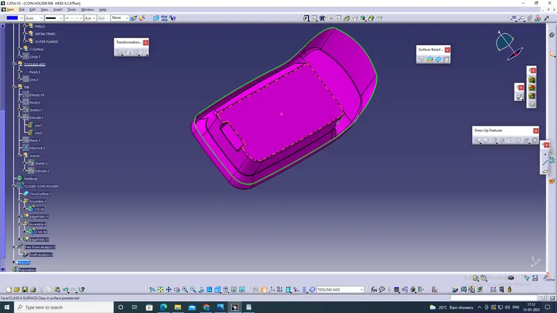
The second is to find the tooling axis
what is the tooling axis,
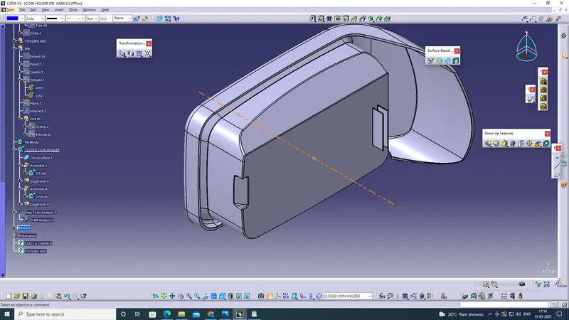
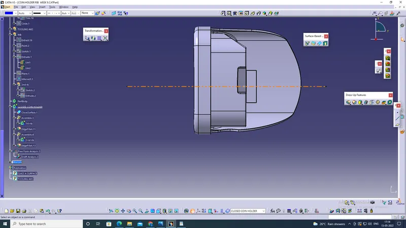
The tooling axis is the direction in which the mold opens or a cavity opens fine to decide the tooling axis the component should completely clear the given tooling axis in the given specific direction.
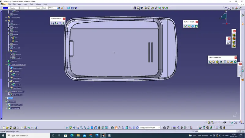
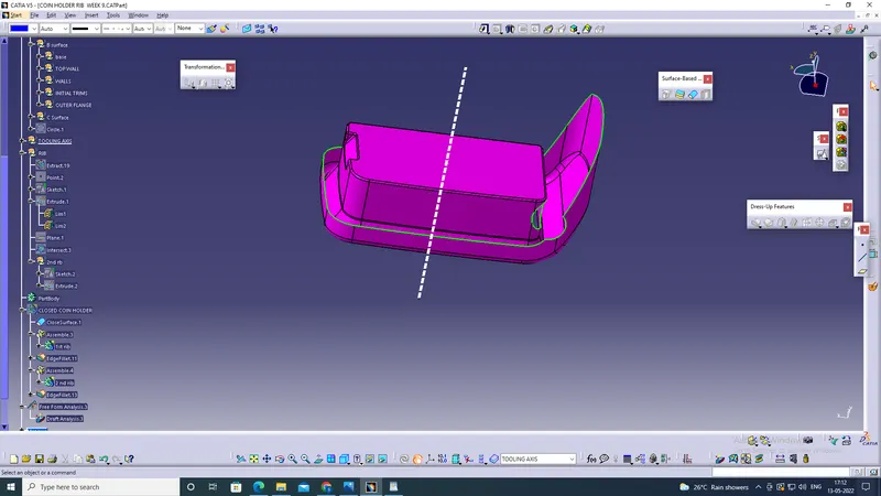
and next, we are going to check, which is the best possible. tooling directions we will check all three XYZ directions. the first one along the y-direction and the second one along X, so X and Y direction and z is going to the tooling axis. instead of creating the planes, I will insert the axis system at this point.
Creation of Class B surface
We will be creating the B Surface with the help of the A surface, first will be extracting the surface from the surface will be creating an offset,
of 2.5 mm and will be creating a complete b surface by using tools like, extract, offset, and trim ... after we create the B Surface will be now creating the C Surface
C surface Creation
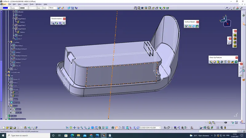
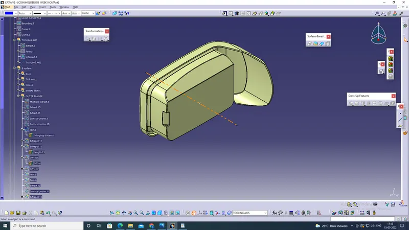
We will create the C surface using the A surface, and with help of the tooling axis, first, we will take a boundary of the A surface, and then we will sweep along the tooling axis . then After the creation of the C surface, We will be joining the Class A surface with Class C Surface, and then after we join the class A And Class C...
Then we will be trimming it with the B Surface ... and then we will be getting a closed Surface and with the help of the closed surface tool we will be converting the surface model to the solid model...
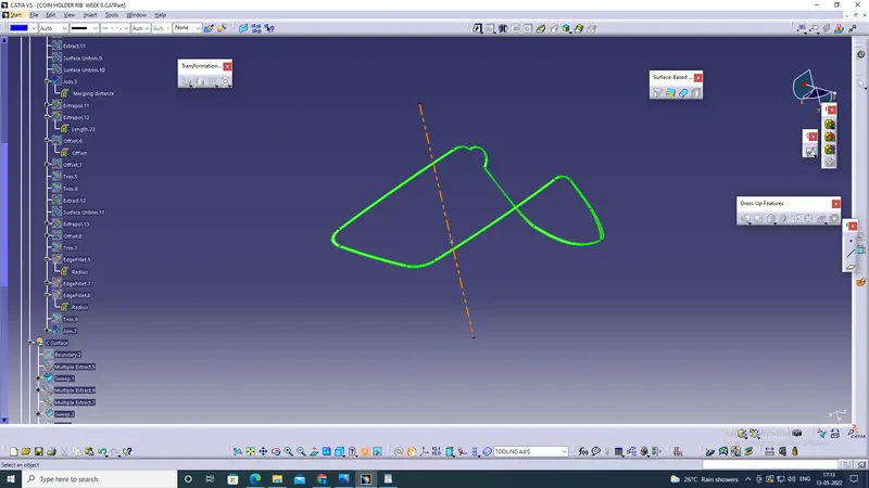
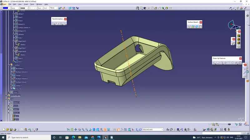
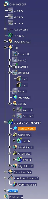
After the creation of the closed surface now we will be creating the Ribs according to the design rules
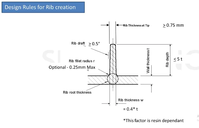
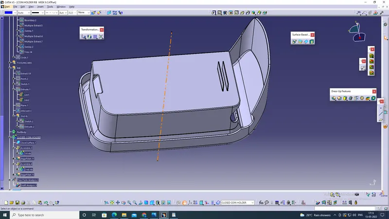
and after the ribs have created we will be verifying it by taking an intersection,
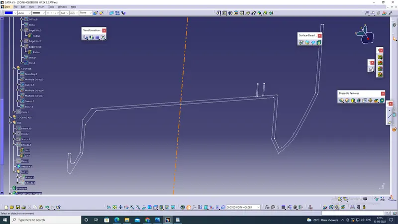
and after the creation of ribs now we will be performing the draft analysis,
To start doing the draft analysis, you have to insert the feature draft analysis from the toolbar, then change the view mode customization to the material mode, and then start the draft analysis,
when you click the draft analysis you will get a dialogue box, in which you will have the direction tab that uses the compass tool,
place it on your tooling axis. and click the component
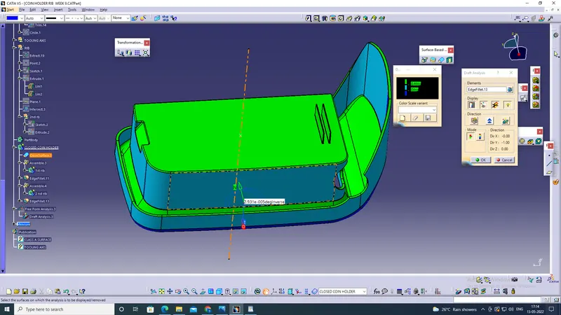
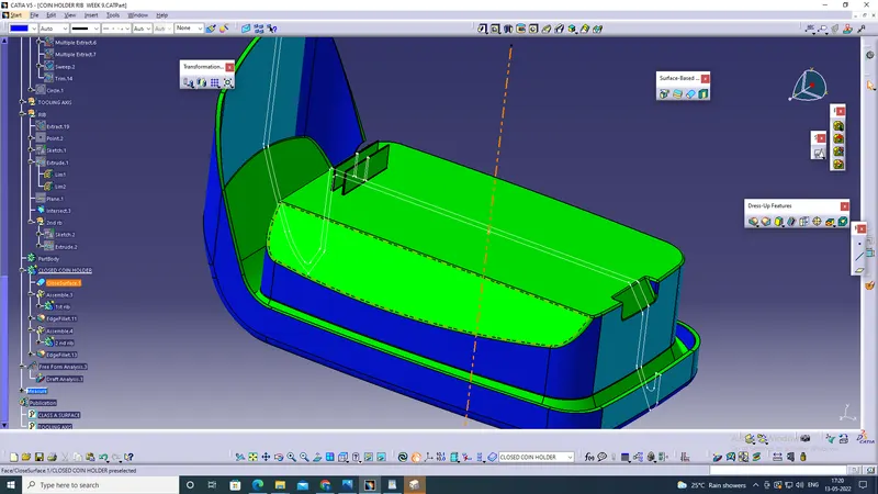
After that, you can see the change of color in the model, and in the draft analysis tab you can see the Degree Value according to the color, and then if you want to check the on a specific point you can use the running point tool in the Display tab and can check the degree at the specific areas.