Week 9 - Attachment Feature Creation - Challenge 1
Rib Design
Ribs provide a means to economical stiffness and strength in the molded parts without increasing overall wall thickness.
Uses of Ribs
- Locating and arresting components of in assembly
- Providing alignment in mating parts
- Acting as stop or guides for mechanisms
Creation of Rib Design
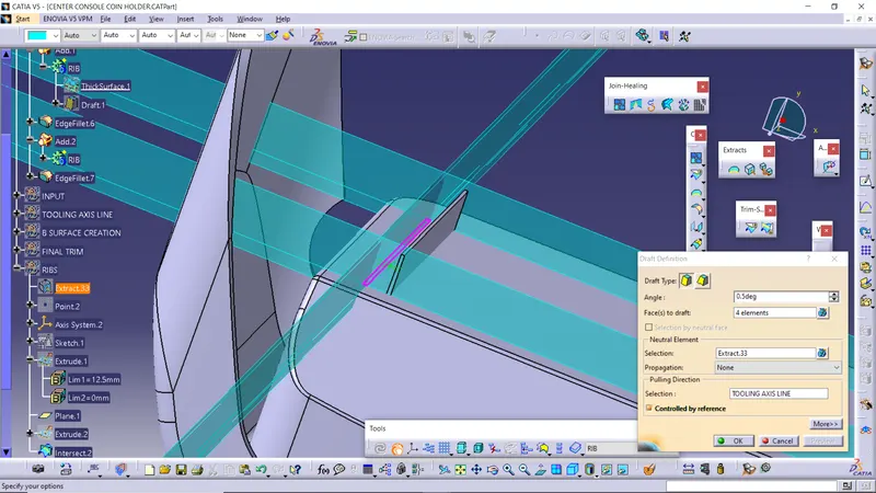
- Draft: A draft of 0.5 deg is provided on the both side of the rib to ensure easy removal from the mold
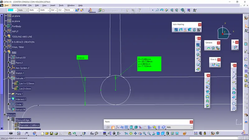
- Thickness: It should be 40% of the wall thickness of the component
- Rib height : It should be five times of the wall thickness of the component
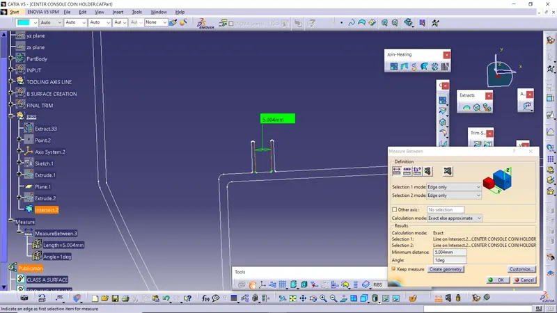
- Rib spacing: It should follow height of width ratio of 3:1
- Mimimum thickness at the rib: It should be 0.75mm
- Fillet : It should be of 0.25mm
- Width : It should be 0.4 times of the thickness
A draft of 0.5 deg is provided on the both side of the rib
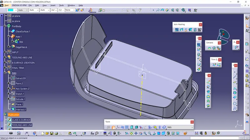
It should be 40% of the wall thickness of the component
Rib spacing: It should follow height of width ratio of 3:1
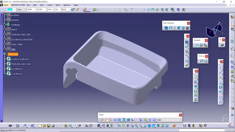
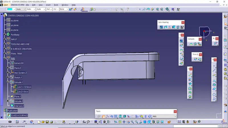
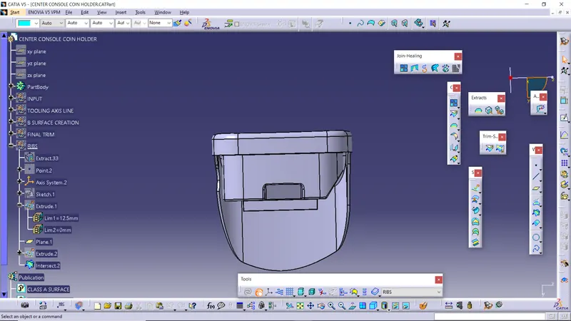
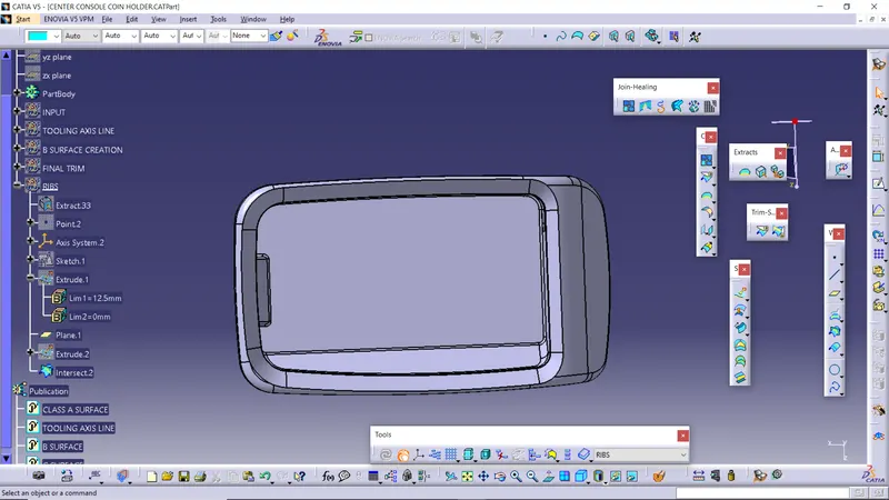
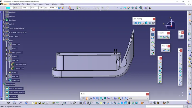
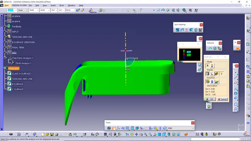
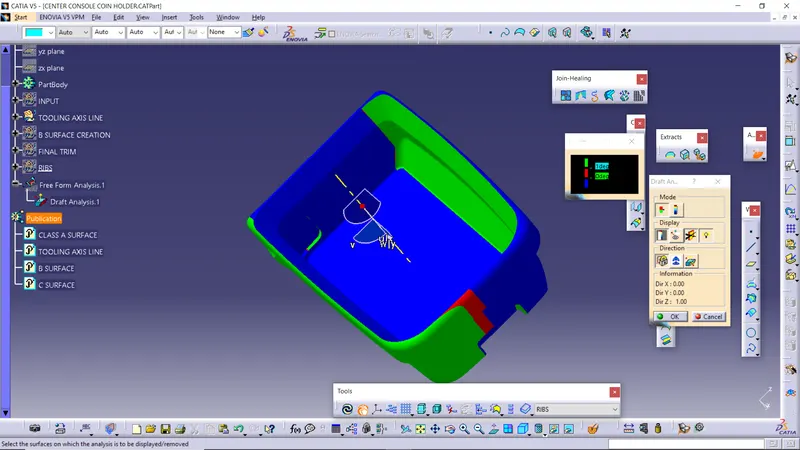
Draft analysis Report
- The green colour represent the angle of surface with respect to tooling axis being greater than 3 deg
- The blue colour represent angle between 0 and 3 deg
- The red colour represent the angle lesser than 0 deg