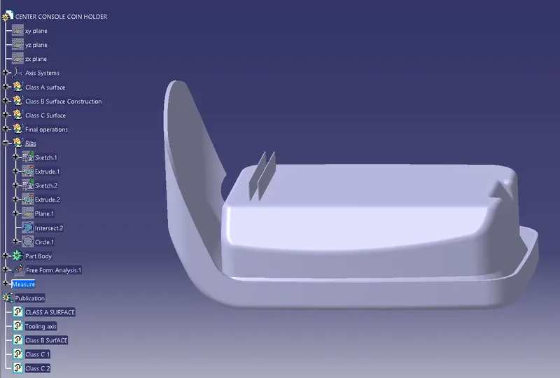
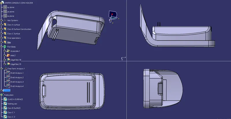
Week 9 - Attachment Feature Creation - Challenge 1
Aim :
To Create the rib for the Centre console coin holder considering the design rules mentioned in the video.
Ribs :
Ribs are added to increase the srength of the material. Since plastic surfaces have ;low strength at many placwes considering its wall thickness, in this case ribs will act as the strength providers.
Generally creating ribs is not a simple procedure. Ribs can create defects in the plastic body surface like sink marks which will occure on the visible side of the plastic body.
Guidelines for rib creation :
- Draft angle
- Height
- Thickness
- Spacing
- optional radius
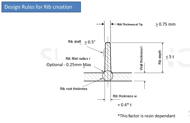
Draft :
Draft is providing any surface with angular deviation. Basically drafts are given for easy acces of the part removal. Without draft there will be many defects that must be taken into consideration.
0.5 deg of minimum draft angle is given on the side faces of the rib.
Height : (h)
Second factor considered in rib creation is height of the rib. Taller the rib less the strength and more the cost of production. Hence a formula is used for rib hieght consideration.
h ≤ 5 * T . ( T = Wall thickness of plastic component )
Thickness : (w)
Thickness of the rib is the next factor taken into account. Hence the thickness of the rib should not exceed 40% of the wall thickness of the component.
w = 0.4 * T . ( T = Wall thickness of plastic component )
Rib Tip Thickness :
Rib thickness at the tip after drafting should be of 0.75 mm minimum. Hence the rib wall thickness at the bottom will be of larger than the top.
Rib Root Thickness :
Rib root thickness will be the major factor determining the sink mark more the RRT probability of sink mark is also high.
RRT = T + w . ( w = 0.4 * T ) .
Spacing : (s)
Spacing will be determined based in the height of the rib. Such as 3:1 for steel and 2:1 is generally preferred.
s = h / 3 .
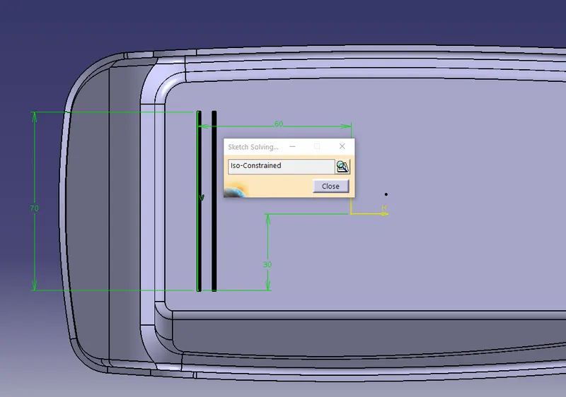
Step 1 :
Sketch for the rib is created and checked for the iso-constrains. Which is basically line with dimensions.
Step 2 :
The sketch for the rib is then extruded using the surface extrude command. This is then thickened using Thickened surface command on surface design toolbar. Considering the spacing formula a new rib is translated to the required spacing dimension.
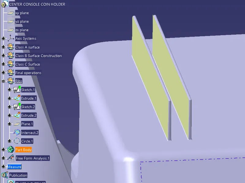
Step 3 :
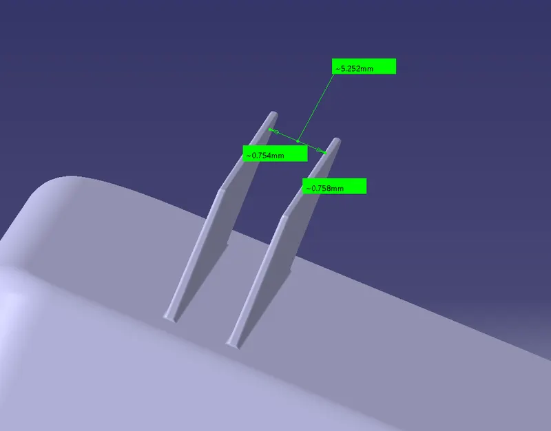
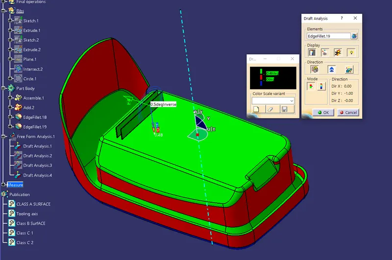
Draft of 0.5 degree is given for all the side faces of the ribs created. Then the rib tip thickness is measured to verify the thickness at the tip is lying within the design nomenclature or conditions. Here the thickness after drafting is 0.75 mm (app) at the tip.
Step 4 :
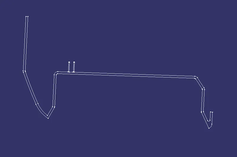
Intersecting line for the coin holder along with the rib is created to check the rib root thickness.
Step 5 :
A tir tangent circle is drawn in the space between the bottom of the tip and A surface line. For creating tri tangent circle we need to extract the required sides. And the radius of the circle is measured.
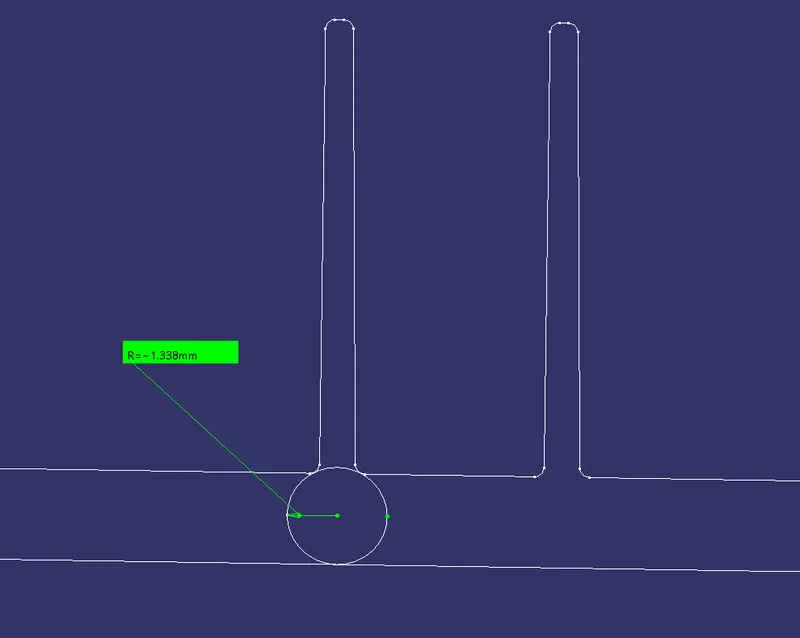
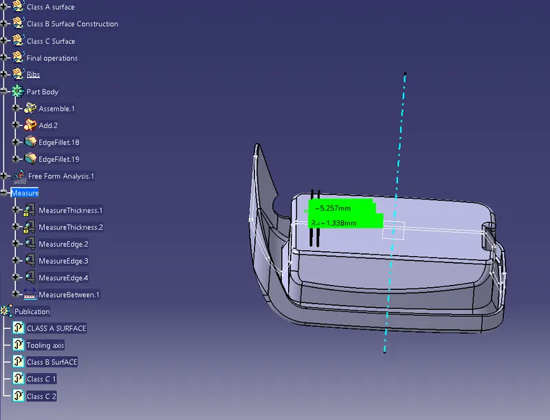
The below diagram shows the required parameters such as the thickness , spacing between the ribs and the rib root thickness.
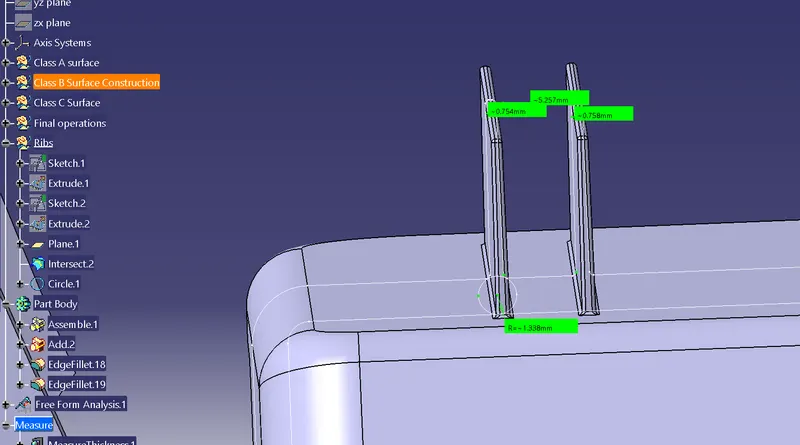
Step 6 :
Draft analysis for the ribs created is verified by using Insert - Analysis - Feature draft analysis command. Here the draft angle on the side faces of the ribs are above 0.5 degree.
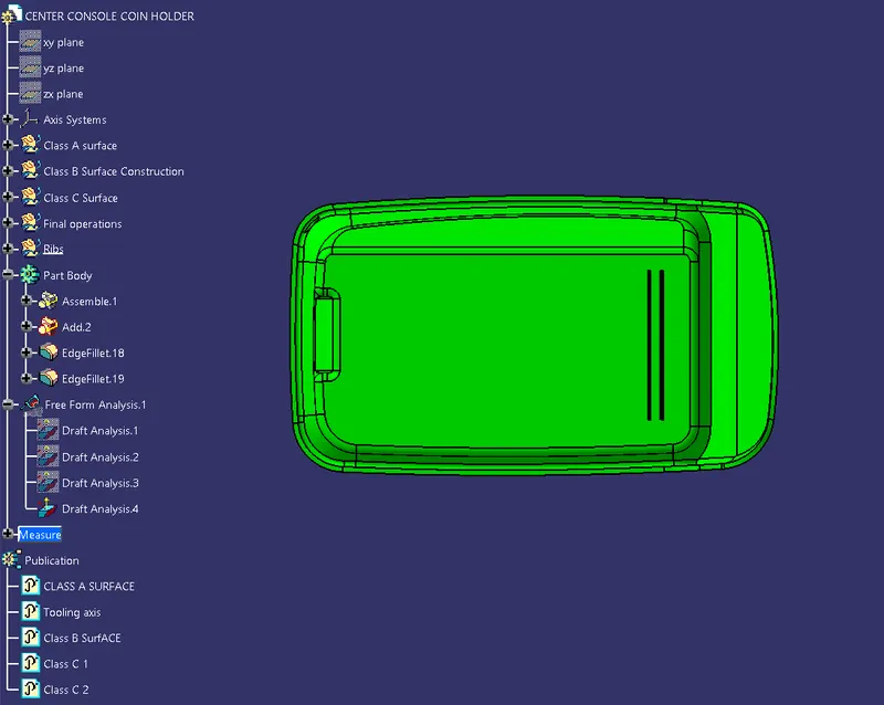
The final part body is displayed along with required tree structure. Since Class B feature are additional ones they are created under the boolean operation which involes creating a new part body for the rib and then adding or assembling the ribs with the part body.