Week 9 - Attachment Feature Creation - Challenge 1
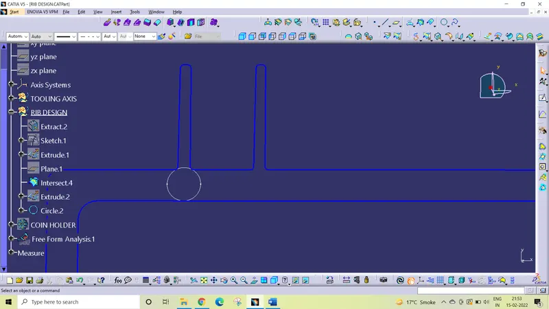
OBJECTIVE: To Create the rib for the Centre console coin holder considering the design rules and perform draft analysis.
Introduction
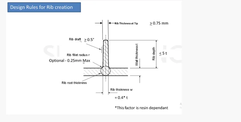
The position and orientation of a rib relative to load and reaction forces is critical to its effectiveness. By being conscious of part geometry, designers can ensure that ribs added to the design will improve bending stiffness. Here are some rules of thumb to keep in mind during the design process:
Rib thickness
Ribs should be designed to be 50-60 percent of the nominal wall thickness. Thinner does not provide much structure and may be hard to fill. Thicker ribs are tempting, but they can begin to introduce sinks on the cosmetic surface.
Rib height
For maximum effectiveness, rib height should be no more than three times the nominal wall thickness. Since the rib will be thinner than the wall, it may be hard to fill it if it is taller.
Rib spacing
Increase the number of ribs rather than their height in order to increase stiffness. Ribs should be spaced a minimum of two times the nominal wall thickness apart from one another.
Rib draft
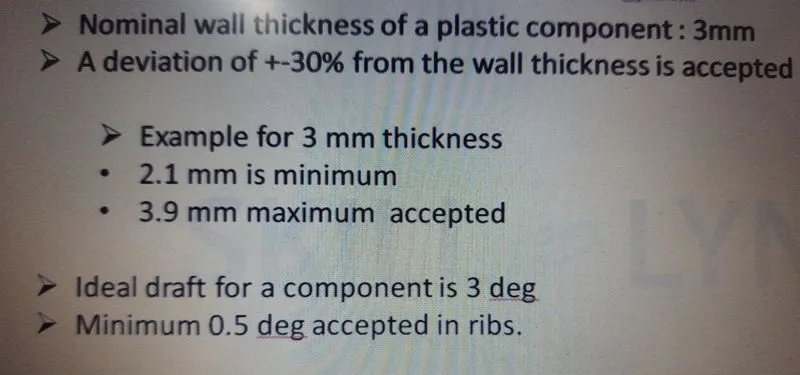
A minimum 1degree draft will ensure that they release from the tool during molding.
Rib coring
Core thick ribs from the back or below to create a blank area and thinner rib walls. This will help mitigate cosmetic sinks.
Rib radii
Radii at feature intersections should be a minimum of 0.5 - 1.0x nominal wall thickness to increase rib strength.
STEP FOLLOWED
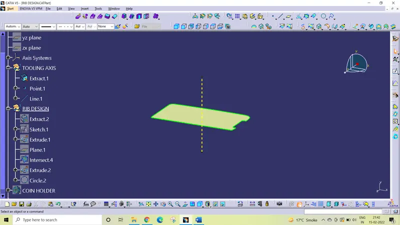
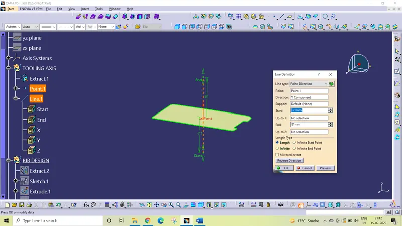
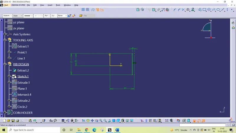
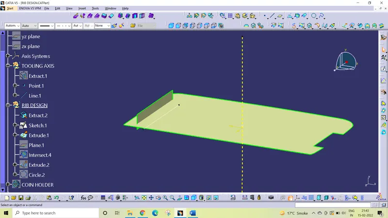
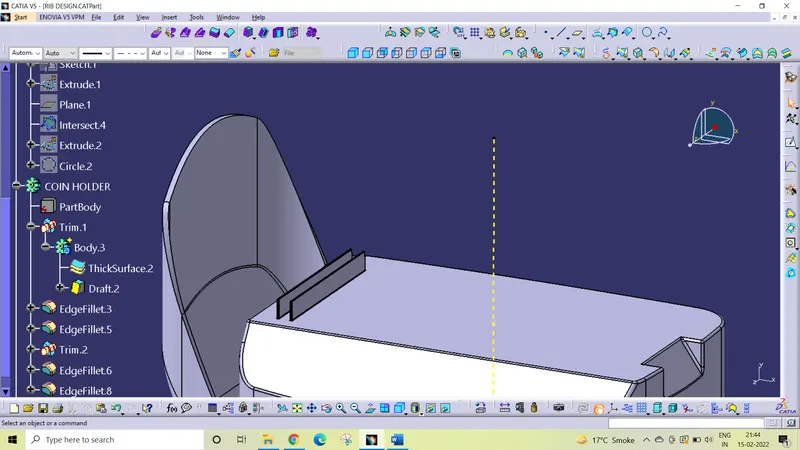
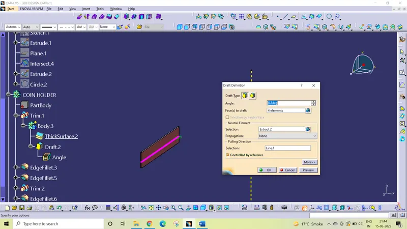
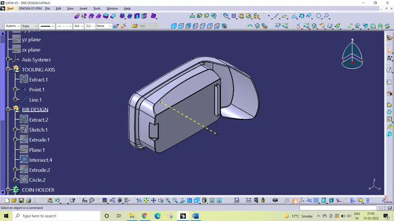
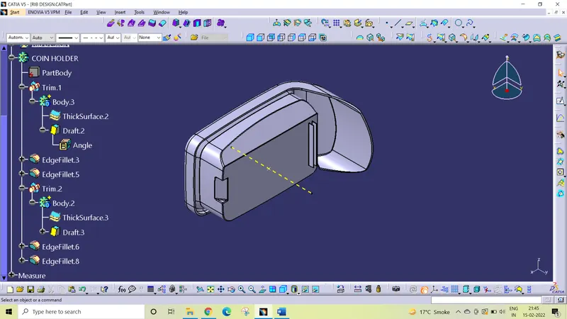
ISO VIEW
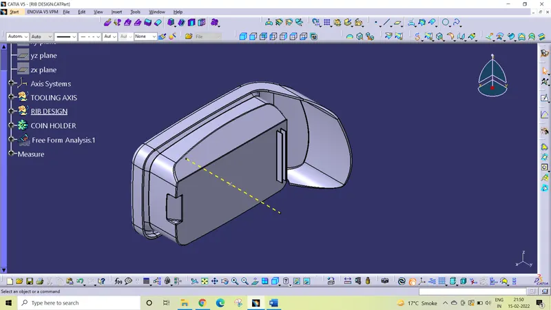
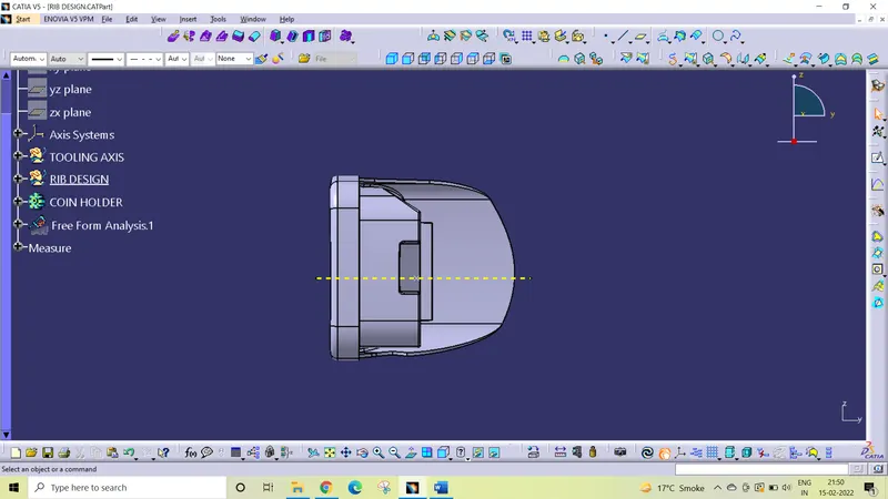
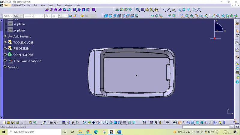
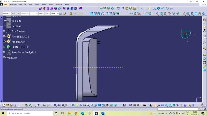
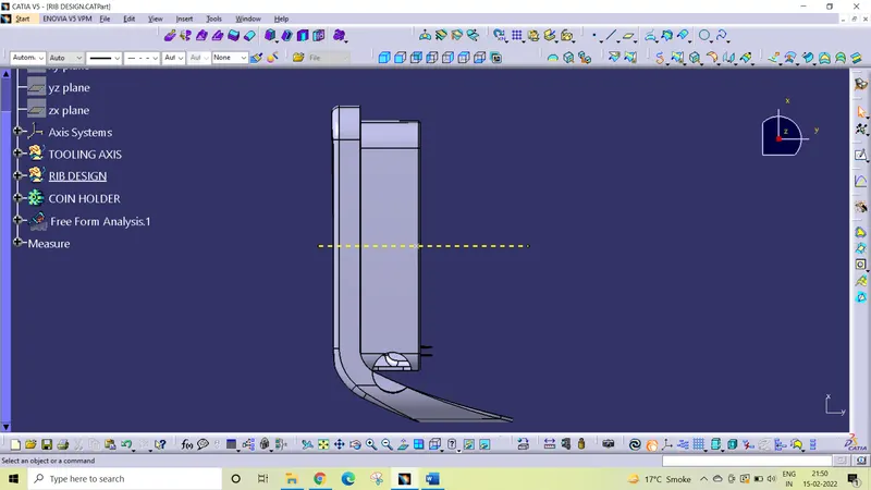
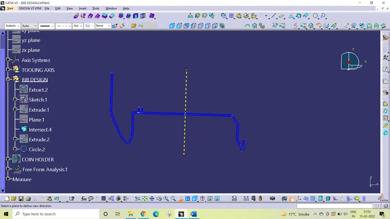
DRAFT ANALYSIS
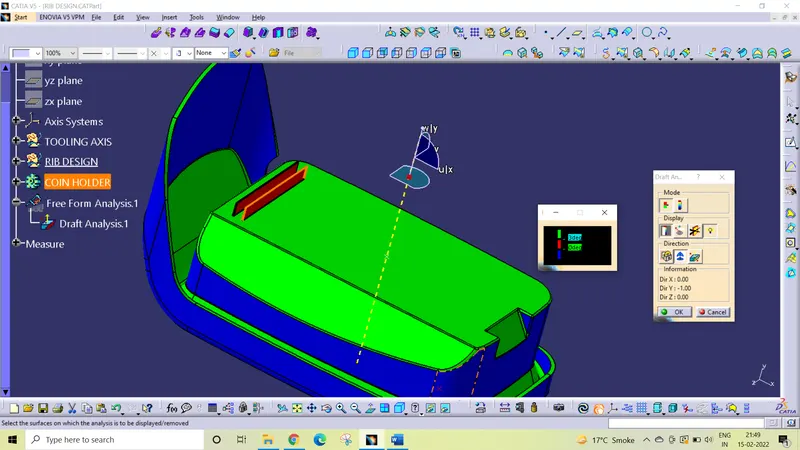
The Draft Analysis command enables you to detect if the part you drafted will be easily removed. This type of analysis is performed based on color ranges identifying zones on the analyzed element where the deviation from the draft direction at any point, corresponds to specified values.
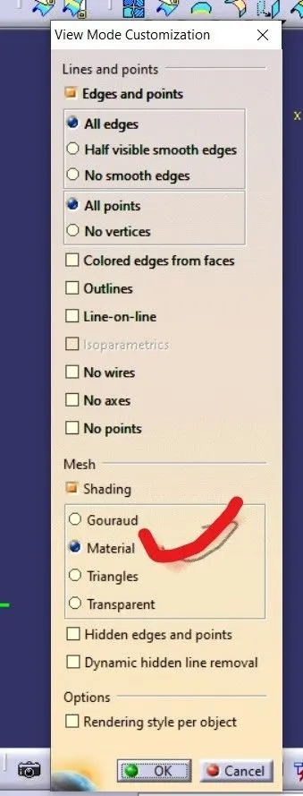
To perform the draft analysis on the bracket model, first set the view parameters to material mode.
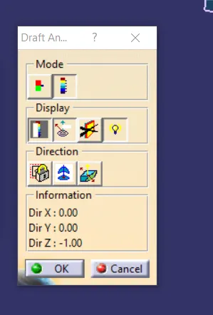
Then go to menu bar select insert analysis feature draft analysis
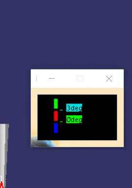
To give the draft direction, use compass and align Z axis of it with the final tooling axis for the coin holder model. Once it is properly aligned, lock the draft direction. Select the coin holder and it will show us the current draft angle of the model, set the draft value 3 degree under the color scale variant and press ok.
Conclusion
Coin holder component using Class A surface have been successfully created and draft analysis have also been performed for the same.