Week 9 - Attachment Feature Creation - Challenge 1
RIB FEATURE WITH COIN HOLDER
AIM:
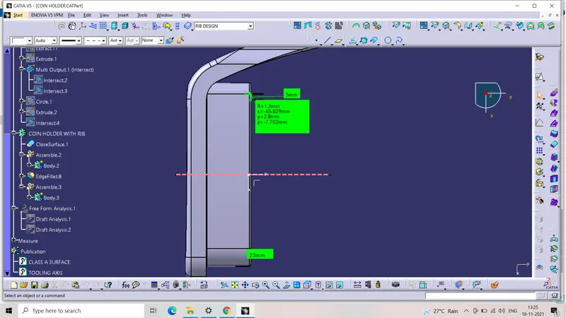
- To create the rib feature to the coin holder component and make the draft analysis for the feasibility in manufaturing.
OBJECTIVE:
- The engineering features rib on the B surface of the component considering the industrial standards and the manufacturing feasibility of the component.
B SURFACE:
- While the class A surface withholds the asethetic look and feel of the component to the user or the consumer,the B side is where the engineering features are made.Like the streghthening with stiffners,collars for the component ,mating slots and ribs are provided on the B surface.
RIBS:
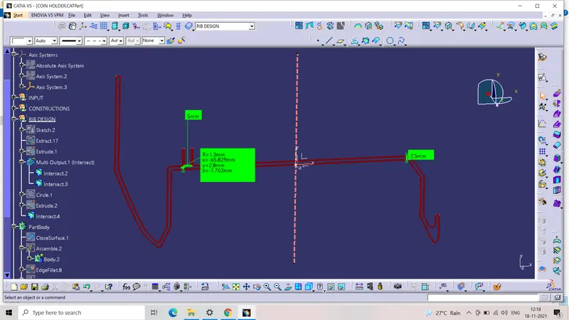
- The constrained sketch which is basically a line is created and dimensional values are provided to it.
- This line is then extruded along the tooling direction and then the design standard value for the rib height is computed and reflected back to the extrude length.
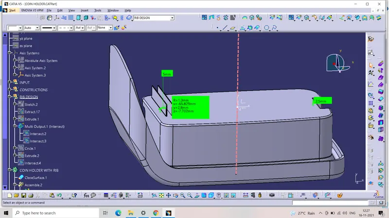
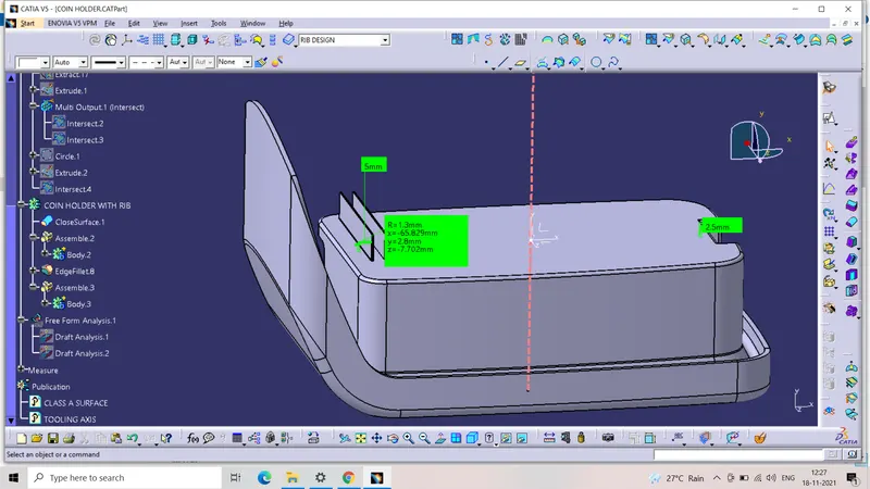
- The general equation is Rib height = 5*base thickness. Hence,the height is given as 12.5 mm since the wall thickness is 2.5mm.
- Then the surface is thickened in the part workbench.
- This value 1mm,is obtained by the equations, Width, w =0.4*t.
- Then the rib is assembled into the main part body.Fillets are defined for the rib.This is by the standard value of 0.25 mm to maintain the minimum tip thickness value of 0.75 mm.
- Then the second rib is created with same procedure and design aspects in hand.Then the intersection between the tooling axis plane and the ribs is taken and the rib wall thickness is measured by a circle tangential to the rib walls and the component surface.
DRAFT ANALYSIS:
- The draft analysis is carried out both for the component and the engineering features to ensure the feasibility and avoid the plastic defects after manufacturing.
- This procedure is carried out by creating the tooling direction at first.The bisecting method,where the bisection of the intersection component and the plane is taken.
- The bisecting line of the two opposing walls of the bin along the orgin point yields the tooling direction.
- The draft analysis for the component is pretty much undoable considering the draftless walls in the class A.Hence, a maximized tooling direction which clearing the surface is taken into account.
- The slider direction is provided to clear out the stiffner rear side and the side cut hole profile where it is a under cut.
- As we can see the draft angle is 0.5 degree which is the standard value for the internal features.
TOOLING DIRCETION:
- We will be creating the tooling direcction with bisecting method,for that we will have to check on x and z directions.Since here we have a bit different case because the part is oriented differently,what we have is that,its not having symmentery one of side/direction which is z,so we have to check manually for the direction,and determine that how the part will be clearing out.So now,since y is the main tooling direction (normal to base surface) which is achievable .So we have made a line normal to the extracted surface which is shown in light yellow colour.
CONCLUSION:
- Create the rib for the center console coin holder considering the design rules.
TREE STRUCTURES:
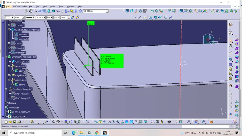
ISOMETRIC:
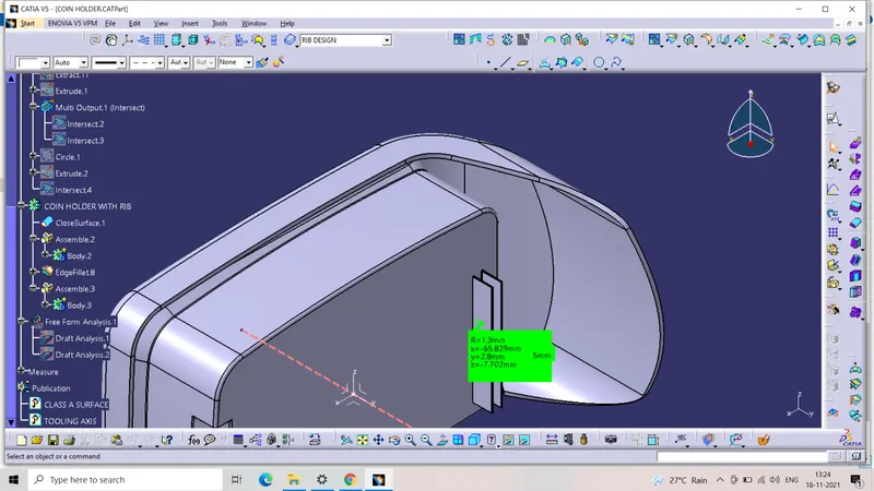
FRONT:
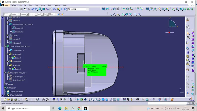
TOP: