Photo Realistic Rendering
RENDERING
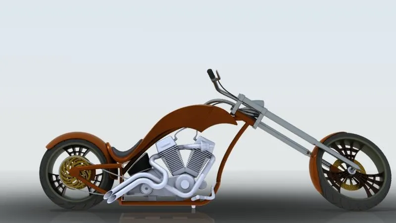
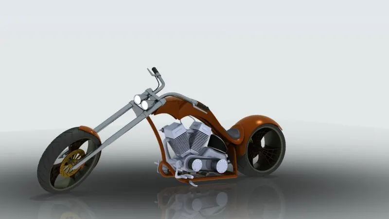
FRONT SIDE ISOMEDRIC SIDE
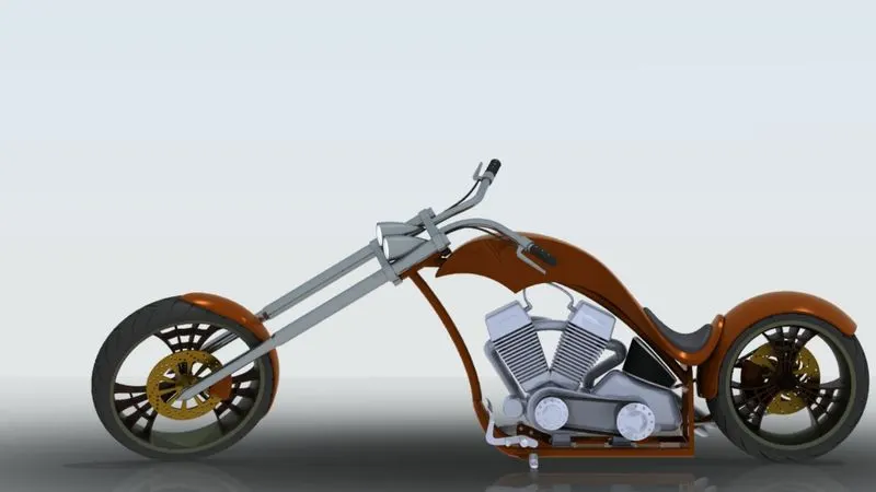
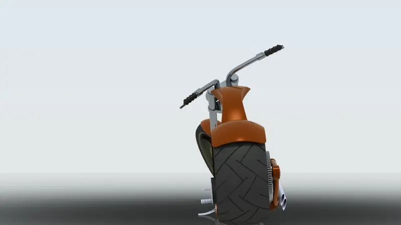
BACK SIDE LEFT SIDE
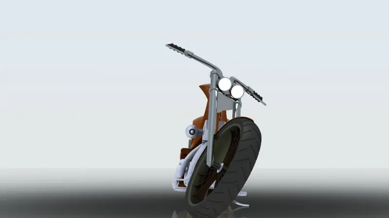
RIGHT SIDE
REPORT:
MODELING OF AMERICAN CHOPPER IN SOLIDWORKS
INTRODUCTION
In this project we are to learn the entire modeling of an American chopper on solid works.
The various components are using in the motorcycle, it to be listed below:
- Chassis
- Engine with exhaust system
- Front wheel and Rear wheel
- Front fork
- Front and rear fenders
- Oil tank
- Chain and transmission belt
- Kick stand and foot pedals
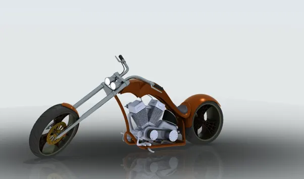
After designing the part components, we have worked upon the assembly and the photo rendering of the chopper which gives it a complete and realistic view.
DESIGN PROCEDURES:
Starting with the transmission belt and ending till the rendering section has been described step by step by means of a flow chart.
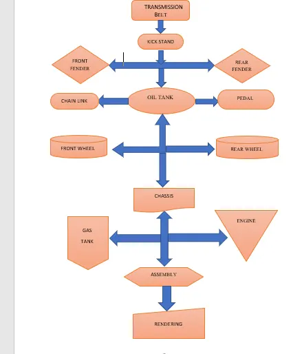
We will see in details about the features and properties are used in entire model to assembly of design parts:
EXTRUDE BOSS: The extrude boss features is the most important basis of solid works. It can be used for a sketch along a straight-line path to add materials. When the sketch has been created and exit the sketch select the features options in the command manager. Then click the extrude boss option. The yellow dialog box appears on the screen, it ask for a sketch. Don’t use it. Just only click on the graphics area to use it features. The Property Manager for the Extruded Boss allows you to control starting location, extrude depth and draft for the feature, among several other Parameters 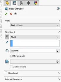
FILLET: Fillets serve to round off edges and/or corners by adding or removing material, depending on whether the edge is internal or external. It should be noted that fillets of different sizes must be created as separate features 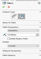
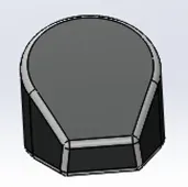
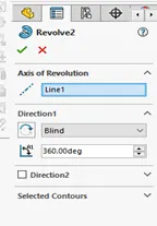
REVALVED BOSS: This options used to around the axis of sketch on add materials, once the sketch has been created, any flat face used as a sketching surfaces
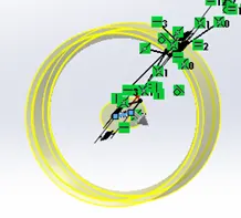
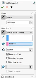
EXTRUDED CUT: This options needs to be sketch on the solid bodies which need to be a cut and desired shape
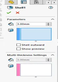
SHELL: Using this tool, you can make either completely closed hollowed model or one face opened type
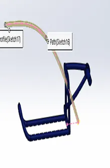
SWEEP BOSS/SWEEP CUT: Sweep boss makes closed surface base moving along the path of profile. Sweep cut used to open surface base moving along the section 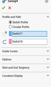
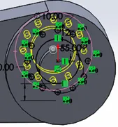
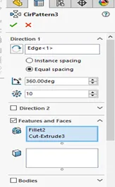
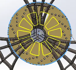
CIRCULAR PATTERN: This options create you can space uniformly along one or two circular paths
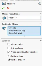
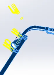
MIRROR: This options can be used for copy of multiple body features mirrored about a face or plane
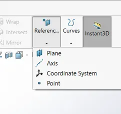
REFERENCE GEOMETRY: Reference geometry includes items such as planes, axes, coordinate systems, and points. It can be used for create several features such as loft, sweep etc
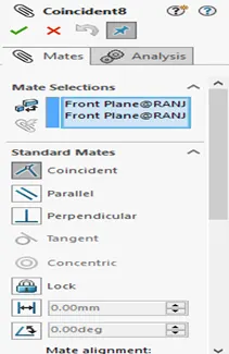
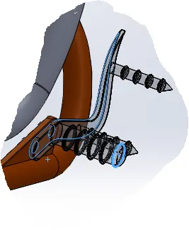
MATE: Mates include items such as coincident, concentric, perpendicular , tangent , parallel ,angle distance .This geometries are maximum used for relationship between assembly components. It can be move a component within its degrees of freedom, visualizing the assembly's procedures
LOFT BOSS/LOFT CUT: The loft feature creates a shape by making transitions between multiple profiles and guide curves. This tool is very valuable for modelling complex surfaces 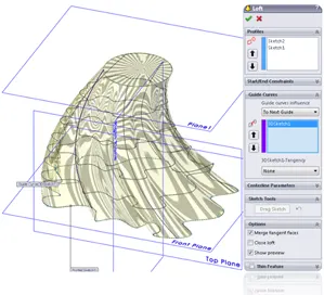
PROJUCTION CURVE: Click project curve on the curves tool bar or insert˃ curve> projected. Use this selection to project a sketched curve onto a model face.
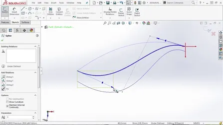
Now we have completed discuss about features. Let us discuss about the part details in mention flow chart.
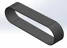
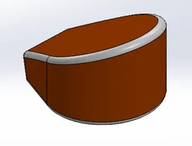
Transmission Belt: Transmission belt makes on the single extruded surface and outside edges are covert the fillets and also used appearance in matte rubber
Kick Stand: Kick stand create a sketch based on the additional plane, the sketch was created a loft part and use for a dome on both sides. Another sketch is draw and used for extrude cut options and also used for split features. At last one again draw a another sketch extruded and the cut the parts to be fillet. Used this appearance metal chrome plate
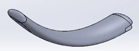
Front Fender: Revolved the sketch using the axis again is a single solid body where both the sides have been designed with the help of sketches and the split tool. The outer edges of the fender are filleted. It used for appearance in sienna painted

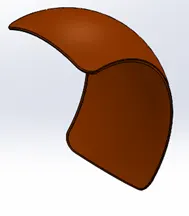
Rear Fender: In this part methods use for same as front fender. The only difference between the two are the sizes of both the fenders which vary accordingly with the size of the tire.
Oil Tank: The oil tank is sketch and extrude boss and also make another sketch to be use extrude feature. Combine the feature used fillet and shell
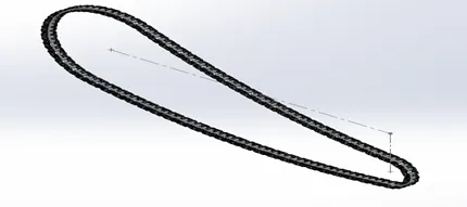
Chain Sprocket: Create a sketch for a chain layout. Select all sketch lines to create a continuous curve. Model the chain link profile and uncheck merge results for second link to the separate bodies. Mirror the bodies to complete the links. Use curve pattern to each of the chain link body along the sketch curve. The sketch curve length provide a number when divided by center distance of the links. At last appearance is used metal chrome plate
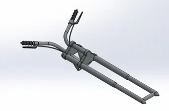
Front fork: Tools and features used for modelling are sketch, extrude, revolve, sweep, shell, dome, mirror, pattern, projected curve. First model one fixed rod by using revolved feature. Then model the half of triple tree by extruding and then patterning the counterpart. Then part of the axle is extrude and revolved to model the light. After this the handle is made by sweeping the circular sketch along the projected curve. The grip, brake and brake wire are model similarly with the reference of projected curve. Everything modelled should be then mirrored and combined
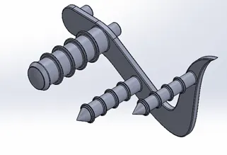
Pedal: In this part makes a tools and features used for sketch, extrude, revolve, dome, pattern, fillet, chamber. First draw the basic shape of pedal in sketch and then extrude it. Then sketch the circle of the part use revolve, chamfer, fillet.
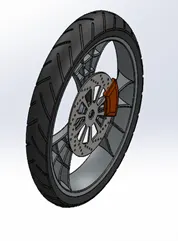
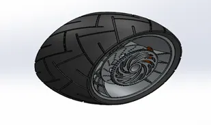
Front Wheel and Rear Wheel: Wheels are circular part attached to the rim. In this case front wheel smaller than the rear wheel. Both wheels include brake pads and caliper. Rear wheel only attached chain sprocket. Use the tools and features are extrude, extrude cut, revolve, revolve cut, chamfer, mirror, etc. First the rim and hub made by using revolve and other aesthetic features. Then the webbing of rim is done after makes caliper, sprocket.
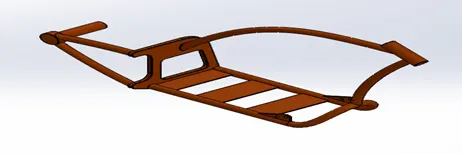
Chassis: Chassis is a mainly model using curve. Used for the tools and feature such as sweep boss, plane, curve, mirror etc. Project curve used to make front and back side tubes model. All tubes are created then the bottom plates are extruded from one tube to another tube. Then pedal is made using offset extrude. After all this done fillet, chamfer, mirror etc
Engine: This part start with the gear housing and stater motor housing. This housing is made with use of basic sketch tool and extrude features. The cylinder is made of polygon shape and cuts. The cylinder is then mirrored. After the mirror is done the pipes are connected cylinder with sweep features. Then exhaust is made by using projected curve and sweep features. 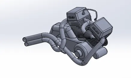
Gas Tank: The start of modelling is from the basic shape of gas tank which is created using surface sweep and other tools. Then the end of gas tank bend in triangular shape is made using projected curves and surface loft. The side surface is created using projected curve and surface loft. Then the seat is created by extruding. Then the bottom surface is created and closed tank is made. The fillet is avoid sharp curves. Then appearance is used it
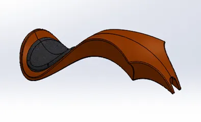
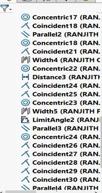
Assembly: Assembly is done by all the created components assemble space. First selected the chassis in assemble space and fixed it. Once the chassis is fixed using the mate options such as coincident, parallel to assemble all part components. After go to rendering factors.
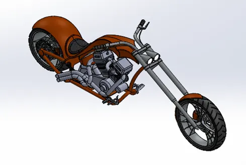
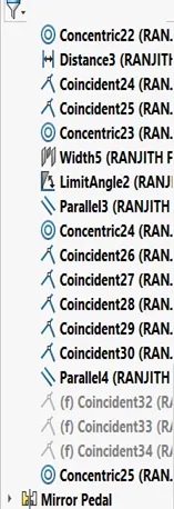
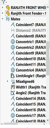
Render: Select the options in tool bar such as tools>add in> photo view in 360.Rendering is make realistic object so adding the scenes, deals, lights Etc. At last check the scene and proper light setup to make chopper realistic in final rendering.
CONCLUSION:
In this project,each part is designed individually and then given required and suitable apperance.Then all parts are assembled to create a model of American chapper with
renders to get realistic look.