Week 9:- 2D Detailing Challenge
Q.1) what are the Drawing templates?
Ans:
Drawing templates are the files of frames and title block which convey the design information that are used to generate 2 D drawing from 3 D part.
Neat and detailed Drawing templates convey more information from designer to manufacturer. so we can avoid misunderstanding and make a very effective
parts, which saves time and money.
Drawing templates are change as par the company standards
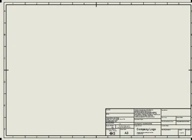
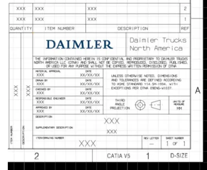
Drawing templates has n number of information such as:
1. Company name
2. Project Name
3. Sheet size
4. Sheet number
5. Angle of projection
Q.2) What do you understand by angle of projection?
Ans:
1. - Angle of projection
The angle at which an observer draw an object to convert it from 3D to 2D plane such as real object image to a plane paper is known as angle of
projection. 1st angle of projection(first quadrant of coordinate plane)
3rd angle of projection(3rd quadrant of coordinate plane)
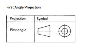
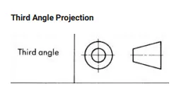
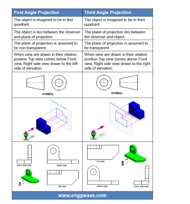
Differences between the First angle projection and third angle of projection:
1) In first angle projection object lies in the first quadrant while in third angle of projection, object lies in the third quardant.
2) In first angle projection, the top view comes on the bottom and the bottom view comes on the top of the front view while in third angle projection the top
view comes on the top of front view and the bottom view on the bottom.
Q.3) What is the First angle & Third angle projection? and why can't we use the 2nd and 4th angle of projection?
First angle of projection is a type of orthographic projection in which the object lies between the observer and the plane of projection. In this projection, the top view comes onthe bottom and the bottom view comes on the top of the front view. Similarly, the left view of the object is projected on the right and right view projected on the left. It is most commonly used in Europe and Asia region. Drawing templates contain the symbol of the type of projection to be used to project the images.
the view from the front is in the middle
the view from the left is on the right
the view from the right is on the left
the view from the top is on the bottom
the view from the bottom is on the top
the view from the rear is on the far right.
Third angle of projection is a type of orthographic projection in which plane of projection lies between object and observer. In this, the top view comes on the top of front view and the bottom view on the bottom. Similartly, left view is projected on the left and right on the right side of front view.It is used mostly in USA and Australia
the view from the front is in the middle
the view from the left is on the left
the view from the right is on the right
the view from the top is on the top
the view from the bottom is on the bottom
the view from the rear is on the far right.
Q.4) What is GD&T? What are the benefits of GD&T?
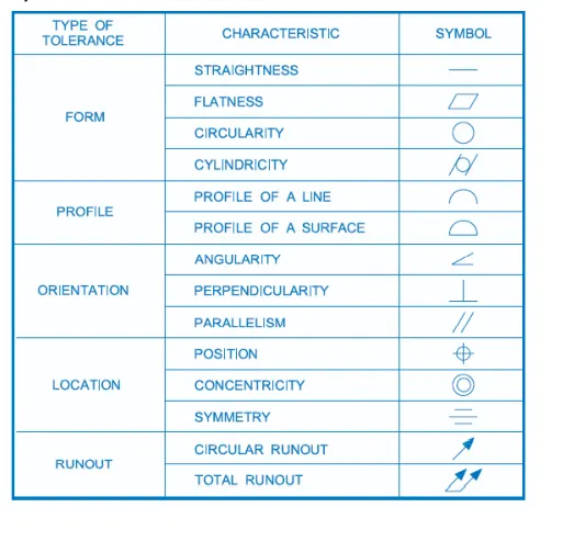
Symbols of GD&T come to mind first when we talk about GD&T. GD&T is not just about symbols. GD&T is the abbreviated form of Geometric Dimensioning and tolerancing. It is a system of defining and communicating engineering tolernces. It uses symbols to describe the nominal value and to what variation can it be made. GD&T helps to covey to the operator as to how much precision and accuracy is required in a particular feature of a part. GD&T can add value and reduce cost at the same time through producibility. In GD&T, there are a total of 14 symbols each of which has a specific function.
Benefits of GD&T:
1) GD&T is a language of engineers which they use to convey the tolerances and feaures in an easy and precise way.
2) GD&T can increase quality, add value and at the same time reduce cost.
3) It enhances design accuracy.
4) It maintains uniformity in drawings and makes it possible for comple designs to be implemented using diffrent features.
Q.5) Explain all the symbols used in GD&T?
GD&T has 14 symbols out of which 10 are most commonly used features.
1) Flatness- In this feature, all the elements are supposed to be in the same plane. Flatness error is calculated by the difference in the highest and lowest points on the plane. You are trying making sure that any point along the surface does not go above or below the tolerance zone. This feature doesnt require any reference.
2) Straightness- In this feature, all the elements are supposed to be in straight line. It is used for a line to comunicate the variation allowed in a line, hence maintaining it straight. It doesnot require a datum. If it is to be used for a cylinder, it is given along with the diameter dimension. It controls each dimention separately.
3) Cylindricity- This feature ensures that the surface of cylinder is smooth and within the tolerance zone. Each surface is at a fixed distance from the axis of cylinder in this feature. It does not require a datum.
4) Circularity- Circularity requires no datum. Circularity ensures all the points to be equidistant from centre. Circularity error is the radial distance between coaxial diameters. it limits the circularity error.
5) Perpendicularity- When this feature is applied to a surface, the tolerance zone is between two parallel surfaces perpendicular to the datum surface. It requires a datum surface.
6) Parallelism-When this feature is applied to a surface, the tolerance zone is between two parallel surfaces parallel to the datum surface. It basically ensures that all the points on referenced surface lies in the tolerance zone at a certain distance away from the datum surface.
7) Angularity- Angularity is a feature that is specified between two lines. It requires a datum reference from which the anglular tolerance is maintained. In case of a plane, angularity feature maintains the angular tolerance between two planes.
8) Position- Position tolerance shows the exact location of a FOS(feature of size) with respect to a datum. It tells us how far feature location can vary from its true position. It requires datum for reference.
9) Profile of a surface- Profile of a line is usually used at a place where we require a surface to be in the tolerance range. In this case, the profile directly mimics the design of the surface. Every point of the surface should fall within the tolerance zone.9) Profile of a surface- Profile of a line is usually used at a place where we require a surface to be in the tolerance range. In this case, the profile directly mimics the design of the surface. Every point of the surface should fall within the tolerance zone.
10) Profile of Line- This feature is used at places where a curve is to be maintained within the tolerance zone. The tolerance zone is two parallel curves from the main curve. It is used for advanced curves.
11)) Concentricity- Concentricity feature ensures the smoothness of a cylindrical surface with respect to a datum surface. A surface is chosen as a datum. The axis about which this surface is acts as a datum axis for the feature we wish to control.