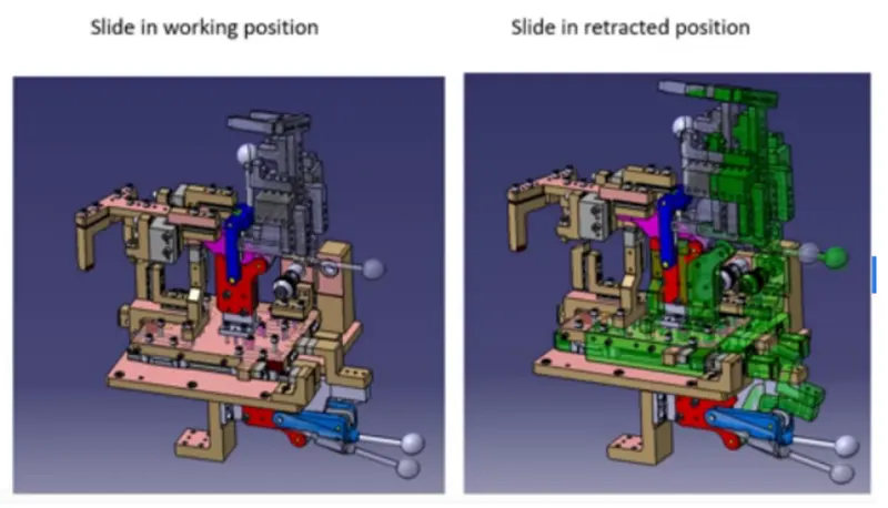
Week 3:- BiW Fixture Design Methodologies Challenges
1)What is Design Methodology?
Answer-Design methodologies is one of the pre design process which is the steps followed during the concept designing phases in fixture design.
- Purchase order.
- Inputs from customer.
- Percentage of completion criteria.
- Design outputs.
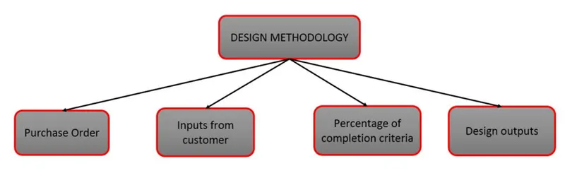
- Purchase Offer - On submitting our offer (Technical and Commercial), Customer gives a confirmation to start the design work.
- Inputs from customer are as follows:-
Functional requirements: The purpose or the function of the fixture will be given as inputs from the customers like what are the process the fixture is going to do e.g welding,gluing,riveting or whether it is a checking fixture,etc.
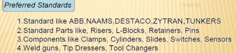
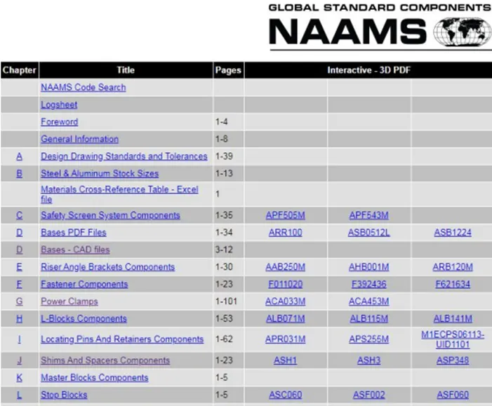
Preferred standards: As we know different companies follow different standards, we will be following the standards followed by the customers.
Car products: The inputs we get from car products are GD&T, part list, Cad files of car part, clamp plan, Product assembly process sheet.
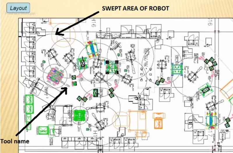
Layout: Layout shows the entire assembly plan to understand the process. Layout provides the information of flow of parts, station pitch, robot stations
Ergo Data: The inputs of Ergo data will given by the customer mostly in case of manually operated fixtures/manual fixtures. The Ergo data is mainly used to make the operator comfortable which may leads to improve the efficiency in cycle time & production. Ergo data provides inputs like Platform height, maximum & minimum reach from operator to fixture, maximum & minimum height of the fixture, whether the child parts/ assemblies are visible while clamping or loading & unloading.
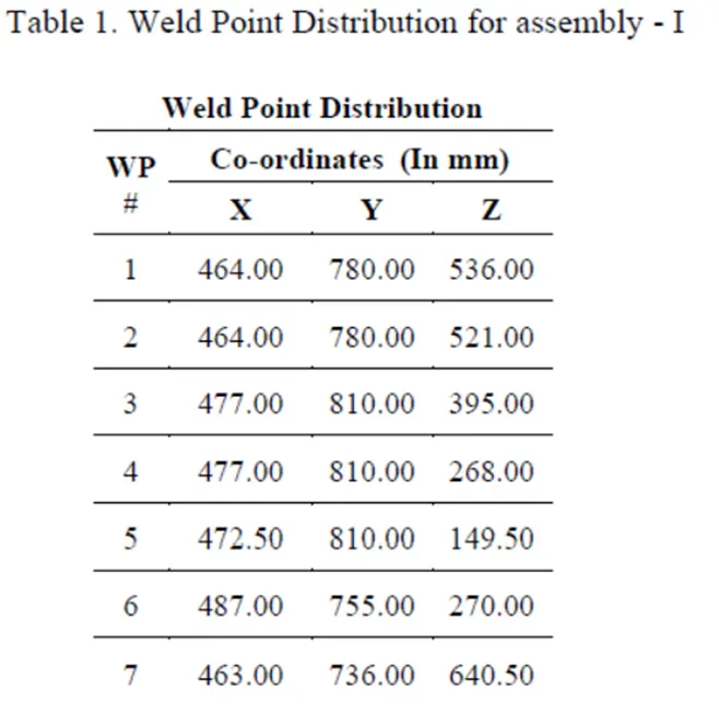
Weld study: It gives details about the study of particular gun that we use for welding. Also the datas like No. of weld, position of weld in the components will be given.
Templates: This inputs include the detailing templates of 2D cad drawing as per the customer standards.
Percentage completion- Percentage completion gives us an idea as to how much work has been completed. It is important to track the progress of the project so that it can be completed within the promised time to the customer.
- 0-25%- Input and Concept Design
- 25-40% - Concept Approval and Simulation Check
- 40-85%- Design freezing and detailing
- 85-100%- Check and final dispatch
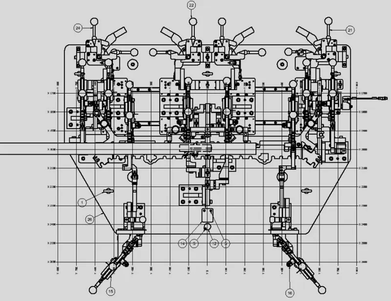
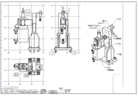
Design output: The output is 3D models & the 2D drawings of the tools. Which includes keysheets & layout sheets for unitized tool whereas no need of keysheets for non unitized tool.
2)What are the inputs required from the customer to start designing a Fixture?
Answer-
The inputs required from the customer to start designing a fixture are as follows,
- Functional requirements.
- Preferred standard components.
- Car products.
- Layout.
- Ergo - data.
- Weld study.
- Standard detailing templates.
1.Functional Requirements: The purpose or the function of the fixture will be given as inputs from the customers like what are the process the fixture is going to do i.e welding(Spot or seam weld),gluing,riveting,hemming or whether it is a checking fixture or a storage racks etc. It is one of the basic requirements to get from the customer to start designing a fixture.
2. Preferred standard components:
3.Car Products:
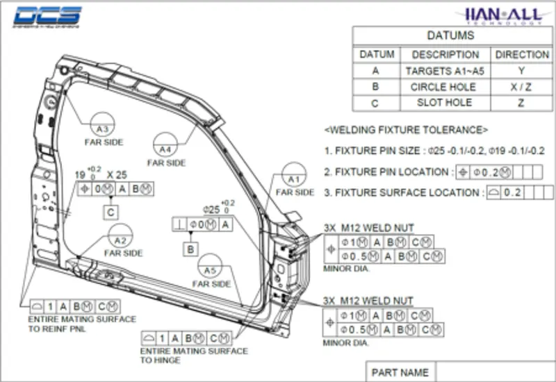
- GD&T: It provides information of locating pins, Rest, clamp, Damp & slide unit informaton of each station. Also includes the information of sequence of openings of clamps, dumps & slide stroke information.
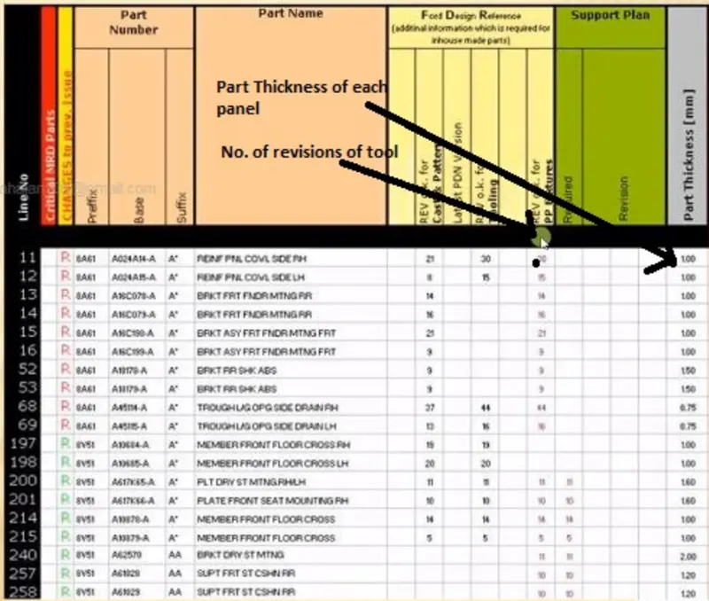
- Part lists: It gives the lists of parts which are going to assembled in the fixture. The list contains the informtion of Part number, part name, Revision of fixture, part thickness, etc.
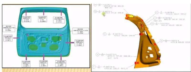
- Clamp plan: Clamp plan provides the informtion of location of pins, Rest units, clamp unit, Dumps etc. It is the important input from customer. The clamp plan/position should not be changed without the knowledge of customers.
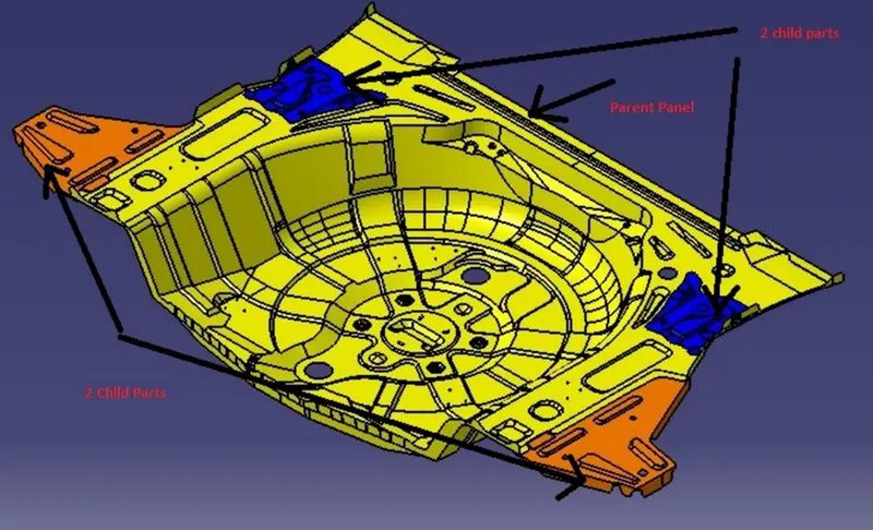
- 3D Cad file: The 3D model of the car part will be given from customer. From that 3D model we will be developing our fixture design process. The 3D cad file will be in the format of Step file (stp.) or IGES file ( igs.)
- Product assembly process sheet: It gives the information of stage wise assembly process like how the parts move from one assembly station to other after the completion of joining process.
4.Layouts: Layout shows the entire assembly plan to understand the process. Layout provides the information of flow of parts, station pitch, robot stations, Accessories like tool changers & tip dressers,sub assembly links, plat form height, loading/unloading sequence/height.
5.Ergo Data: - The inputs of Ergo data will given by the customer mostly in case of manually operated fixtures/manual fixtures. The Ergo data is mainly used to make the operator comfortable which may leads to improve the efficiency in cycle time & production.Ergo data provides inputs like Platform height, maximum & minimum reach from operator to fixture, maximum & minimum height of the fixture.
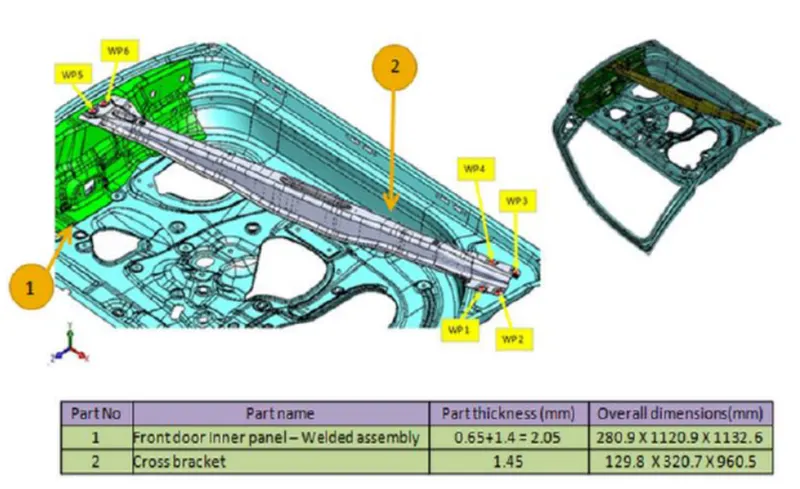
6.Weld Study: Weld study is the important inputs given by the customer.It gives details about the study of particular gun that we use for welding. Also the datas like No. of weld, position of weld in the components will be given
7.Standard Detailing Templates - Every customer have their standard of detailing & the templates which are used for 2D drawing & detailing.
3)What is the input we get from "Car Products"?
Answer-
- GD&T: The geometric dimensioning and tolerencing which is an important part of designing is provided for the part for which fixture must be designed. It provides the information of location of the pins, rest, clamp, dump & slide of each station. The clamp opening sequences dumps & slide stroke.
- Part list contains all the panels that are being welded in the assembly
- CAD Files:The 3D model file of the car part is given from the customer to study on it.The car part is designed by using 3D modelling software.From this we can get some conceptual idea of the designing of fixture. The model is going to be the base of the fixture design
- Clamp plan: Clamp plan provides the informtion of location of pins, Rest units, clamp unit, Dumps etc. It is the important input from customer. The clamp plan/position should not be changed without the knowledge of customers. It gives the detail of the exact position of the clamping units.
- Layout provides the following information:
Flow of parts- It shows how one part after an operation moves to another station.
Station Pitch- Distance betwen two stations
Robot Staions- Shows where robots are placed
Accesories like tool changer and tip dresser- With the help of Tool changers, robots can perform multiple operations like gluing and transporting the panel.
Sub assembly links- It shows how the sub assembly stations are linked to main assembly.
Platform Height- It tells height of platform
Loading/unloading Sequence- It shows loading and unloading sequence of panels, like where to unload the panel and where to load it next.
4)What is the Clamp plan?
Answer-
Clamp plan: Clamp plan provides the informtion of location of pins, Rest units, clamp unit, Dumps etc. It is the important input from customer. The clamp plan/position should not be changed without the knowledge of customers. It gives the detail of the exact position of the clamping units.
5)What is the purpose of a Layout?
Answer-Layout provides the following information:
Flow of parts- It shows how one part after an operation moves to another station.
Station Pitch- Distance betwen two stations
Robot Staions- Shows where robots are placed
Accesories like tool changer and tip dresser- With the help of Tool changers, robots can perform multiple operations like gluing and transporting the panel.
Sub assembly links- It shows how the sub assembly stations are linked to main assembly.
Platform Height- It tells height of platform
Loading/unloading Sequence- It shows loading and unloading sequence of panels, like where to unload the panel and where to load it next.
6)What is Ergo data?
Answer-
Ergo Data: The inputs of Ergo data will given by the customer mostly in case of manually operated fixtures/manual fixtures. The Ergo data is mainly used to make the operator comfortable which may leads to improve the efficiency in cycle time & production. Ergo data provides inputs like Platform height, maximum & minimum reach from operator to fixture, maximum & minimum height of the fixture, whether the child parts/ assemblies are visible while clamping or loading & unloading.
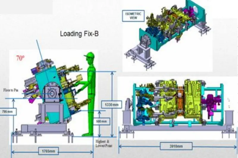
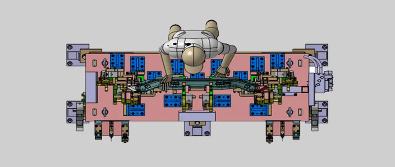
Benifits of Ergonomics:
- Improved working condition.
- Reduce physical workload.
- Improved work postures.
- Reduced efforts of certain movements.
- Better reading instrument displays, handling of machine levers & controls.
- Reduced unnecessary information recall efforts.
7)What do you understand by Weld study?
Answer-
Weld study is the important inputs given by the customer.It gives details about the study of particular gun that we use for welding. Also the datas like No. of weld, position of weld in the components will be given.
- Geo weld points: The Geo weld points are which is planned in the Geo fixture. These weld will determine the postion of the panels as per the given data in drawing. The Geo weld points are represent in red spheres in the weld study inputs given by the customers.
- Respot weld points: The Respot weld points are planned in the Respot tool. These weld will determine the strength/stiffness of the panel/components. The Respot weld points are represent in green spheres in the weld study inputs given by the customers.
8)What are the criteria for percentage completion in the designing stage? Explain it in detail.
Answer-
Percentage completion- Percentage completion gives us an idea as to how much work has been completed. It is important to track the progress of the project so that it can be completed within the promised time to the customer.
- 0-25%- Input and Concept Design
This phase of design involves starting of design by studying the GD&T, clamp plan, weld study, layout, assembly process and making a concept design based on these inputs based on 321 principle. Then we manually put the guns at weld points to check fowling with other units. It is then sent to the customer.
- 25-40% - Concept Approval and Simulation Check
On customer approval, we give the concept design for simulation check. Simulation checks the gun accesibility and the path clearance for gun.
- 40-85%- Design freezing and detailing
Next, Design is freezed and final finishing is performed and as the design is freezed, detailing is performed on the freezed design units. On its completion, we can say that the project is 85% complete.
- 85-100%- Check and final dispatch
Finally, the design is QC checked and dispatched. This is the final task to be performed.
9)Brief about "Output" in design?
Answer-
Design output: The output is 3D models & the 2D drawings of the tools. Which includes keysheets & layout sheets for unitized tool whereas no need of keysheets for non unitized tool.
A Design Output is a drawing or specification or manufacturing instruction. Design Outputs describe all the components, parts, and pieces that go into your medical device. Design Outputs describe all assemblies and sub-assemblies of your product.
-
key sheet- It shows the index of the unit & their placement on tool base.
- Layout sheet- It is the detailed drawing individual unit to include all their components.
10)What do you understand by structuring a design tree? How does it reduce errors during the design process?
Answer-
It is an important process which helps us to identify a specific part or assembly as to which project, tool or unit, it belongs to.This helps us to avoid the errors during design study, manufacturing, assembly, inspection etc.If the parts or assemblies are not properly or the design tree is not structures properly, it will create confusion to understand the design & may create major possibilities of making an error.
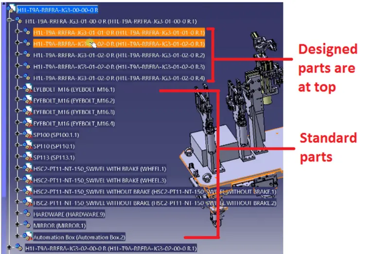
The blue highlighted number is
H1L-T9A-RRFRA-JG3-00-00-00
H1L-T9A-The project name
RRFRA-Panel name
JG3- Jig no. 3
00-Unit no.
00-part no.
00-Component no.
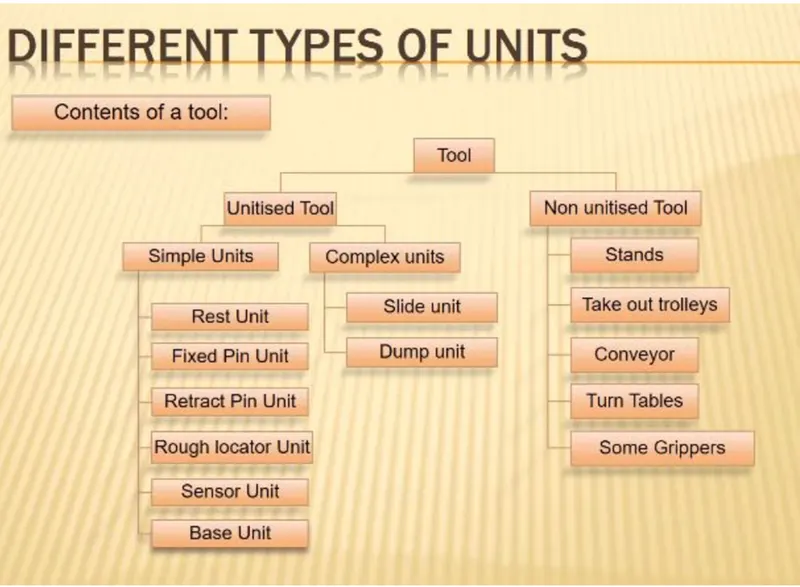
11)What are Units? Mention 5 types of units.
Answer-
UNIT:A unit is a device that has a specified function, especially one forming part of a complex mechanism.
The BIW fixtures is the assembly of different units which are designed to fulfill different purpose.The unit have the specified function like resting the panel,
clamping the part, Locating the part etc.
12)Describe Fixed Pin units & their purpose?
Answer-
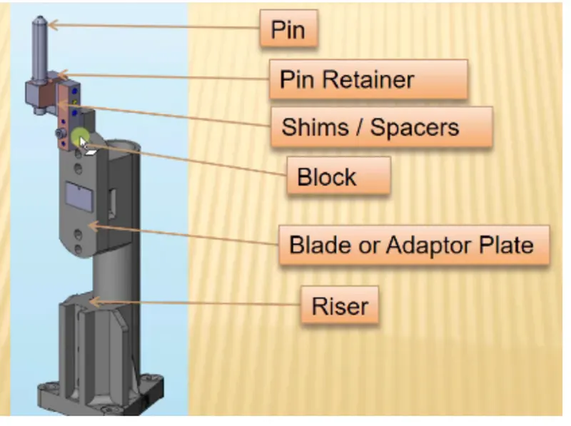
Fixed Pin Unit-A fixed unit is a unit designed to locate the car panels using pins.The fixed pin unit is the part of the 3-2-1 principle. It restricts 6 degrees of freedom of the car panel.It is necessary to have 2 pins to locate car panel. one pin must arrest 4 way (4 translational ) & other must arrest 2 way (2 rotational ) of a car panel.
13)What are the different parts of a fixed unit?
Answer-
- Riser- Riser is the standard part which is used to rise up the height of the while unit
- Blades - These are plates mounted on the riser. Other parts like cylinder, arms etc are mounted on the blade.
- Shims- These are the small part which comes with the thickness of 0.1mm, 0.2mm, 0.5mm etc.
- Pin retainer - It will support the pin.
- Locating Pin- Typically, locating pins are used for controlled, fine tolerance positioning of a work piece.
14)What is the purpose of making a Rest unit & describe its parts?
Answer-
The rest units are designed to rest/support the car panel by using NC blocks/Mylar/Rest.
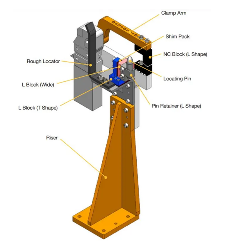
- 1) Riser- Riser is the standard part which is used to rise up the height of the while unit
- 2)Blades - These are plates mounted on the riser. Other parts like cylinder, arms etc are mounted on the blade.
- 3)Shims- These are the small part which comes with the thickness of 0.1mm, 0.2mm, 0.5mm etc. These will compensate the stackup tolerance which reflects at the panel holding part called Mylars. We give tolerance to all the parts of the fixture.
- 4)Pin retainer - It will support the pin.
- Locating Pin- Typically, locating pins are used for controlled, fine tolerance positioning of a work piece.
15)What are the basic fundamentals to design a Sensor unit?
Answer-
Every single loose panel which are being welded in a tool should be sensed,hence we sensor units. Sensor is a device which detects or measures a physical property and records, indicates, or otherwise responds to it.A unit designed to sense car panel using electrical sensors is called sensor unit. The from the sensors is send to the PLC so the next process is executed by this signal.
There are different types of sensors
a)Proximity sensor
b)Laser sensor
c)Photo electric sensor
d)Infrared sensor etc.
16)What is a Rough locator unit & what are the basic fundamentals to consider while designing it?
Answer-
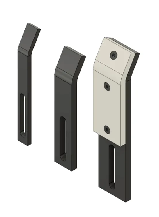
The rough locators are used to guide the operator how to locate the car panel on to the pins accordingly. The rough locater can be a standard or make part. It guides in loading and unloading the panel.
The fundamentals followed while designing a rough locator unit-
- The rough locator should be placed at the edges of the panel so that the panel is guided.
- It should be placed as the same angle of the car panel edge with minimum distance of 2 to 5 mm from the edge of the panel.
- In general it is designed to guide the panel in pin arresting direction and it also should be in angle parallel to panel edge.
- The rough locator should be guiding the panel before 10-15mm of the pin engagement.
17)What is a Base unit and describe it's parts?
Answer-
A Base unit is the unit designed to mount all the other units(Clamp unit, Pin unit, rest unit etc.) of the tool, also other parts necessary for a tool like pneumatic valve box, trunking cable path will also be mounted on to a base unit.
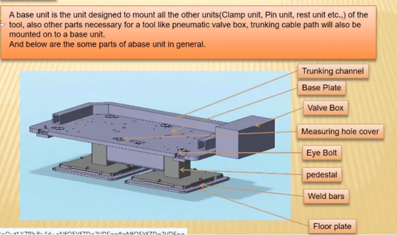
Floor plate- It is the plate which join the fixture to the floor by using some nut bolts. This plate surface is machined for maintaining the horizontal position of the fixture.
Weld bars & pedestal- Pedestal is the base or support on which a the fixture is mounted.
Eyebolt- An eye bolt is a bolt with a loop at one end. They are used to firmly attach a securing eye to a structure, so that ropes or cables may then be tied to it.
Measuring hole cover -The measuring hole is drilled over the base plate which having exact cordinates so that all other holes can take reference from it. The measuring hole no. depends on the size of base plate. These holes are covered by using some plate to protect against dust, damage etc
Base plate- Base plate is the heavy plate of large thickness becuase it carries all the weight of the mounted parts.
18)What is a Dump Unit and what are its functions?
Answer-
When we have some geometrical constraints then we can not mount normal units like clamp unit, pin unit etc. In this case the dump unit is used.
- Dump unit is the complex unit to design due to space constains there is less space avilable & have to adjust all the parts in available space
- It consist of dump cylinder to perform the operation of clamping & unclamping car panel.
19)What is a Slide unit? Mention where Slide units are commonly used.
Answer-
Slide units are positioning units which are used to position the fixture, weld gun,units,robots into position for further operations.Slide units can be classified into two types on the base of the type of guide-ways used as-
- Hardened guide ways
- LM guide way
Slide units can be calssified into three types on the base of the prime mover used-
- Manual slides
- Hydraulic/pneumatic slides
- CNC slides
It may also be classified depending on application as-
- Horizontal slide
- Vertical slide
- Angular slide