Week 9:- 2D Detailing Challenge
Q.1)
DRAWING TEMPLATES:
Drawing templets are the files of frames and title block which convey the design information that are used to generate 2D drawing from 3D part.
Neat and detailed drawing templets convey more informationfrom designer to manufactuar.So we can avoid misunderstanding and make a very effictive parts,which saves time and money.
Drawing templets are change as per the company standards.
Drawing templets are provided by the customer at the starting of the project ,If not then we should finalize at starting of project.
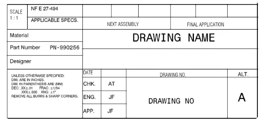
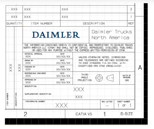
Drawing templets has 'n' nuber of informations such as:
- Company name.
- Project Name.
- Sheet Size.
- Sheet Number.
- Angle of Projection.
- Revision number/letter(if its revision drawing).
- Signature or name of drawn by,checked by,responsible engineer and approved by.
- Parts detail.
- Quantity.
- Additional notes(surface finish,Heat treatment,Material detail,etc.)
- Scale,Date,Unit of measurement.
*Note:Above standards can vary as per comany standards.
Q.2)
- Technical drawing usually consists of various 2 dimentional views to define an object,This is known as orthogonal projectiom methods used internationally are first angle projections and third angle projection.
- If some detailed of view can be inferred from another then you don't bother to draw that view.
- The angle at which an observer draw an object to convert it form 3D to 2D plane such asreal object image to a plane is known as angle of projection.
- It's way of showing a 3D object on a 2D piece of paper and it shows what a part looks like each direction-top,bottom,left and right.
Accroding to the rule of orthographic projection,to draw a projection view of a 3D object on 2D plane.Horizontal plane is rotated in the clockwise direction.
Orthographic Representation
Orthographic projections are 3D representation of 2D objects.Features of 3D parts are presented on flat plane,as through the outline of part had been projected onto a screen
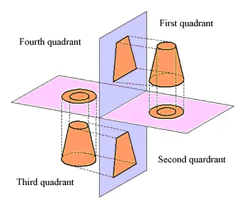
The viewing angles are split into quardinates of first angle,second angle ,third angle and forth angle.
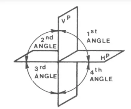
in particularly only first angle and third angle quadrent are used since these are pure views the second angle and forth angle quadrant are combimation of first and third angle projection and cause confusion to the reader.
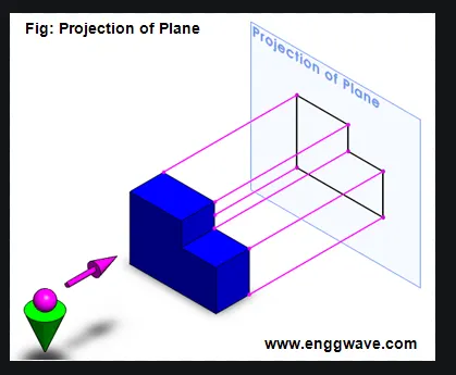
The principle of first angle projection is shown below:
Here the views looks at the 3D shape and projects the image onto a screen behind the component.
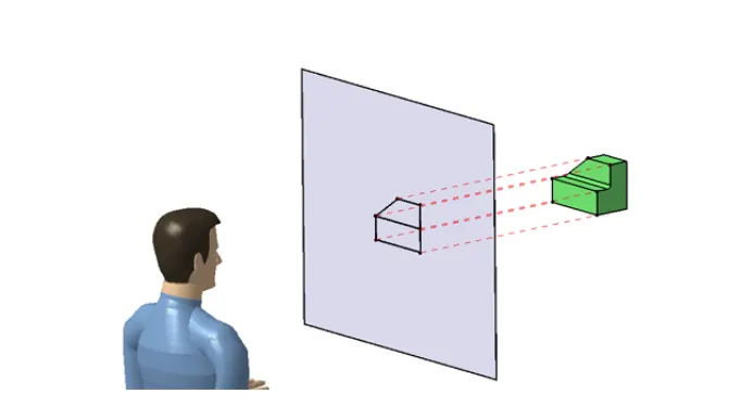
The principle of third angle projection is shown blow:
Here the viewer looks at the 3D shape and projects the image onto a screen in front of the component.
Q.3)
FIRST ANGLE PROJECTION:
In the first angle projection system,objects are placed in the first quadrant.And it lies between the observer and the plane of projection.
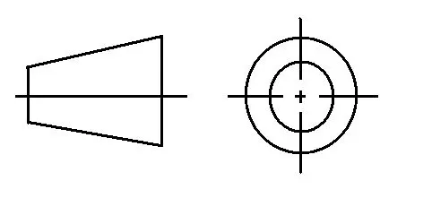
SYMBOL:
Below fig: shows the view in 1st angle of projection:
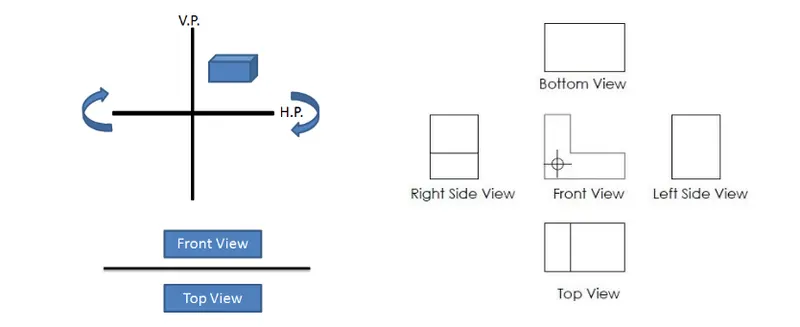
Front view and top view in first angle of projection:
To draw front and top views,object front and top views are projected on vertical and horizontal plane respectively.
Accroding to the rule of projection,the Horizontal plane is rotated in the clockwise direction.Horizontal plane rotation brings top viewin the bottom of projected front view.
Right and left hand view in first angle of projection:
To draw right and left side views are projected on vertical left and vertical right plane respectively.
To bring the right side view on 2D plane,Rule of orthographic projection is used.Left plane unfolded towards the left side.Therefore right side view is projected on the left side of the front view.
Whereas the left side view is projected on the right side of the front view.
THIRD ANGLE OF PROJECTION:
In the 3rd angle projection,objects are placed in the third quadrant and projection lane lies in between observer and the object.
SYMBOL:
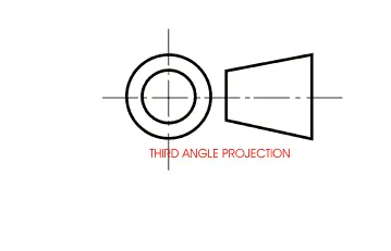
Below fig: shows the view in 3rd angle of projection:
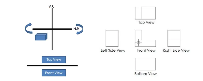
Front and top view in 3rd angle of projection:
To draw front and top views in 3rd angle projection.Object front and top views are projected on vertical and horizontal planes respectively.
As per rule of projection,The horizontal plane is rotated in the clockwise direction.THis rotation brings top view on top of projected front view.
Right and left sid view in 3D angle of projection:
Object Right and left side views are projected on vertical right and vertical left planes respectively.
To draw the right side view on 2D plane,Right plane is unfolded toward the right side.As a result right side view is projected on the Right side of front view.
Similarly,The left side view is projected on the left side of the front view.
Bottom view is projected on the bottom plane and placed on bottom of front view.
Why 2nd and 4th angle projection is not use?
Second and forth angle projection system has some limitations.Therefore only 1st and 3rd angle projection system are used to prepare engineering drawings.
To understand why 2nd and 4th angle projection are not used,Firstly we need to understand the behind the orthographic projection system.
How projection system works:-
Let's consider a point in A and B in 1st and 3rd quadrant respectively.As per rule of projection,to bring drawing views from three dimensional to two dimenstional planes.Horizontal plane(HP) is rotated in clockwise direction.
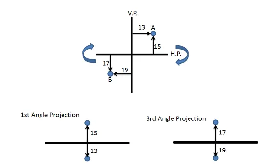
As Shown,PointA in 1st quadrant lies in between observer and projection plane.Therefore front view of pont A will be in vertical plane(VP) and top view will be on horizontal plane.
To understand why the 2nd and 4th angle projection system are not used.We will repeat the above experiment in second and forth quadrant.
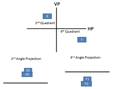
Let's consider rectangular parts X and Y are placed in 2nd and 4th quadrant respectively.
In the second quadrant,Vertical plane lies in between object X and observer.Therefore front view of object X will lie on vertical plane.As per rule of projection when horizontal plane is rotated 90 degrees in clockwise direction,Top and front view will overlap.
Overlapping projection views create confusion in the drawing.Therefore second angle projection is not used.
Similarly when the object is placed in 4th quadrant both top and front view will overlap.Therfore 4th angle projection is also not used.
Q.4)
GEOMETRIC DIMENSIONING AND TOLERANCING (DS&T):
GD&T is design is design approch and manufacturing mechanism that helps engineers and designers comunicate how to bring a part design to life.When documented correctly using GD&T ,it is possible to build a part that exactly matches its on-paper plans.
The drawing is a controlling document that ensures the vendor is creating precisely what the customer's design requires.Mechanist and quality engineers will use GD&T , print dimensions and drawing notes to develop a manufacturing process and inspection methodology that will construct high precision components matching the designer's original version.Proper print detailing will also help with measurement correlation to aid in the communication between customer and vendor.
GD&T uses a symbolic language to indicate how significantly part features can deviate from the geometies listed in the design model.THis language contains all the relevent details involved in fabrication,including dimensions,tolerances,definisions,Rules and symbols that comunicate a component's functional requrements.These all currently follow ASME Y14.5M-2009(previsously ASME Y14.5M-1994).
Engineers and designers look GD&T to design critical aspects of a part features,including a specific features desired location,form,profile and orientation.It is common practice to use the profile destination tied to the datum structure that is related back to the solid CAD model.This allows manufacturing to use a best fit protocol.
Five major Advantages:
GD&T,a vital part of complex machining,offers a number of major advantages:
- Saving money- GD&T enhances design accuracy by allowing for appropriate tolerances that minimize production.For many projects,The process provides extra or bonus tolerances,further increasing cost effectivenes.
- Ensuring Dimentional and tolerance Requirements-By explicity stating all design requirements,a through GD&T process gurantees acurate fulfillment of all dimensional and tolerance specifiactions.
- Assising Digital Design Methods-Clear,concise GD&T data is readily adaptable to digital design programs,including nearly universally used 2D and 3D CAD files.
- Offering uniformity and Convenience-As a single consistant language GD&T reduces guesswork and interpretation while ensuring consistant geometries across design and manufacturing.
- Providing Accurate Communication-Today's intricate design demand the most accurate and reliable communication.GD&T enables designers manufactures,inspectors to comunicate clearly with one other,saving time and making the process more efficient.
Q.5)
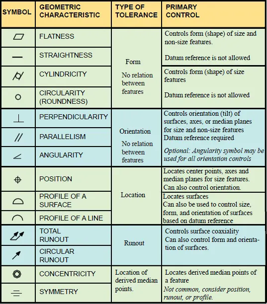
There are a total of fourteen GD&T characteristics,and the symbols that represent them are shown below:
Form Tolerances controls the 'shpae' of features and are often used as a refinement of size.
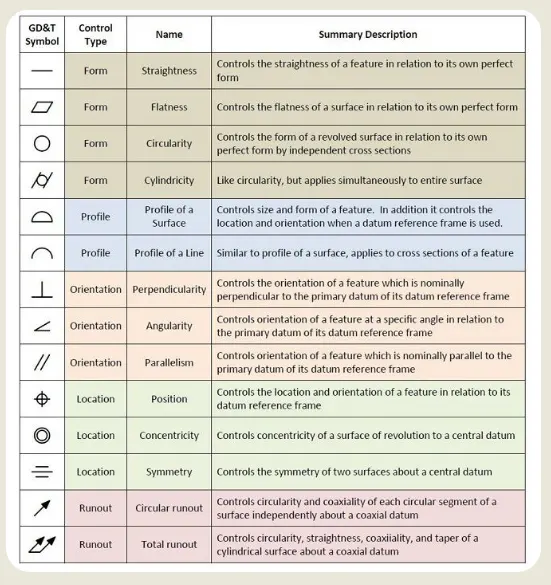
Orientation Tolerances control the "tilt"of feature and are always associated with basic angle dimensions,often used as a refinement to location applied to surfaces,orientation tolerances also control form.
Location Tolerancea control location and are always associated with basic linear dimensions.Position locates and orients the median plane or axsis of features of size.Profile locates feature surfaces.Profile is the most powerfull cheracteristics of all and also controls orientation and form.
Runout is howmuch one given reference feature or feature vary with respect to another datum when the part is rotated 360 deg. around the datum axsis.It is essentially control a circular feature and how much variation it has with the rotational axsis.Runout can be called out on any feature that is rotated about the axsis.It is essentially how much "wobble"occurs in the one part feature when referenced to another.
Some other symboles used in GD&T:
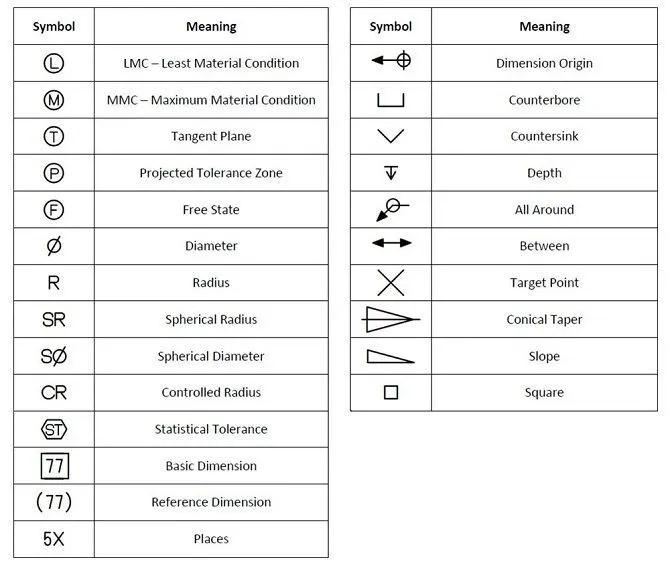
Least material condition(LMC):The condition where the feature contains the least material within the stated limits of size(eg.small pin or large hole).
Maximum material condition(MMC):The condition where the feature contains maximum material with in the stated limits of size(eg.large pin /small hole).
Projected tolerance zone:The projected tolerance zone applies to a feature's protrusion.In most cases the zone to which geometric tolerances applied is limited to the range of feature specified in the drawing.In contrast to this,indications using the projected tolerance zone can specify a virtual zone for the specified features mating part.
Basic dimensions:Basic dimensions are theoretically exact numerical values used to define form,size,orientation,or location of part or feature.Basic dimensions are usually shown on a drawing enclosed in a box,but they can also be invoked by referencing a standard or by anote on the drawing.
Free state:Adds the free state modifier,to indicate that the geometric tolerances applies in the unrestrained condition.This modifier is only appicable for not rigit parts for which there is a note that indicates that tolerances are specified for the restrained state.