Week 9:- 2D Detailing Challenge
Q.1)What are the Drawing templates?
Ans:
Drawing templates are the files of frames and title block which convey the design information that are used to generate 2D drawing from 3D part.
Neat and detailed drawing templete convey more information from designer to manufacturing . so we can avoid misunderstanding and make a very effective parts , which saves times and money.
Drawing templete are changes as per company standards.
Drawing templates are provide by the customer at the starting project, if not then we should finalize at starting of project.
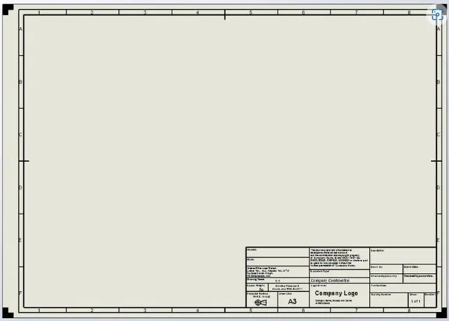
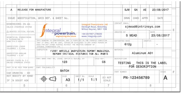
Drawing templates has n number of information such as:
1.Company Name
2.Project Name
3.Sheet number
4.Sheet size
5.Angle of projection.
6.Revision number / latter (if revision drawing )
7.Signature or name of drawn by , checked by , resposible engineer and approved by
8.Parts detail
9.quantity
10.Additional notes (surface finish , heat treatment , material details , etc)
11.Scale , date, unit of measurement
*Note : Above points can as per company standards
Q.2)What do you understand by angle of projection?
Ans:
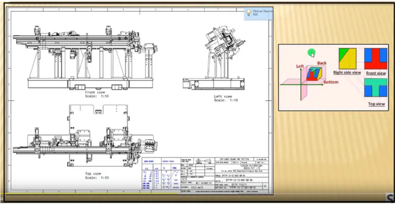
1.Technical drawing usually connsist of various two dimensions views to define an object this known as orthogonal projection , the two orthogonal projection method used internationally are first angle third angle projection.
2.If some detailed of view can be inferred from another , then you don't bother to draw that view.
3.The angle at which an observe draw an object to convert it from 3D to 2D Plane such as real object image to a plane is known as angle of projection.
4.It's way of showing a 3D object an a 3D objects on a 2D piece of paper, and it shows what a part looks like each direction -top, bottom , left and right.
According to the rule of orthographic projection . to draw a projection view of a 3D Object on 3d plane . horizontal plane is rotated in the clockwise direction.
Orthographic Representation
Orthographic projection are 3D representation of 2D objects.feature of 3d parts are presented on flat plane , as through the outline of part had been projectd onto a screen.fig illustrate. fig illustrate the principle.
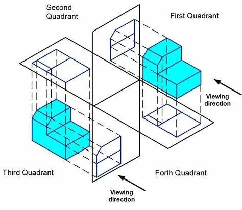
the viewing angles are split into quadrants of first angle , second angle third angle and fourth angle.
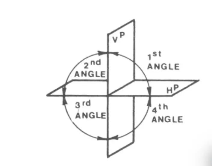
In practically only first angle quadrant and the third angle quadrant are used since these are pure views , the second angle quadrant and fourth angle quadrant are combination of first and third angle projection and cause confusion to the reader.
the principle of first angle projection is shown fig. here the viewer looks at the 3D shape and projected the image onto a screen behind the component .
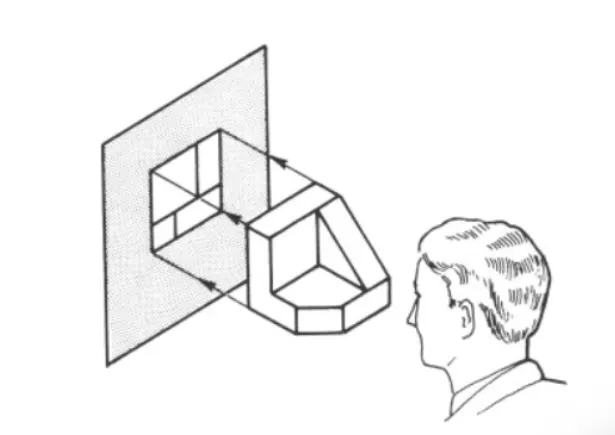
3.What is the first Angle & Third angle projection?and why can't we use the 2nd and 4th angle of projection?
Answer:
First angle of projection:-
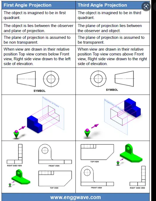
In this , the object is assumed to be positioned in the first quadrant & is shown in figure . The object is assumed to be positioned in between the projection planes & the observer . the views are obtained by projecting the images on the respective planes.
In this type of projection , the objects is imagined to be in the first quadrant becouse the observer normally looks from the right side of the quadrant to obtain the front view , the objects will come in between the observer and the plane of projection . therefore , in this case , the object is imagined to be transparent, and the projector are imagined to be extended from various points of the object to meet the plane they from an images , thus in the first angle projection , any view is so plasced that it reprensent the in the side of the object away from it .
- The basic different between first & third angle of projection are as belows.
- Why 2nd and 4th angle projection is not used?
second & fourth angle of projection syatem are not used to draw engineering drawing becouse of the limitaion of overlapping projection views.
How Orthogonal projection system works?
let's consider a point A & B in the 1st and 3rd quardrant repectively . As per rules of orthographic projection , to bring drawing views from three dimensional to two dimansions planes. Horizontal planes(HP) is rotated in the clockwise direction.
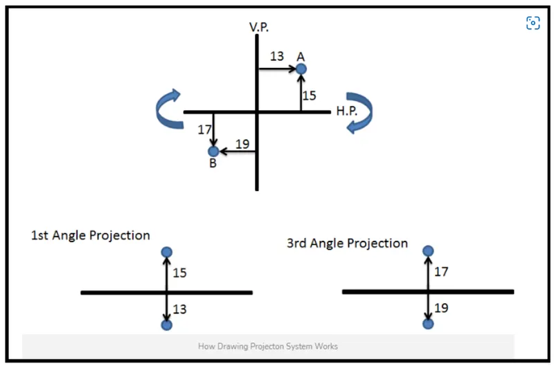
As shown in the above image, point A in the 1st quadrant lies in between the observer and projection planes. therefore front view of point A will be the vertical planes (V.P) and the top view will be on the horizontal & vertical plane.
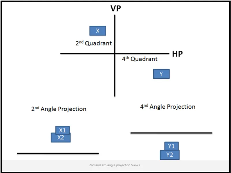
To understand why the 2nd & 4th angle orthogonal projection system are not used to draw engineering drawing . we will repeat the above experiment of creating engineering drawing views in the second & fourth quadrant.
lets considred rectangular parts X & Y are placed in 2nd & 4th quadrant respectively.
In the second quadrant , the verticle plane (vp) lies in between ojects X & observer .
Therefore the front view of objects x will lie in vertical planes whereas top view will on horizontal plane. as per rule of projection when the horizontal planes rotated 90 degree in clockwise direction , top & front view will overlap. Overlapping projection views creat confusion in the drawing . therefore the 2nd angle projection system is not used to draw engineering drawings. similarly drawings. similarly . when the object is placed in the 4th quadrant both top & frint view will overlap . therefore fourth angle projection is also quaddrant both top & front view will overlap. therefore fourth angle projection is also not used.
4.What is GD&T? What are the benefits of GD&T?
Answer:
Geometric dimesions and tolerance (GD & T) is a system for defining and communication engineering tolerences.
It uses a symbolic language on engineering drawing and computer -generated and communication engineering tolerances.
it uses a symbolic language on engineering drawing - generated three - dimensional solid models that explicitly describe nominal geometric and its allowable variation.
It tells the manufacturing staff and machines what degree of accurancy and precisions needed on each controlled featured of the part.
GD & T is used to defines the nominal (theoretically perfect) geometry of parts and assemblies , to defines the allowable variation in from and possible size of individual features , and to defines the allowable variation between faetures.
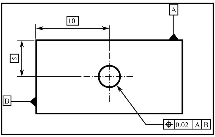
Dimensions specification defines the nominal as- modeled or as -intended geometry. one example is a basic dimensions. Tolerance specification defines the allowable variation for the from and possible the size of individual featured , and the allowable variation in orientation and location between features. two example are linear dimensions featured control frame using a datum reference (both shown above)
GD & T: Is a method (system of symbols) for defining a part's geometry
-it goes beyond the from description
-Based simply on tolerance dimensions
A featured control frame (the backbone of GD&T) modifies a part geometry
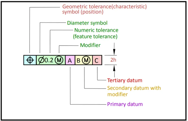
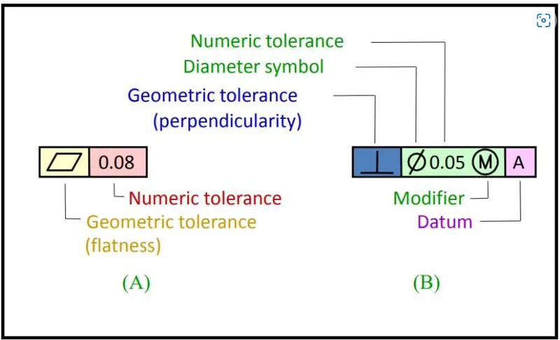
Two additional example of featured control frame modifying a part's geometry.
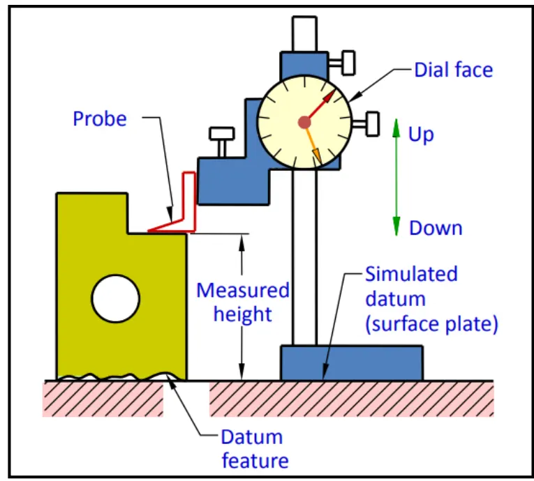
A datum is exact surface , line, point, axis or cylender from which measurement taken.
-Ex. A surface plate or a polished slab of granite (simulated datum)
-3 points define a plane.
-Datum featured - is the surface of the part in contact with the simulated datum
A height gage measures the height of an object from the simulatd datum surface plate.
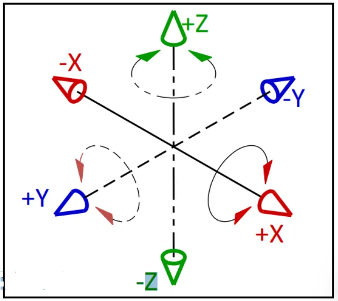
Degrees of freedom (12)allow movement in two direction along each axis and rotation about each axis(clockwise and counterclockwise)
In order to measure geometric features . part motion must be restricted . A datum reference frame consists of three intersecting planes at 90 degrees to each other.
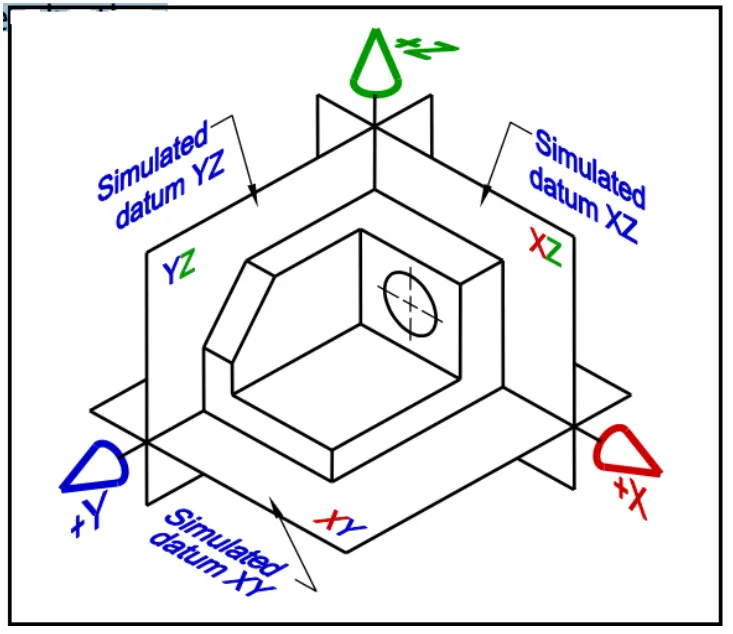
The part can still move in the positive x ,y & z direction " part motion must be restricted"
What if we temporaily clamped the part?-Mearurement can be taken from the simulated datums.
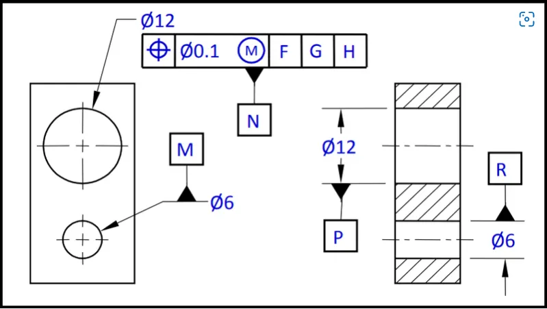
The datum symbol is applied to solid cylinders.
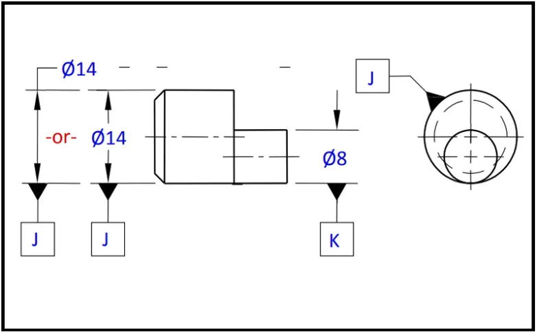
The datum symbols is applied to holes.
Order of datum : primary s has 3 parts of contact , secondary datum T has 2 pts and tertiary U has has 1st of contact
the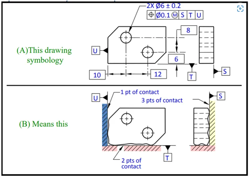
There are several standared available worldwide that describe the symbols and defines the rules used in GD&T . One standard is american society of mechanical engineer (ASME)Y14.5.
Benifits of GD & T :-
A)Saving Money:-GD&T enhance design accurancy by allowing for appropriate tolerance that maximize production , for many projects , the process , the process provide extra or bonus tolerance , further increasing cost effectiveness.
Ensuring Dimensional and tolerance requirements:-By explicity stating all design requirements.a through GD&T process guarantees accurate fulfillment of all dimensional and tolerance and specifications.
c)Assisting Digital Design Method - Clear , concise GD & T data is readily adaptable to digital guesswork and interpretation while ensuring consistent geometries across design and manufacturing.
e)Providing accurate communication-Today's intricate design demand the most accurate and rekiable communication . GD&T enables designers, manufacturer and inspector to communicate clearly with one other . saving time and making the process more efficient .
5.Explain all the symbols used in GD&T?
Ans:
There are a total of fourteen GD&T Characteristics , and the symbols that represent them are shown below
GD&T Symbols Reference
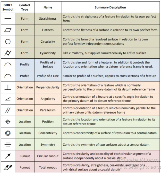
From tolerance control the "shape" of features and are often used as a reifinement of size
Orientation tolerance control the tilt of feature and are always associated with basic angle dimension . after used as a refinement to location . if applied to surfaces, orientation tolerance also control form
Location Tolerance control location and always assocciated with basic linear dimension position locator and orients the median plane or axis of feature of size profile locates feature surfaces. profile is most powerful characteristic of all and also controls orientation and form.
Least Material condition(LMC):-The condition where the feature contains the least material with in the stated limits of size (ex: smallest pin and/or largest hole)
Maximum Material condition(MMC):-The conditions where the feature contains the maximum material with the stated limits of size (ex: largest pin and o/ or smallest hole)
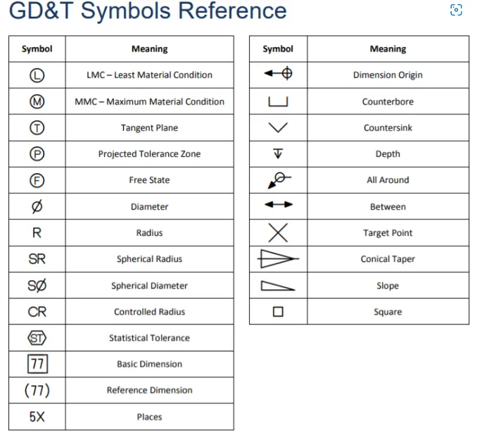
Projected Tolerance zone:-The projected tolerances zone applies to a feature's protrusion in most case the zone to which geometric tolerances is applied is limited to the range of the feature specificed in the drawing . in the drawing . In contrast to this , indication using the projected tolerance zone can specify a virtual zone for the specified featurcing a standard or by a note on the drawing.