Week 9:- 2D Detailing Challenge
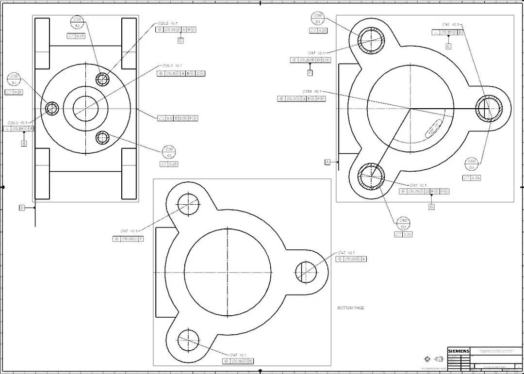
- What are the drawing templates?
Drawing templates are the files of frames and title blocks which convey the design information that are used to generate 2D drawing from the 3D part.
Neat and detailed drawing templates convey more information from designer to manufacturer. So we can avoid misunderstanding and make very effective parts which saves time and money. Drawing templates change as per the company standards. Drawing templates are provided by the customer at the starting of the project, if not then we should finalise at the starting of the project.
Drawing templates have N number of information such as:
- Company name
- Project Name
- Sheet size
- Sheet number
- Angle of projection
- Revision Number/latter(if its revision drawing)
- Signature or name are drawn by, checked by, responsible engineer and approved.
- Parts detail
- Quantity
- Additional notes(surface finish, heat treatment, material detail, etc)
- Scale date, unit of measurement.
-
- What do you understand by angle of projection?
-
Angles of projection:
- The angle at which an observer draws an object to convert from 3D to 2D plane such as real object image to a plane paper is known as angle of projection.
- Angles of projection are basically the view formats for orthogonal views of assemblies or parts.
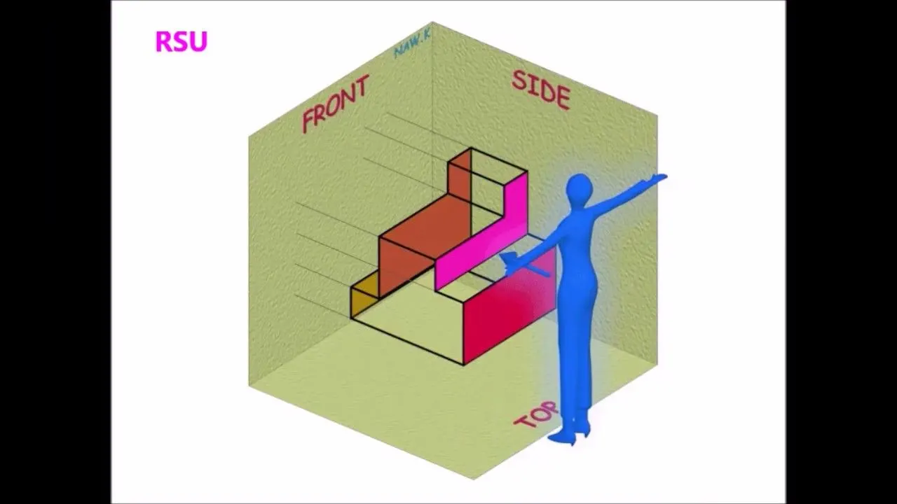
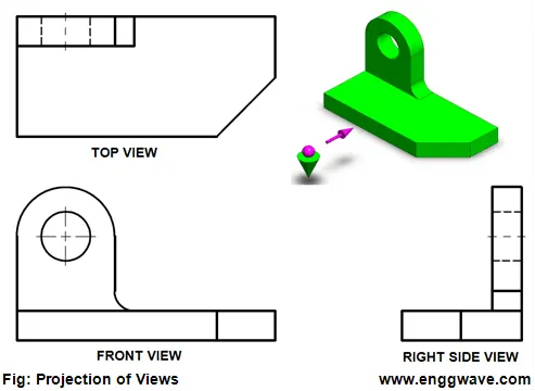
- Orthographic projections : It is a technical drawing in which different views of an object are projected on different reference planes observing perpendicular to respective reference planes.
- Different reference planes are horizontal plane, vertical plane, vertical frontal plane , side or profile plane.
- Different views are front view, top view and side view.
- Front view is a view projected on VP
- TV is a view projected on HP
- Side view is a view projected on PP.
- What is first angle and third angle projection? And why can't we use the 2nd angle and 4th angle projection?
First angle of projection:
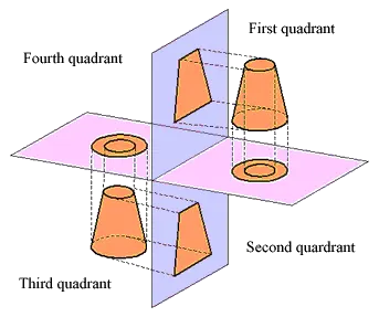
- In this, the object is assumed to be positioned in the first quadrant and is shown in the figure. The object is assumed to be positioned in between the projection planes and the observer. The views are obtained by projecting the images on the respective planes.
- In this type of projection the object is imagined to be in the first quadrant. Because the observer normally looks from the right side of the quadrant. Because the observer normally looks from the right side of the quadrant to obtain the front view, the objects will come in between the observer and the plane of projection. Therefore, in this case the object is imagined to be transparent, and the projectors are imagined to be extended from various points of the object to meet the projection plane.
- When these meeting points are joined in order on the plane they form an image, thus in the first angle of projection any view is so placed that it represents the side of the object away from it.
Third angle projection:
- Here the object is assumed to be in the third quadrant that is the object behind the vertical plane and below the horizontal plane. In this projection technique, placing the object in the third quadrant puts the projection planes between the viewer and the object shown in the figure.
- In this type of projection, the object is imagined to be in the third quadrant. Again as the observer is normally supposed to look from the right side of the quadrant to obtain the front view, in this method , the projection plane comes in between the observer and the object. Therefore the plane of projection is assumed to be transparent. The intersection of this plane with the projectors from all the points of the object would form an image on the transparent plane.
Why is the 2nd and 4th angle projection not used?
Second and fourth angles of projection systems are not used to draw engineering drawings
because of the limitation of overlapping projection views.
How does an orthographic projection system work?
Let's consider points A and B in the 1st and 3rd quadrant respectively. As per rule of orthographic projection, to bring drawing views from three dimensional to 2 dimensional planes. Horizontal plane is rotated in the clockwise direction.
As shown in the above image, point A in the 1st quadrant lies in between the observer and projection plane. Therefore the front view of point A will be in the VP and top view will be on the HP. Similarly point B in the 3rd quadrant can be projected on the horizontal and vertical plane.
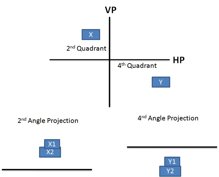
To understand why the 2nd and 4th angle orthographic projection systems are not used to draw engineering drawings. We will repeat the above experiment of creating engineering drawing views in the second and fourth quadrant.
- What is GD and T? What are the benefits of GD and T?
- Geometric Dimensioning and tolerancing is a system for defining and communicating engineering tolerances.
- It uses a symbolic language on engineering drawings and computer generated three dimensional solid models that explicitly describe nominal geometry and its allowable variation.
- It tells the manufacturing staff and machines what degree and precisions needed on each controlled feature of the part.
- GD and T is used to define the nominal geometry of parts and assemblies, to define the allowable variation in form and possible size of individual features and to define the allowable variation between features.
- Dimensioning specifications define the nominal as modelled or as intended geometry. One example is the basic dimension. Tolerancing specifications define the allowable variation for the form and possibly the size of individual features and the allowable variation in orientation and location between features.
- GD&T is a method for defining a parts geometry.
Benefits of GD and T:
- Saving money
- Ensuring dimensional and tolerance requirements
- Assisting digital design methods
- Offering uniformity and convenience
- Providing accurate communication
Explain all symbols of GD&T.
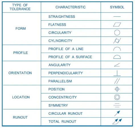
The table above shows different symbols used in GD and T. In form tolerance we have straightness which indicates the straightness part of the surfaces. Flatness indicates the flatness of the surfaces of the parts, similarly the circularity and cylindricity indicates the holes.
In the profile tolerance the profile of the line or the surface are indicated by semi arc and semicircle respectively.In the orientation tolerances the angular , perpendicular and parallel orientations are defined.In the location tolerances the position concentricity and symmetry of the parts are indicated in runout tolerances the circular run out which is given at a particular place or portion of the part where as total run out is given to the whole part.