Week 1:- Introduction to BiW and Fixtures Challenge
1) What is BIW and define its parts?
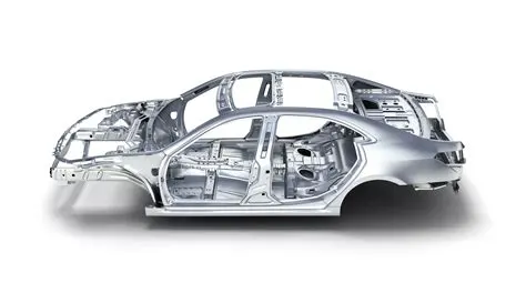
BIW- The expansion of the abbrevation BIW is Body in White. The outer skeleton of the car body which is not yet painted is called body in white. The sheetmetal body after joining together by different joining processes is dipped in primer which is grey in colour. Because of this colour the car skeleton is known as body in WHITE. Body in Grey doesnt sound good. It is a stage in automobile manufacturing in which a car's sheet metal body frame has been joined together, thats is before painting and before the chasis, engine, trim(glass, door, lock handles, seats, electronics) have been integrated into the structure. The assembly involves different techniques such as welding,riveting and lazer brazing.
BIW parts are classified as follows:
- Underbody structure
- Body side structure
- front end structure
- Closure
- Roof
1) Underbody structure:
- Engine compartment( Front end under frame)
- Main floor
- Rear end under frame( Rear compartment)
2) Body side structure:
- Body side outer
- Body side inner
3) Closures:
- Hood
- Back door
- front door
- Deck lid
4) Roof:
- Roof inner
- Roof outer
5) Fender
2) What do you understand by BIW nomenclature?
BIW nomenclature refers to naming or identification given to BIW components of a car body.
3) What is Fixture and its types?
A device which holds the work piece to be processed, that means to be welded, glued, rivetted etc.
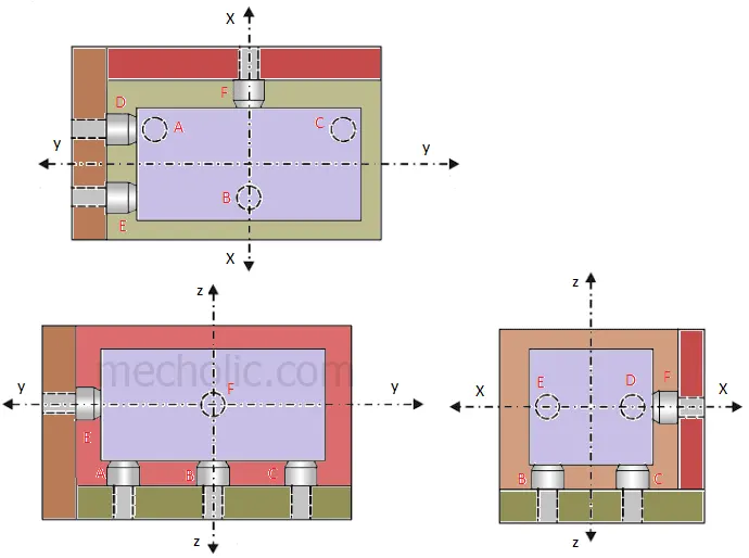
3-2-1 priciple is used in designing a fixture.
A fixture is a work-holding or support device used in the manufacturing industry. Fixtures are used to securely locate (position in a specific location or orientation) and support the work, ensuring that all parts produced using the fixture will maintain conformity and interchangeability. Using a fixture improves the economy of production by allowing smooth operation and quick transition from part to part, reducing the requirement for skilled labor by simplifying how work pieces are mounted, and increasing conformity across a production run.
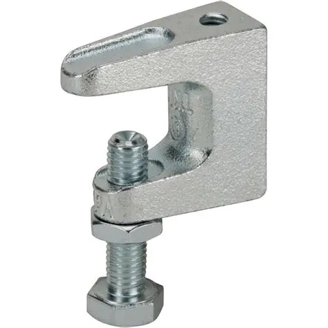
A clamp is a fastening device used to hold or secure objects tightly together to prevent movement or separation through the application of inward pressure.
Types of fixtures:
- Production fixtures:These fixtures are used during mass production.Before manufacturing all the erors in the results are noted for the initial batch based on which the fixture is modified to minimize the errors and produce an error free part.
- Pre-production fixtures: These fixtures are used for the initial batch to study the feasibility.
- Checking fixtures:These fixtures are used for car panel geometric inspection purpose.
4) What is the basic principle of fixture design?
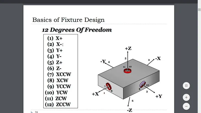
The basic design of a fixture is to arrest the degrees of freedom of the work part.
There are 12 degrees of freedom in total. They are:
Translational: X+,X-, Y+, Y-, Z+, Z-
Rotational: Xcw, Xccw, Ycw,Yccw,Zcw,Zccw.
- 1. Meet the stability and reliability of workpiece positioning during use;
- 2. Have enough bearing or clamping force to ensure the machining process of the workpiece on the tooling fixture;
- 3. Meet the simple and fast operation in the clamping process;
- 4. The vulnerable parts must be of a structure that can be replaced quickly. When the conditions are sufficient, it is best not to use other tools;
- 5. Meet the reliability of repeated positioning of fixture in the process of adjustment or replacement;
- 6. Avoid complex structure and high cost as much as possible;
- 7. Select standard parts as component parts as far as possible;
- 8. Form the systematization and standardization of the company’s internal products.
A good machine tool fixture must meet the following basic requirements:
- 1. To ensure the machining accuracy of the workpiece, the key to ensuring the machining accuracy is to correctly select the positioning datum, positioning method and positioning elements. If necessary, it is also necessary to analyze the positioning error, and pay attention to the influence of the structure of other parts in the fixture on the machining accuracy, so as to ensure that the fixture can meet the machining accuracy requirements of the workpiece.
- 2. To improve the production efficiency, the complexity of the special fixture shall adapt to the production capacity, and various fast and efficient clamping mechanisms shall be adopted as far as possible to ensure convenient operation, shorten the auxiliary time and improve the production efficiency.
- 3. The structure of the special fixture with good process performance shall be simple and reasonable to facilitate manufacturing, assembly, adjustment, inspection and maintenance.
- 4. With good performance, the fixture shall have sufficient strength and stiffness, and the operation shall be simple, labor-saving, safe and reliable. On the premise of objective conditions and economic applicability, pneumatic, hydraulic and other mechanized clamping devices shall be used as far as possible to reduce the labor intensity of the operator. The tooling fixture shall also be convenient for chip removal. If necessary, a chip removal structure can be set to prevent chips from damaging the positioning of the workpiece and damaging the tool, and prevent the accumulation of chips from bringing a lot of heat and causing the deformation of the process system.
- 5. The special fixture with good economy shall adopt standard components and standard structure as far as possible, and strive to have simple structure and easy manufacturing, so as to reduce the manufacturing cost of the fixture. Therefore, the necessary technical and economic analysis of the fixture scheme should be carried out according to the order and production capacity, so as to improve the economic benefits of the fixture in production.
5):
Types of BIW stations:
BIW assembly line comprises of the following:
- Tools:Geo tool, re-spot tool, marriage tool and framer tool
- Grippers- Material handling grippers, Process Grippers, Combo gripper, Dual Gripper
- Stands- pedestal stand, glueing stand, docking stand.
- Miscellaneous- Curing, Buffer, racks, conveyors.
Tools:
Geo Tool:
Tool where part geometry is defined and it ensures that geometry is not distorted in and after the welding process.
The pin tolerance for geo pin is -0.15mm.
Re-spot tool:
Fixture in which the remaining weld spots are welded which are not achieved in geo tool.
The pin tolerance is-0.28mm
Marriage tool:
This tool is also called a hemming tool which joins the inner panel and outer panel.
Framer tool:
Roof members are added to the marriage tool outcome.
Grippers: A fixture which holds the car panel and is fixed to the manipulating end of the robot. Gripper tool is called EOAT( End of arm tooling). They are frame based structures which are light in weight.
Material handling gripper: Grippers which handle car panels from one station to another.
Process handling gripper:These grippers aid in pedestal welding, glueing, sealing etc.
Combo grippers: A combination of gripper and weld gun.
Dual gripper: It is for handling car panels from one station to another with two sided grippers.
Stands:
Glueing and sealer stand: Glueing gun or sealing gun fixed to standard welded stand grounded to the floor.
Docking stand: When robots are selected for multi-tasking like material handling and welding , which cannot carry out both due to limitations due to some limitations, the robot will drop a gripper or gun after completing the respective operation with the help of a docking stand.
6):
Mylars/Fingers: These elements are actuated by pneumatic or hydraulic clamps for ensuring proper clamping force. As these elements function close to the weld flame they are made of titanium nitrates or tungsten.
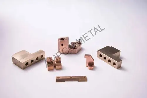
PLP: Primary locating points- this is a reference for maintaining all the other dimensions in a part.
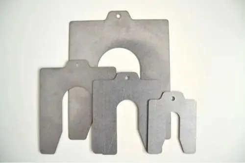
Shims: Addition of shims are used to adjust positions to rule out the error due to each individual tolerance stack ups.
Number plates/ name plates:Coordinate plates contain information on reference coordinates for calibration purpose.
Clamping unit: Sufficient clamping force should be used to keep the parts in place. Excessive force may result in buckling of the element.
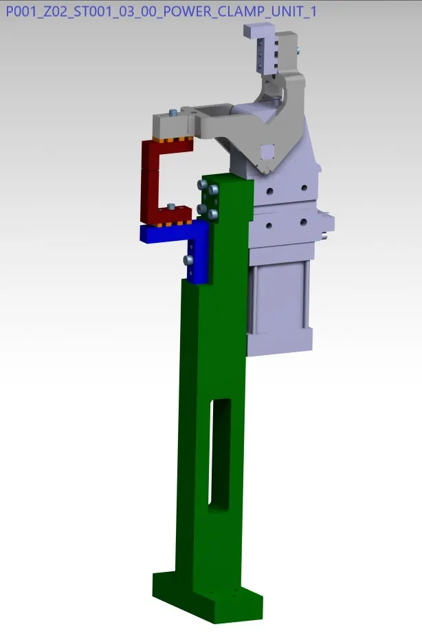
Pivot:Axis around which clamp rotates.
Class A surface: Surface of the car visible to the customer. The clamping of this surface should be done using soft material as no mark should be left.
Reed switches and Sensors: reed switches are electrical parts which confirm the piston position. If these devices are not working the whole assembly line stops.
Hardwares: Nuts and Bolts which are used are also called as hardware.