Week 2:- BiW Fixture Basics Challenge
1. What is the process of project execution activity?
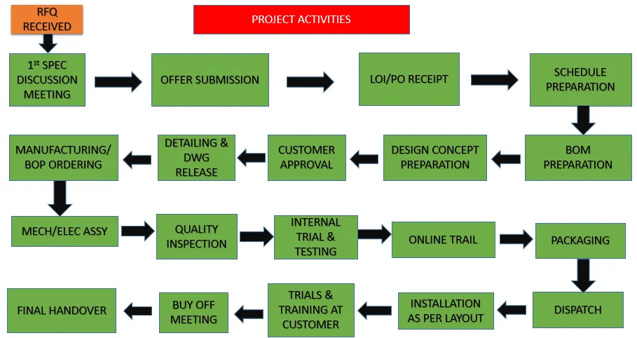
- RFQ: The full form of this abbreviation is Request for quotation. This is the first and foremost step in which the customer quotes his requirements, specifications, technical offer, commercial offer, expected timeline of the project and other details in the form of documents.
- 1st spec discussion meeting: After receiving the RFQ the discussion meeting will be carried out on technical offer,commercial offer, project execution , timeline required to complete the project and will be finalised. In this meeting the time required for all the steps from rough drawing to final manufacturing are considered and cost and time minimization will be given more priority in this discussion.
- Offer submission: The finalised results of the 1st spec meeting will be documented and submitted to the customer for review and feedback.
- LOI/PO: Letter of Intent or Purchase order is the document declaring the preliminary commitment of one party to do business with another. All the offer letters received by the customer will be received and the best suited will be approved and the purchase order will be sent.
- Schedule preparation: After receiving the PO the project schedule preparation will be done to meet the deadlines and to complete the project. All the steps in the project are taken into account like POreceipt, 1st spec design meeting, design date analysis, 3D design preparation and simulation etc.The time required to finish the individual activity is calculated and then the total time will be calculated to check whether the project can be finished in specified time or not. If it seems to be not possible alternative plans are also to be prepared. These alternative plans come into action in project completion whenever there are deviations.
- BOM preparation: Bill of the material is prepared for the project by considering each and every step.
- Design concept preparation: Based on the customer requirements and specifications the design of the project and details of the project are prepared in this step and sent for approval of the customer.
- Customer approval: In this step the customer reviews the design and checks whether the design fulfils the requirements or not according to the technical offer. If everything is good then the customer gives the approval otherwise suggestions and corrections will be sent on which we have to work on and again we have to send for approval. This goes until we get the final approval from the customer.
- Detailing and drawing release: After the customer approval detailed drawings and designs will be released . Like dimensions, quantity specifications etc.
- Manufacturing/BOP ordering: In this step the manufacturing process begins . All the required parts like motors, cylinders , sensors, grippers etc for manufacturing are ordered as per the design specifications.
- Mechanical/ electrical assembly: In this step all the parts received from BOP ordering will be analysed for quality check and then the mechanical and electrical assembly of the parts will be done.
- Quality inspection: After the assembly the assembled part will be done with quality checks. In this all the dimensions, positional accuracy, coordinates are checked by using a CMM machine. Once all the quality checks are passed then only it will be sent to the next step otherwise it will be sent back for obtaining a good assembly.
- Internal trial and testing: In this step, internal trails are done on the fixture to evaluate its operational feasibility. For this they perform various simulations and manual trials for the testing of fixtures.
- Online trial: It is done in the automated mode by using electrical connections. The process sequence is checked as per the defined way in design. This is done in front of the customer to take their approval as well.
- Packaging: The assemblies are packed in proper manner in such a way that no damage occurs during transportation. Otherwise a small damage will lead to distortion of the geometry of the fixture and also the functionality of the fixture. Hence the proper packaging is very important.
- Dispatching: Once the packaging is done the fixture will be dispatched to the customer address.
- Installation as per layout: Layout is the space defined for the parts like fixture, robots etc. The layout is designed by considering the functionality , application, sequence etc. Hence installation is to be done as per layout.
- Trials and training at customer: Production trials are performed at the customer end after the proper installation. In the technical offer we have specified the quality benchmarks. Trials are done to check and show the capability of the fixture to the customer.
- Buy off meeting: In this meeting we allow the customer to ask their doubts and also we provide additional information related to the project.
- Final handover: In this step the product is finally handed over to the customer.
2) What are the types of joining processes?
Joining processes involves joining two metal parts either temporarily or permanently with or without application of heat and pressure.
Joining can be done in two types
- Mechanical joining
- Metallurgical joining
Mechanical joining:It is a process of joining using mechanical methods which involves screws, nuts, rivets and bolts etc. The threaded holes employed for mechanical joining are vulnerable to fractures. In ductile materials, the fracture can come from fatigue. While in brittle materials the fracture can simply result from mechanical overloading. Thus mechanical joints must be designed with fatigue failure and brittle fracture in mind.
Metallurgical joining: It joins two metals involving metallurgical changes in it. Sometimes metals will be fused or heated or filler materials may be added etc. Welding , brazing, diffusion bonding, soldering adhesive bonding fall into this category.
- Welding: It is a joining process in which the work pieces are joined by melting/fusion. A common method for welding known as arc welding, consists of generating an electric arc between an electrode and the work pieces to be welded together. The arc generates enough heat to melt the electrode and the work pieces are welded together. The melted metal from the electrode and the molten base metal join together and form a solid joint. The gases generated while welding form a shield which stabilises the arc.
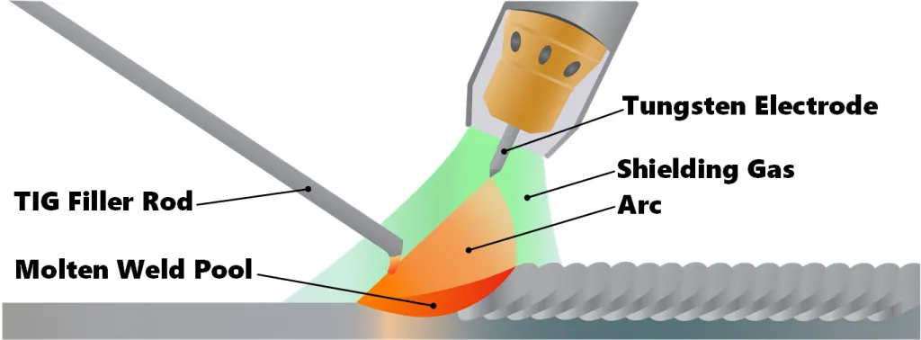
TIG: This process has become famous in welding metals like Magnesium and Aluminium. An arc is formed between a pointed tungsten electrode and the workpiece in an inert gas atmosphere, mostly helium or argon.
MIG: Metal inert gas welding is an arc welding process that uses a continuous solid wire electrode heated and fed into the weld pool from a welding gun. The two base materials are melted together forming a join.
Seam welding:Seam welding is the joining of work pieces made of similar or dissimilar materials along a continuous seam. Seam welding can be broken down into two main techniques, resistance seam welding and friction seam welding.
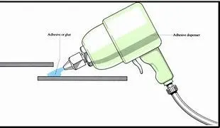
Adhesive Bonding: This type of joining uses adhesives which are chemicals to join the metals. Adhesive bonded joints can withstand shear, tensile and compressive stresses. To increase the bond strength surfaces to be joined by adhesives must be cleaned thoroughly which minimises the gap between the adhesive and the adherent. Rough surfaces also improves the bond because of the mechanical interlocking.
3) What is resistance welding and its application in the automotive sector?
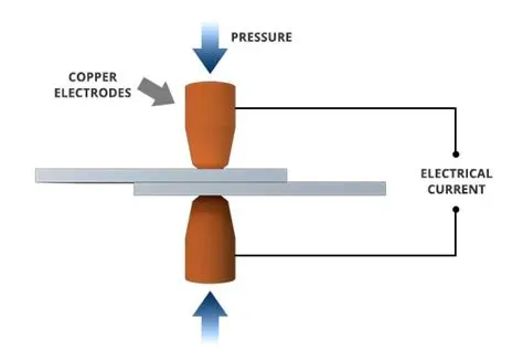
Resistance welding is a joining of metals by applying pressure and passage of current through the metal area to be joined. In this joining no extra material is required and it is also cost effective. Resistance welding are of different types such as spot welding, seam welding projection, flash welding. The electrodes used in this welding are copper based alloys. Resistance welding machines are designed and built for a range of automotive and industrial applications.
Resistance spot welding: Resistance spot welding is used widely in the automobile industry.It is used in joining the inner and outer parts of the BIW structure. First the weld spots are marked at regular intervals and the workpieces are placed in between the two electrodes. The required force and power supply will be given to spot weld.
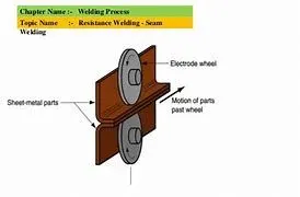
Resistance seam welding process: This process is used where leakage is to be avoided. In this kind of welding there will be rollers used. The materials to be welded are placed between the two rollers. An impulse is created between the two rollers and a spot weld is done when the two metals melt and join.
Resistance seam welding process: This process is used where leakage is to be avoided. In this kind of welding there will be rollers used. The materials to be welded are placed between the two rollers. An impulse is created between the two rollers and a spot weld is done when the two metals melt and join.
Resistance seam welding process: This process is used where leakage is to be avoided. In this kind of welding there will be rollers used. The materials to be welded are placed between the two rollers. An impulse is created between the two rollers and a spot weld is done when the two metals melt and join.
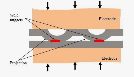
Resistance projection welding: Resistance projection welding is almost similar to resistance spot welding. The work piece with projections are joined. Since the only contact points between the workpiece are projections. The pressure and current flows pass through the projections and joining takes place at that region; such type of resistance welding is called resistance projection welding.
4) What is fusion welding and types of fusion welding with its application in the automotive sector?
Fusion welding process uses heat to join or fuse two or more materials by heating them to a melting point. The process may or may not require the use of a filler material. External application of pressure is not required for fusion welding processes, except for resistance welding, where substantial contact pressure is required during welding for sound joining.
The different types of fusion welding are:
- Shielded metal arc welding: It is also known as manual metal arc welding, flux shielded arc welding or stick welding that uses a consumable electrode covered with a flux to lay the weld. An electric current either AC or DC, is used as a welding power supply. The work piece and the electrode melts forming a molten metal pool that solidifies to form a joint. As the weld is laid the flux coating of the electrode gives off vapours that serve as shielding gas and providing a layer of slag both of which protect the weld area from atmospheric contamination.
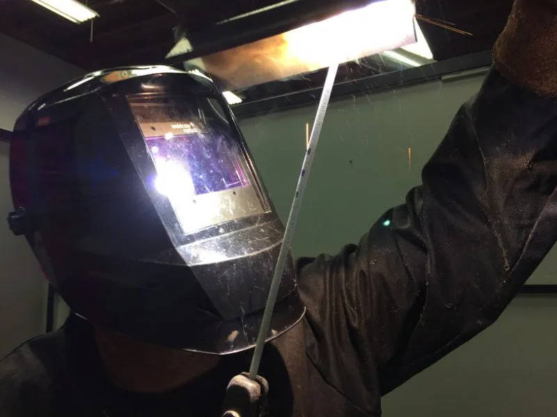
- Metal inert gas welding: Metal inert gas welding is an arc welding process that uses a continuous solid wire electrode heated and fed into the weld pool from a welding gun. The two base materials are melted together forming a join.
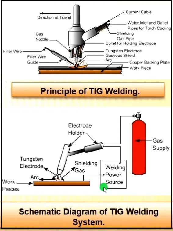
Tungsten inert gas welding: This process has become famous in welding metals like Magnesium and Aluminium. An arc is formed between a pointed tungsten electrode and the workpiece in an inert gas atmosphere, mostly helium or argon.
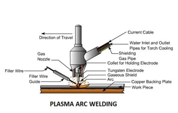
- Plasma arc welding: This process uses an electric arc created between an electrode and torch nozzle. The electric arc ionises the inert gas argon in the chamber creating what is called plasma. It is then forced through a fine bore copper nozzle that constricts the arc and directs it to the workpiece allowing the plasma arc to be separated from the shielding gas( mixture of argon and hydrogen).
5) What is the 3-2-1 principle?
During the metal working process, for example welding, the workpiece must be held properly in the correct position for exact weld to take place.Any variation of the part location on the fixture adds to dimensional tolerance that must be assigned to finished parts. The method of supporting and securing the part in the fixture affects not only dimensional tolerances, but surface finishing as well.Techniques for supporting and clamping must be considered together with the method of locating in order to assure repeatability from part to part. The basic principle of the fixture is to restrict all the degrees of freedom in the desired location and orientation.
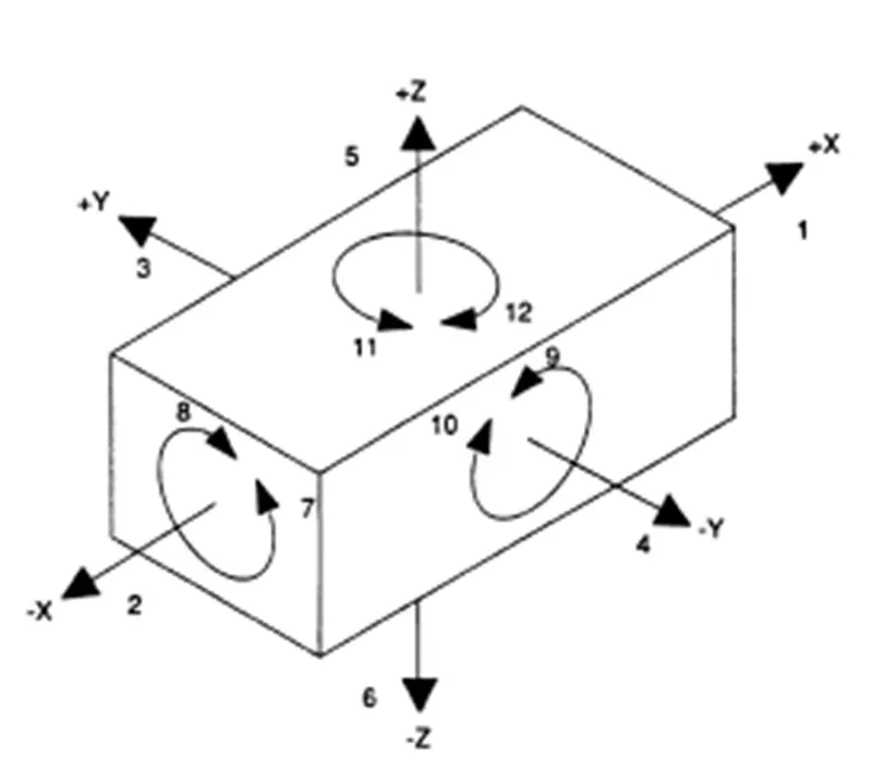
Pins A, B, C in the above image on the base plane( a plane parallel to the plane which contains X and Y axis) restrict the rotation of the component about X axis and Y axis. It also limits the downward movement of the component along the z-axis. 1,2,3,4 and 5 degrees of freedom is restricted. Pins D, E is in the plane parallel to the plane containing X and zaxes. It prevents the rotation of the component about the Z-axis(6, 7 degrees of freedom) and the movement of the body along the Y-axis towards one direction( 8 degrees of freedom). It facilitates the loading of the component in the fixture. This three degree of freedom may be restricted after loading of component by using clamping devices.
6) Define Body Coordinate system.
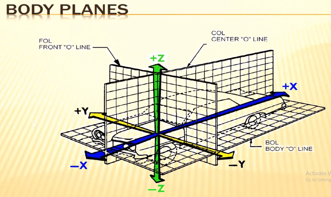
Body coordinate system(BCS) is also called car line or body line. Coordinate system is a reference system consisting of a set of points, lines and surfaces used to define position of point in space either in 2 or 3 dimensions.
Maintaining X,Y,Z coordinates in the fixture is a very important factor. We should try that the coordinates of the locating and clamping points should not be in three decimal. They should be in the whole numbers or max upto 1 decimal. Once these coordinates are maintained automatically the BIW base structure is maintained.
X direction is length of the body
Y direction is width of the body and
Z direction is the height of the body.
7) Elaborate Body plane system and its essentials.
Body planes are three mutually perpendicular imaginary planes. These are reference planes in automotive cars. These are used to define GD and T of all parts in the automotive domain. The measurement from body plane to parts are called body plane dimensions.
Body planes are essential because:
- It defines the exact position of each product in the vehicle wrt a fixed origin.
- It ensures flawless design for assembly.
- While designing lines , all the designs are carried out relative to the bodylines i.e. fixtures, turntables etc.
- It assists in easy location of different parts in the vehicle.
- It aims to create a standardised system.
- It assists in quality checks.