Week 9:- 2D Detailing Challenge
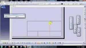
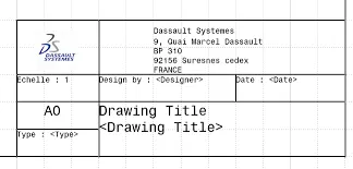
1.Drafting templates are used when standard symbols are to be drawn repeatedly. A drafting template is a flat piece of plastic with standard symbols cut in it. The drafting templates shapes are used as guides for drawing symbols on plans. Many templates are available for various architectural scales. The drafting templates are also available for a variety of floor plans and elevation systems. Included are doors, windows, plumbing fixtures, electrical devices, and landscape features.
Drafting templates are also available for circles, ellipses, lettering, flow charting, mechanical, and much more. We offer a complete line of templates for most needs. The templates are conveniently organized to help you locate the template you are looking for. If you can’t find the template you are looking for contact us, we have access to more.
2.The angle between the initial velocity of a body from a horizontal plane through which the body is thrown, is known as angle of projection
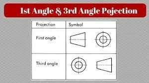
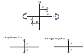
The two orthogonal projection methods used internationally are first angle projection and third angle projection. Third angle projection (figure 1.2) is used mainly in The United States and Canada whilst first angle projection (figure 1.1) is used mainly throughout Europe and the rest of the world.
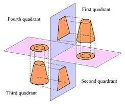
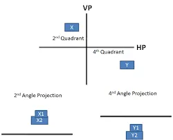
3.Overlapping projection views create confusion in the drawing. Therefore 2nd angle projection system is not used. Similarly when object is placed in 4th quadrant both top and front view will overlap. Therefore fourth angle projection is also not used
To get the first angle projection, the object is placed in the first quadrant meaning it's placed between the plane of projection and the observer. For the third angle projection, the object is placed below and behind the viewing planes meaning the plane of projection is between the observer and the object.
The projection symbol used to represent third angle projection shows what you would see when looking at the cone from the left, drawn sitting to the left of the drawing of the front face of the cone.
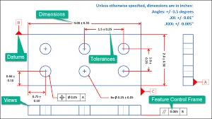
4.GD&T offers the ability to improve quality, decrease cost, and increase speed to market. The GD&T drawing is the continuous thread that connects the design and manufacturing teams and keeps everyone speaking the same language – literally
- Standardized, international system.
- More flexibility, particularly for complex shapes.
- Allows cylindrical tolerance zones.
- Datums are clearly defined.
- Based on the fit and function of a part or assembly.
- Eliminates the need for many notes.
- Allows for more tolerance.
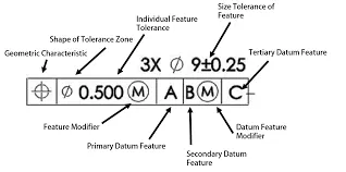
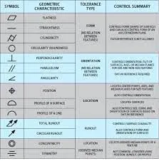
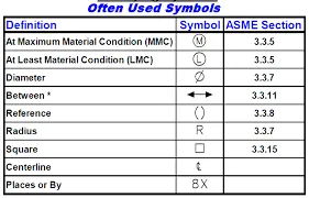
5.Currently, we have 16 symbols for geometric tolerances, which are categorized according to the tolerance they specify.Today, there are 14 types of geometric tolerances by the number of symbols, and 15 types based on classification. These are grouped into form tolerance, orientation tolerance, location tolerance, and run-out tolerance, which can be used to indicate all shapes.