Week 9:- 2D Detailing Challenge
1) Drawing Templates are the standard drawing files that are used to detail the 3D Models like part modelling, product layout, etc.
Drawing Templates:
- Drawing templates are basically the drawing standards as per customers specifications.
- Drawing templates are format that are used for detailing of different parts or units of the fixture.
- There are N numbers of details that are already available on the templates & are useful for various manufacturing processes such as machining finish, tolerances, surface treatments, material, name of the assemblies, etc.
- Preparing a drawing template at the start of the project can help us save time, as these templates can be used as a start model for detailing for different parts.
- Drawing templates also gives information about the angle projection to be used, views to be considered scaling of the drawing as per the part or unit.
Drawing templates contains a lot of information about the drawing as given below:
- Scale
- GD&T
- Roughness Symbols and standards
- Quantity
- Tolerances
- Sheet size and sheet number
- Type of projection (1st angle or 2nd angle)
- Notes about surface hardening and stress relieving
- Project code
- Part number
- Project name
- Company name
- Title
- Designed and checked by who
- Date
- Mass and density
- Allowance
2) To define an object, technical drawings use 2D views. This is called as orthogonal projection. The projection of the plane is viewed by the observer. The quadrants it should be only rotated in a clockwise direction.
The angles of projection are basically the view formats for orthogonal views of assemblies or panels. First and third angle of projection are majorly used in automotive standards. Understanding the angles of projection helps us to derive the actual image of 2D drawing.
The orthographic projection system is used to represent a 3D object in a 2D plane. The orthographic projection system utilizes parallel lines, to project 3D object views onto a 2D plane. According to the rule of orthographic projection. To draw a projection view of a 3D object on a 2D Plane. The horizontal plane is rotated in the clockwise direction.
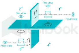
3) First Angle Projection:
In the first angle projection, the object is placed in the 1st quadrant. The object is positioned at the front of a vertical plane and top of the horizontal plane. First angle projection is widely used in India and European countries. The object is placed between the observer and projection planes. The plane of projection is taken solid in 1st angle projection.
Third Angle Projection:
In the third angle projection, the object is placed in the third quadrant. The object is placed behind the vertical planes and bottom of the horizontal plane. Third angle projection is widely used in the United States. The projection planes come between the object and observer. The plane of projection is taken as transparent in 3rd angle projection.
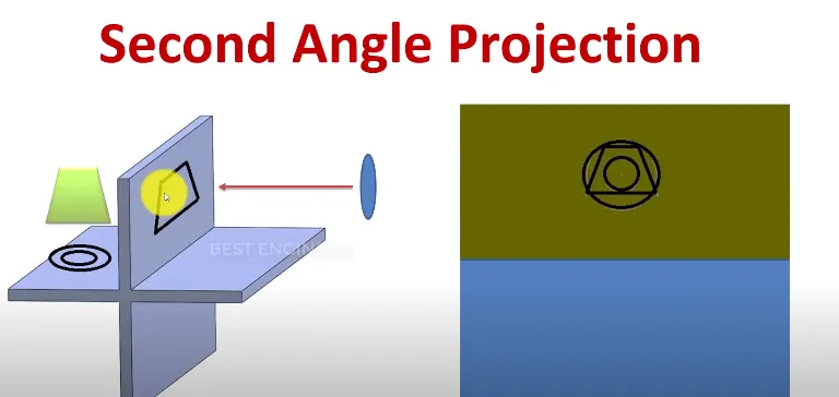
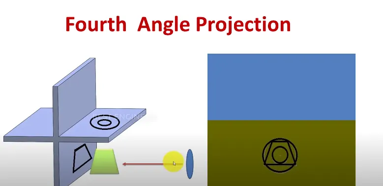
In Second quadrant, Vertical plane (VP) lies in between object and observer. Therefore, front view of the object will lie on vertical plane whereas top view will lie on horizontal plane. As per rule of projection when horizontal plane is rotated 90 degree in clockwise direction, top and front view will overlap.Overlapping projection views create confusion in the drawing. Therefore 2nd angle projection system is not used. Similarly, when object is placed in 4th quadrant both top and front view will overlap. Therefore, fourth angle projection is also not used.
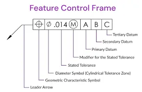
4) GD&T is an acronym that stands for Geometric Dimensioning and Tolerancing. It is a symbolic language used by designers to communicate manufacturing constraints and tolerances clearly. This information is conveyed in the form of annotations included in the design of the part.
Benefits of GD&T
- A standardized design language.
- A clear and precise way for the customer, supplier and production team to communicate.
- A method for calculating the worst case mating limits.
- Production and inspection processes are repeatable.
- Assembly is assured from quality production parts.
- Standardized, international system
- More flexibility, particularly for complex shapes
- Allows cylindrical tolerance zones
- Datums are clearly defined
- Based on the fit and function of a part or assembly
- Eliminates the need for many notes
- Allows for more tolerance
5) GD&T Symbols
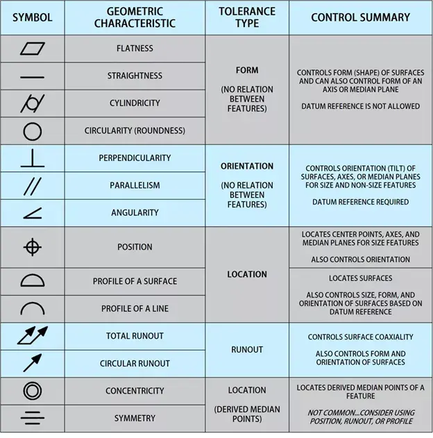
Form controls
- Straightness is divided into line element straightness and axis straightness.
- Flatness means straightness in multiple dimensions, measured between the highest and lowest points on a surface.
- Circularity or roundness can be described as straightness bent into a circle.
- Cylindricity is basically flatness bent into a barrel. It includes straightness, roundness, and taper, which makes it expensive to inspect.
- Line Profile compares a two-dimensional cross-section to an ideal shape. The tolerance zone is defined by two offset curves unless otherwise specified.
- Surface Profile creates through two offset surfaces between which the feature surface must fall. This is a complex control typically measured with a CMM.
Orientation controls
- Angularity is flatness at an angle to a datum and is also determined through two reference planes spaced the tolerance value apart.
- Perpendicularity means flatness at 90 degrees to a datum. It specifies two perfect planes the feature plane must lie in between.
- Parallelism means straightness at a distance. Parallelism for axes can be defined by defining a cylindrical tolerance zone by placing a diameter symbol in front of the tolerance value.
- Position is the location of features relative to one another or to datums and is the most used control.
- Concentricity compares the location of a feature axis to the datum axis.
- Symmetry ensures that non-cylindrical parts are similar across a datum plane. This is a complex control typically measured with a CMM.
- Circular Runout is used when there is a need to account for many different errors, such as ball-bearing mounted parts. During inspection, the part is rotated on a spindle to measure the variation or ‘wobble’ around the rotational axis.
- Total Runout is measured on multiple points of a surface, not just describing the runout of a circular feature but of an entire surface. This controls straightness, profile, angularity, and other variations.