Week 8 Worm Gear Challenge
Transient structural analysis of worm gear challenge using ANSYS Workbench:
AIM:
To study and perform transient structural analysis on the worm gear assembly as we need to cut the gear by half so as to bring the model within limits, and we have to rotate the worm so as to get to almost end of the half cut and get results for Equivalent stress, Equivalent elastic strain and the total deformation in the model and grid dependency test was also performed to optimize the element size for better accuracy.
ANALYSIS SETUP FOR WORM GEAR ASSEMBLY:
I. GEOMETRY:
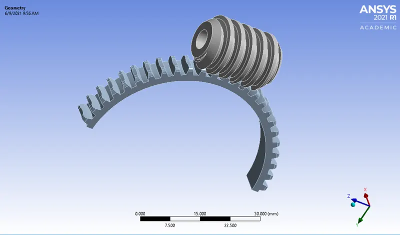
The CAD model of worm gear setup is imported in Ansys static structural environment. Then, the model is generated and checked if any abnormalities are present in the model. The worm gear setup consist of different bodies which are renamed accordingly as worm and worm gear. It is based on principle that worm in the worm gear drive may have single or multiple starts. Each full 360 deg turn of a single start worm advances the gear by one tooth. For a multi start worm the gear reduction equals the number of teeth on the gear divided by the number of starts on the worm. Both the sliding and the rolling actions of the worm and the gear come into play during the meshing of the gears. The sliding contact dominates at high reduction ratios. Much heat is produced due to friction while sliding, which limits the efficiency of worm gears to 30 to 90 percent. The worm and the worm gear are made up of dissimilar metals in order to minimize the friction and loss in efficiency.
II. MATERIALS:
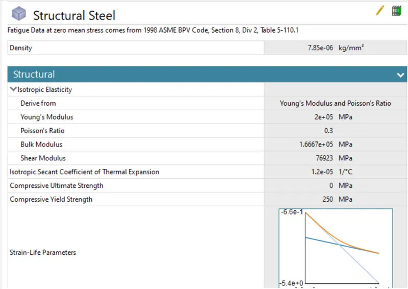
Below are the materials which is used to perform analysis for the worm gear setup. The analysis is carried out for each material individually.
Worm: Structural steel
Worm gear: Structural steel
The details of each material has been carried out below as shown in the image:
III. CONNECTION DETAILS:
A. CONTACT DETAILS:
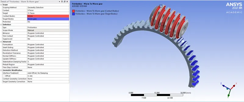
Frictionless: Worm to Worm gear-
Frictionless contact is given below between faces of worm and worm gear as shown in the image below. The 9 faces of worm came in contact with 31 faces of worm gear with type of contact as frictionless. Lastly, the scope mode is made to manual.
B. JOINT DETAILS:
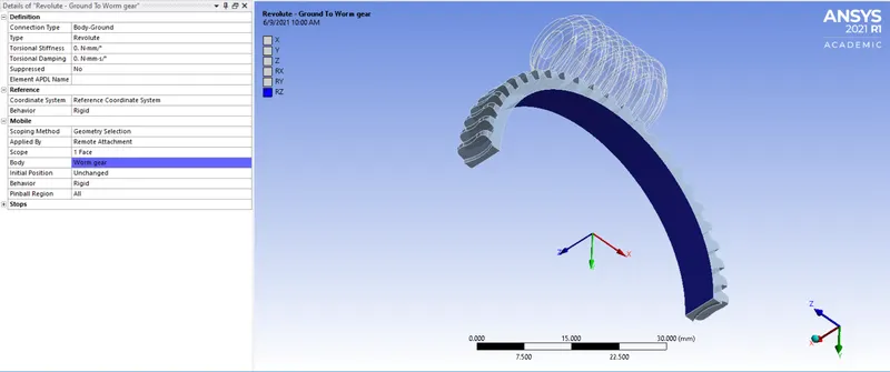
1. Revolute-Ground to Worm gear:
In this joint, we have to select the worm gear as geometry selection part. Then we have to change the connection type and connection as 'Body-ground' and 'Revolute'. This joint is applicable to the worm gear relative to the ground so that it will allow only axial rotation.
2. Revolute-Ground to Worm:
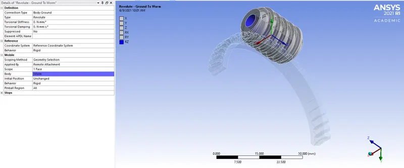
In this joint, we have to select the worm as geometry selection part. Then we have to change the connection type and connection as 'Body-ground' and 'Revolute'. This joint is applicable to the worm relative to the ground so that it will allow only axial rotation.
IV. MESH:
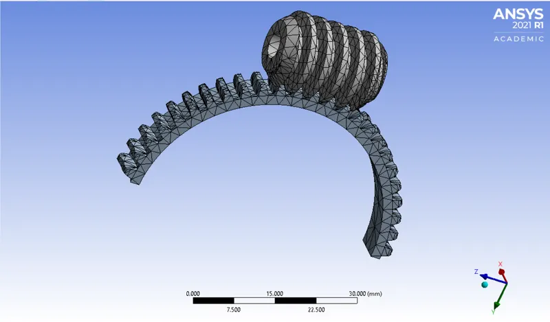
- Basically, we have preferred default mesh of 5 mm for whole setup.
- Likethat, we have generated the fine mesh which is sufficient to carrry out simulation which gives desired results.
V. ANALYSIS SETTINGS AND BOUNDARY CONDITIONS:
A. ANALYSIS SETTINGS:
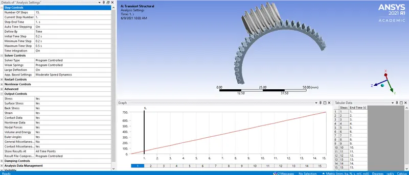
For this analysis the number of steps is set to 15 with Auto Time stepping is ON and it is defined by time, hence initial, maximum and minimum time will be 0.2, 0.5, 0.2 sec respectively. After that, the solver type is to be Program controlled and then Large deflection is set to On, so as to account for change in stiffness due to change in shape of gears. When stabilizers are activated, it add dampers to all nodes. When the large displacement nodes try to move the force is added to balance them thus favoring convergence. Hence, the energy dissipiation is said to be Program controlled. Lastly, we have to enable all output controls to be ON except contact miscellaneous.
B. BOUNDARY CONDITIONS:
Joint-Rotation:
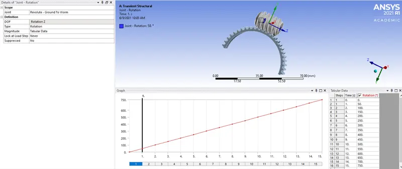
Basically, we have selected joint as Revolute-Ground to Worm. Then, we have taken DOF and its type as 'Z Rotation' and 'Rotation'. Likewise, we have given rotation in tabular form. The rotation is given in the form of angle 50 deg.
VI. POST-PROCESSING RESULTS:
Now, we have to compare the deformation and stress on the basis of different materials. Then, we have to analyze the result for total deformation, equivalent stress and strain for worm gear setup. The results are as shown below:
I. Total Deformation:
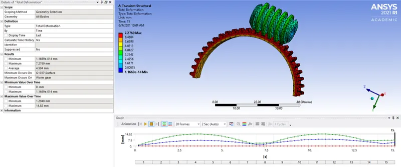
- Here we have applied the rotation to the worm upto 15 or upto 750 deg.
- So, the deformation will not be higher for worm, but higher deformation will take place to the gear, as it is in big size and for one rotation or 750 deg of the gear, number of rotation of the worm will be more, so the larger deformation in terms of displacement can be seen at gear.
II. Equivalent stress:
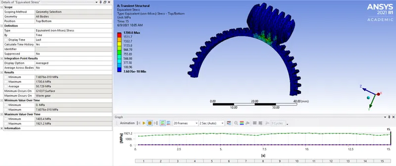
- Here from the plots and data we can see that the stress on the teeth of worm and gear is increasing and decreasing in a cyclic form.
- Increase and decrease in the stress is nearly similar.
- The change in this type of stress graph is due to engagement and disengagement of the teeth of the gear with the worm.
- Stress is generating very high up to 1700.6 MPa.
- During the transmission of the motion, higher stress is generating.
- We can see the higher stress are concentrated at the edges or contact portion of the teeth or we can say the contact faces of the worm and gear are facing higher stress.
- Since the value of the stress is exceeding the yeild strength of the structural steel, it can fail.
III. Equivalent elastic strain:
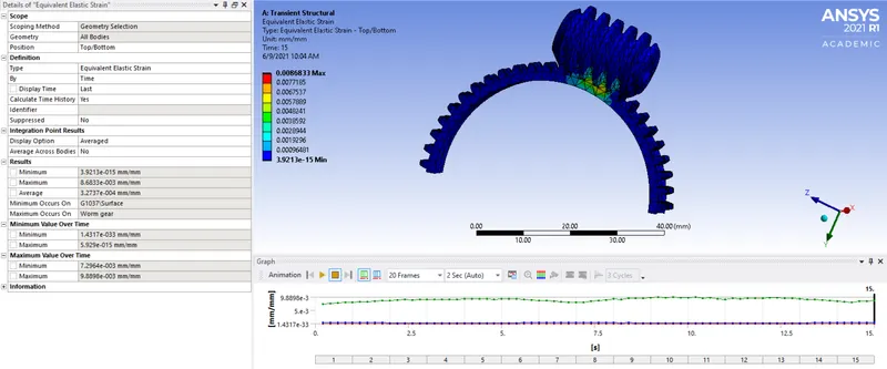
- Here we can see the max. strain value is 0.0086.
- Also the rate of the strain is not so high. We can see some spikes in the graph where the strain is increasing, so the amount of percentage elastic strain for failure is low.
- So the failure of the worm or gear teeth is not happening at higher strain rate or due to plastic strain.
VII. POST-PROCESSING RESULTS:
|
Parameters |
Worm gear assembly |
|
Maximum Total Deformation |
7.2769 mm |
|
Minimum Total Deformation |
1.1669e-014 mm |
|
Maximum Equivalent elastic strain |
8.6833e-003 mm/mm |
|
Minimum Equivalent elastic strain |
3.9213e-015 mm/mm |
|
Maximum Equivalent stress |
1700.6 MPa |
|
Minimum Equivalent stress |
7.6076e-010 MPa |
CONCLUSION:
- From the results we can conclude that the worm and gear assembly should be made out of different material to minimize the stress and pressure and to reduce the loss of efficiency.
- Generally the worm and worm gear are used with different material to reduce friction and for better transimission.
- Also due to sliding, heat may generate, which reduced the efficiency, so use of dissimilar material is necessary.
- With large number of starts of worm and comparatively large number of teeth of the gear can improve the transmission ratio very high.
- Shape of the worm is slim compared to gear, so higher tooth forces lead to higher deflection of the worm shaft, which can have negative consequences for the wear load capacity as well as the efficiency.
- So, for required power density, there should be advancements in bronze material, lubricants and manufacturing quality.