Week 8 Worm Gear Challenge
Worm Gear Assignment –
Objective –
The objective of this assignment is to simulate a worm gear assembly and perform transient analysis on it and plot the results.
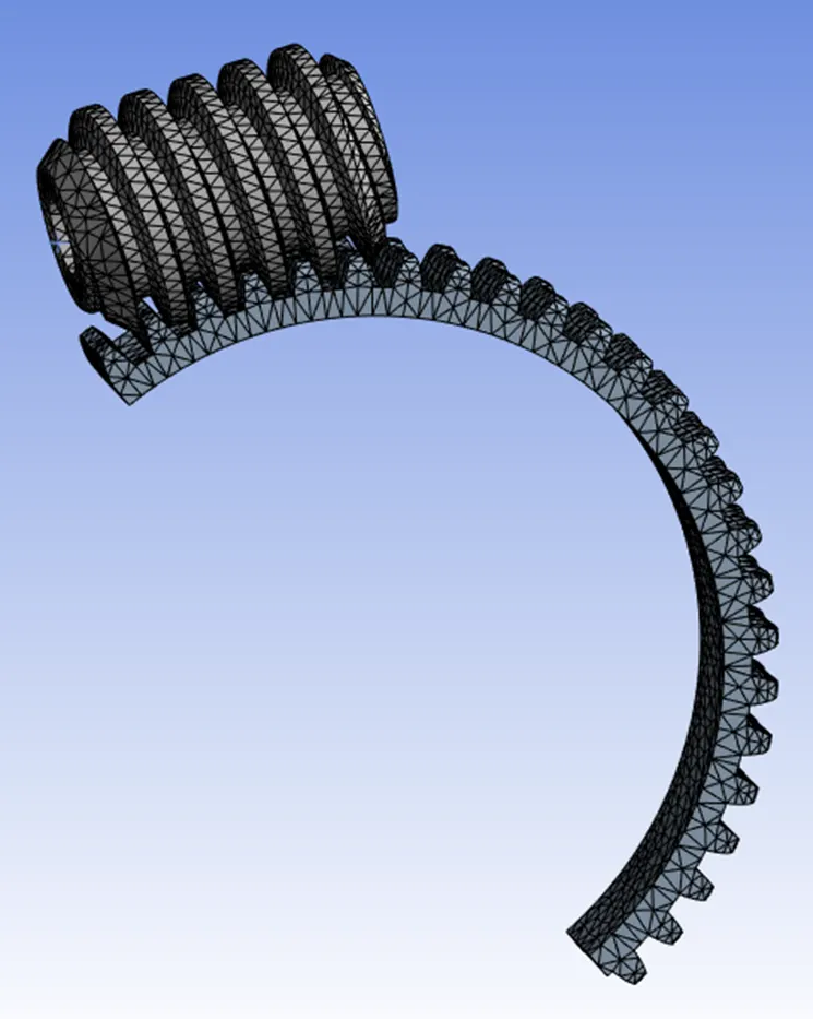
The analysis is performed on half section of the gear to reduce the simulation time and achieve finer mesh.
Model and Analysis Set up
- Model Geometry
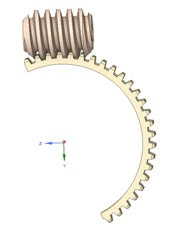
The model is created in a CAD software and imported in ANSYS, initially checked in Space claim.
The model is further repaired in Space claim using the ‘Split Body’ function to cut the gear in half section
See below model snapshot.
- Materials
All the materials to be Structural Steel for all the parts
- Contacts and Joints
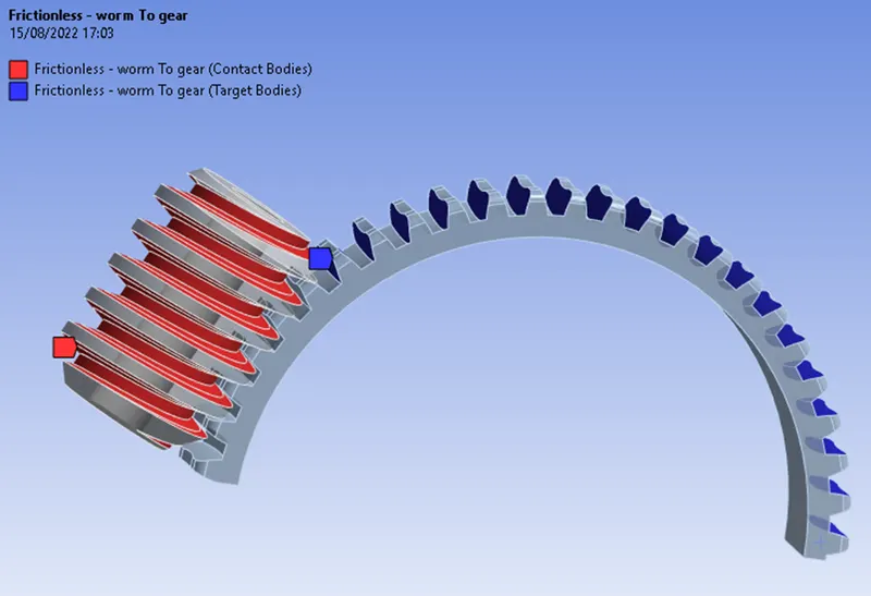
Frictionless contact is defined between the teeth of the worm and gear as shown below
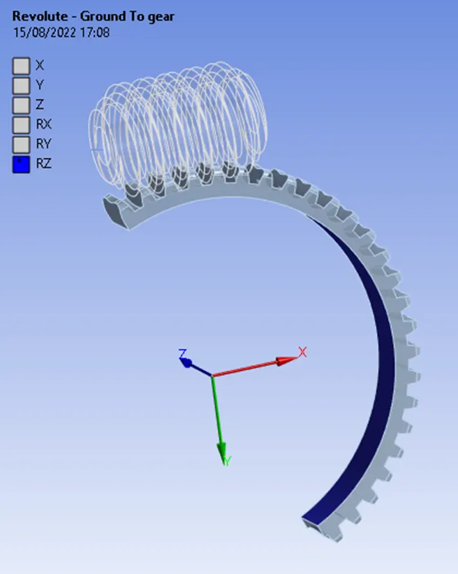
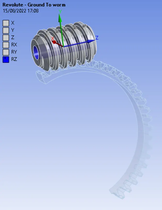
Joints are defined as below –
- Body to Ground - Revolute Joint for the Gear - so that it can rotate about the Z axis
- Body to Ground - Revolute Joint for the Worm - so that it can rotate about the Z axis
- Meshing
The model is meshed with the element size of 1mm throughout with following attributes
Adaptive Sizing – Yes
Smoothening – Medium
- Analysis Settings
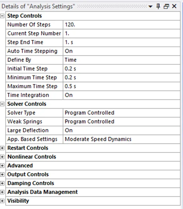
The analysis is performed in 120 steps for the gear to rotate complete 180 deg. and the analysis settings as below
- Joint Loads
Joint Rotation is applied on the revolute joint of the worm, in 120 steps and increment of 50 deg. for each step.
The model is solved for the results, and the required results are plotted as below
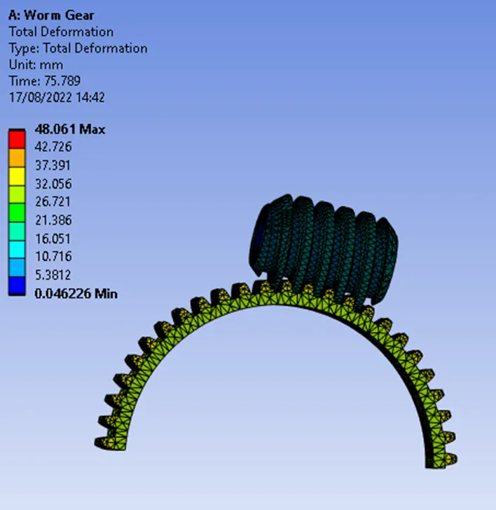
- Total Deformation
The total deformation = 48.06 mm on the gear
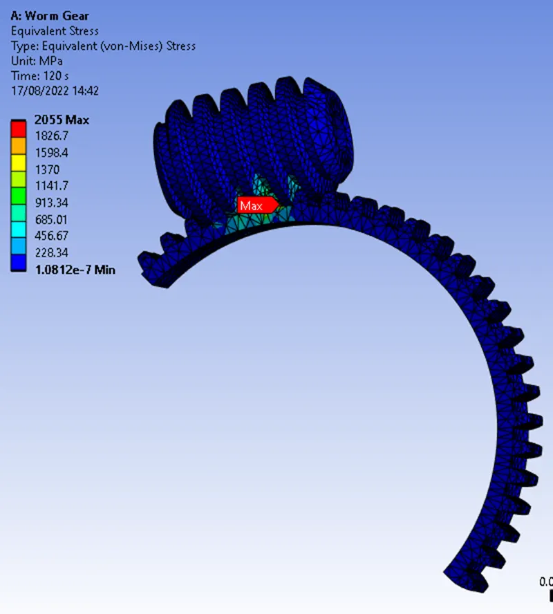
- Equivalent Stress
The maximum stress on the tooth of the gear – 2055 MPa
- Equivalent Strain
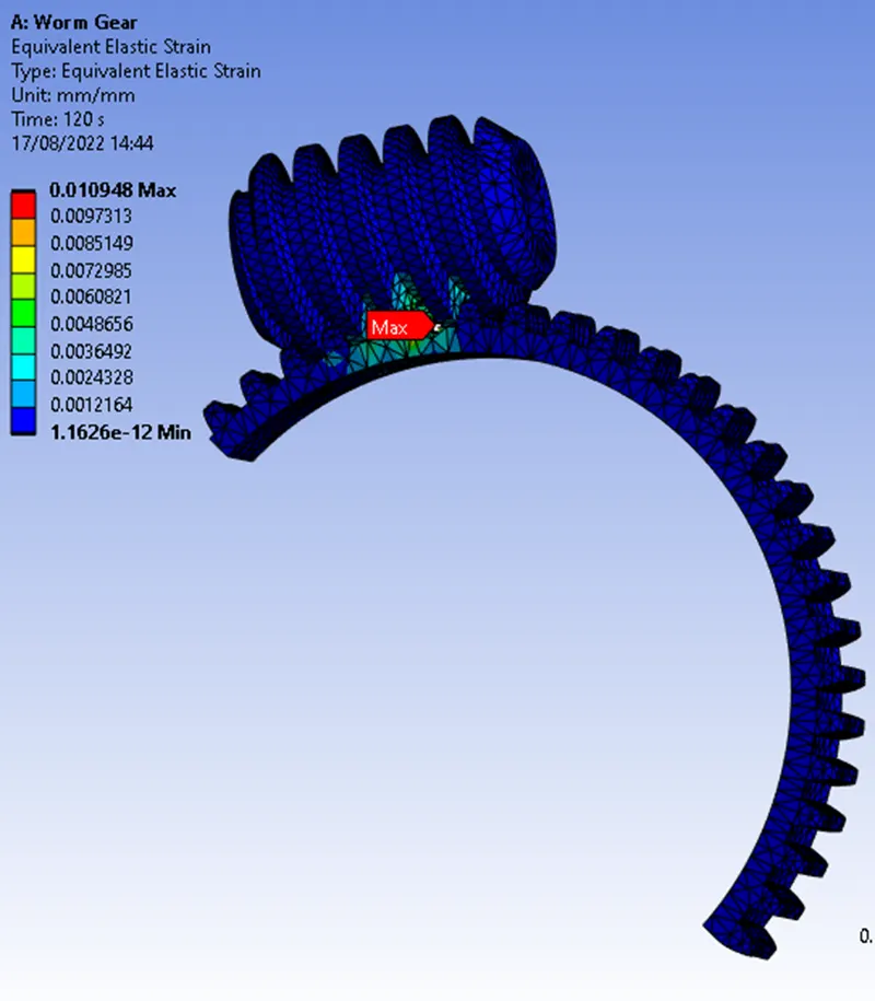
- Results and Conclusion
The results are tabulated as below –
|
Design Case |
Deformation (mm) |
Maximum Stress (MPa) |
Maximum Strain |
|
Gear Rotated at the end of half cut |
48.06 |
2055 |
0.0109 |
- The deformation plot shows even deformation throughout the gear meaning the gear is rotating in constant motion.
- High Stresses and Strains are developed on the tooth junction with the gear body which are highly localised and mainly due to the sudden change in the geometry.
- The worm needs to rotate by 6000 deg. to generate 180 deg. rotation of the gear
- The velocity ratio of this assembly is 9.74