Week 8 Worm Gear Challenge
Aim: To analyse a worm gear in Ansys Workbench.
Objective: To perform a transient structural analysis on a worm gear assembly. To rotate the worm so as to get to almost end of the half cut and get results for Equivalent stress, Equivalent elastic strain and the total deformation in the model. You can use a finer mesh while performing the challenge and submit a well formatted report with appropriate images.
Introduction:
A worm gear is a staggered shaft gear that creates motion between shafts using threads that are cut into a cylindrical bar to provide speed reduction. The combination of a worm wheel and worm are the components of a worm gear. Speed reduction is determined by the number of worm threads and the number of teeth on the worm wheel. The advantages of worm gears include noise and vibration reduction as well as compactness. They are made of hardened metals because of the amount of heat they generate.
A worm gear is the most compact type of gearing system. They are capable of being placed in very small spaces and still providing high ratio speed reduction. With proper mounting and installation, worm gear systems operate smoothly and quietly.
The typical method for manufacturing worm gears is hobbing using a hob or cutting tool; this cutting tool is similar to the gear with which the worm gear will mate. Worms can be turned, hobbed, milled, or ground.
Procedure:
- After opening Ansys Workbench, use explicit dynamics as the mode of analysis for simulation.
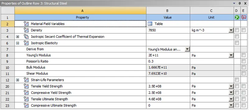
- Now, add Structural Steel from the engineering data tab in project menu.
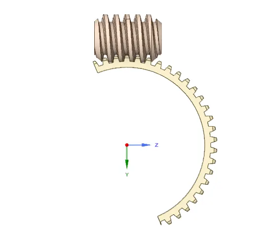
- Import the model provided and check the geometry in the Ansys Spaceclaim for any abnormalities. Dividing the gear into two for creating better mesh by using plane.
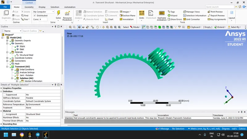
- Now in Ansys mechanical, rename the components and assign the material structural steel.
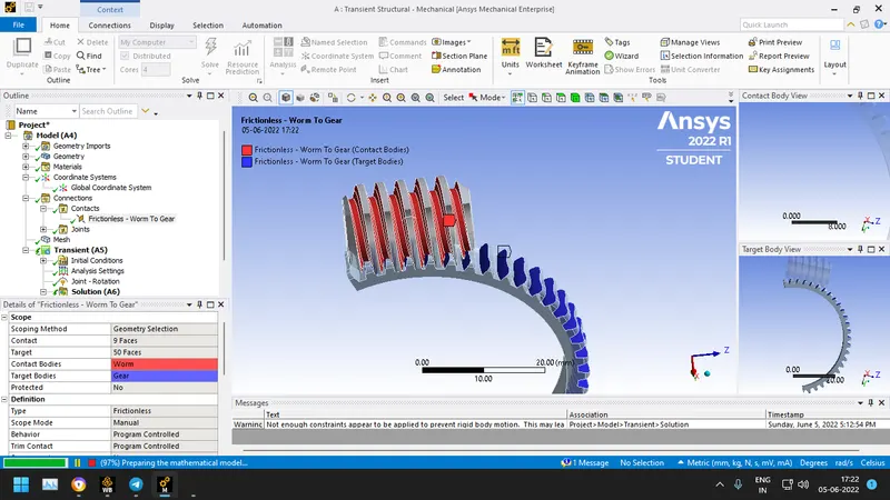
- Now, add to the existing default contacts created by ansys required for the simulation. We'll create the joints as given below as
Frictionless contact between worm and gear:
Revolute ground to body for both worm and gear:
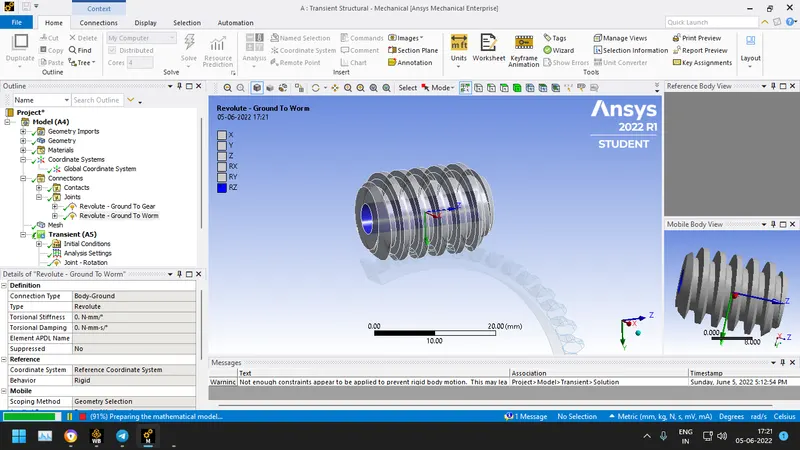
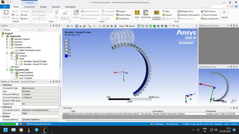
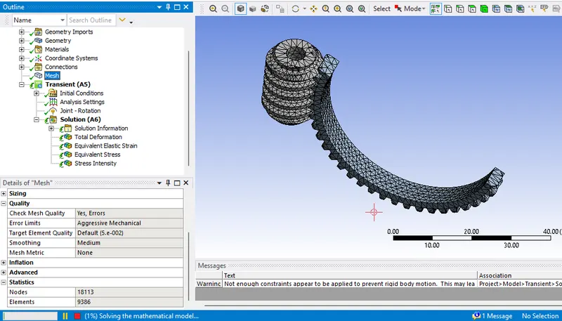
- Mesh the components with 1.5mm element size. Final Mesh obtained is:
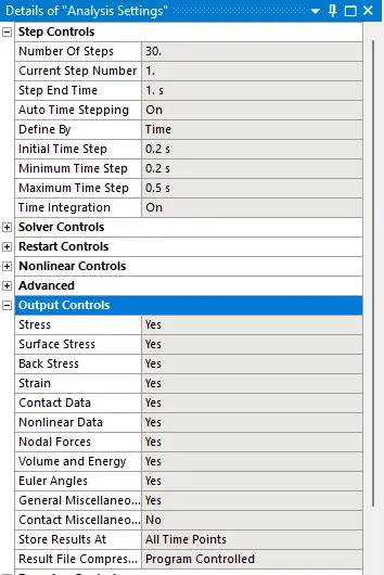
- Following analysis settings have been used for the simulation with 30 steps.
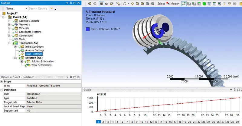
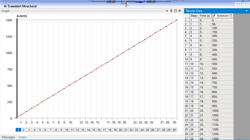
- Adding joint rotation in z direction for a rotation of 3000 degree with 30 steps of 50 degree increment each.
- Insert total deformation, equivalent elastic strain and equivalent stress and as required.
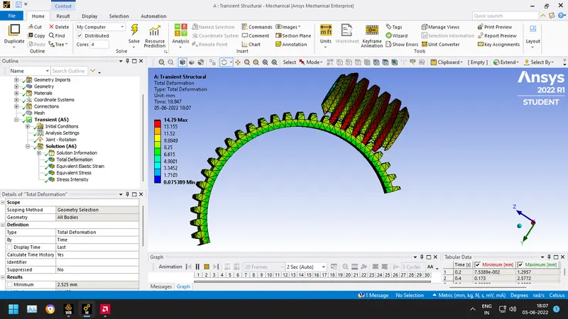
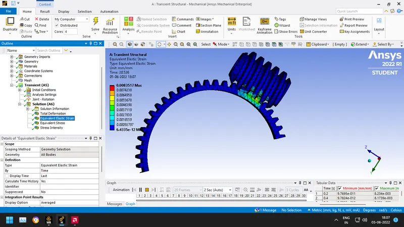
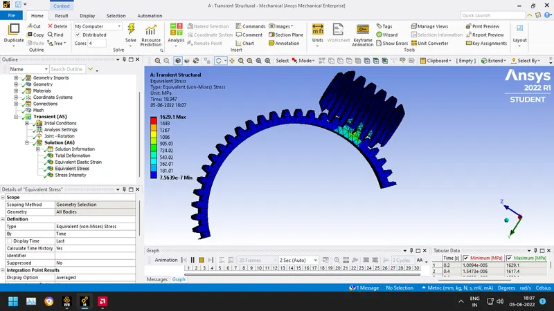
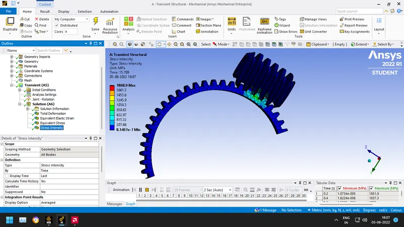
- Finally following solutions have been obtained after running the simulation for the worm gear:
CONCLUSION:
The results observed above are as follows:
The max Equivalent stress is 1629.1 MPa.
The max Equivalent elastic strain is 0.0083.
The max total deformation is 14.79 mm.
The max stress intensity is 1868.9 MPa.