Week 8 - Universal Joint
Aim: To analyse a double universal joint in Ansys Workbench.
Objective: To perform transient structural analysis on a double universal joint with a spring using three different materials: Structural Steel, Stainless Steel and Titanium Alloy where the three materials must be used on the joint with the springs alone. Use a refined mesh if possible for the academic license. Obtain the Equivalent stress and total deformation for all the three cases and compare them.
Introduction:
A universal joint is a connection between two objects, typically shafts, that allows relative rotation in two axes. It is made up of two revolute joints with perpendicular and intersecting axes.
When shafts are connected using a universal joint, each shaft terminates in a revolute joint with its axis perpendicular to the shaft’s rotational axis. This allows rotary motion to be transferred between the shafts while allowing misalignment in both remaining rotational degrees of freedom. A single rotational degree of freedom is constrained (the shaft rotation) as well as all relative translations, giving a universal joint two degrees of freedom (2-DOF).
Universal joints have been extensively used in vehicle drivetrains — but are being replaced by constant velocity joints. Universal joints are now rarely used to transmit power to the front wheels of vehicles, except for some heavy duty off-road vehicles. They remain widely used for drive shafts, although constant velocity joints are even starting to be used for these applications. Universal joints also have many other uses in mechanical control systems and industrial machinery. Universal joints allow large angles between shafts.
Procedure:
- After opening Ansys Workbench, use explicit dynamics as the mode of analysis for simulation.
- Now, add Structural Steel, Stainless Steel and Titanium Alloy from the engineering data tab in project menu.
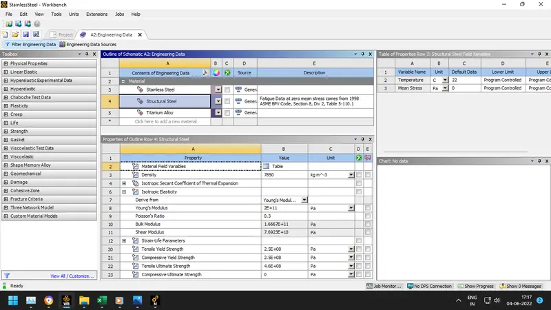
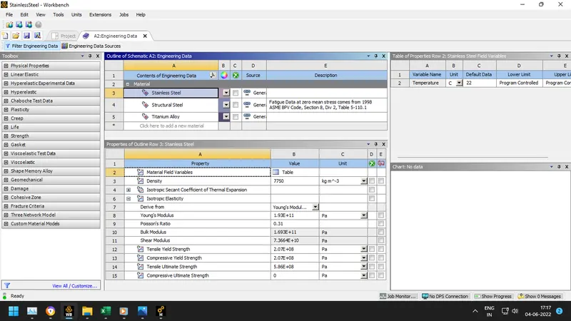
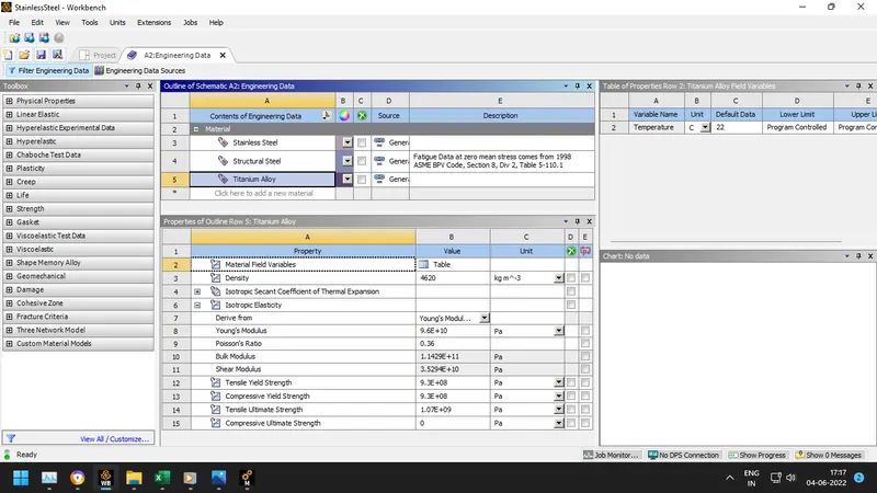
- Import the model provided and check the geometry in the Ansys Spaceclaim for any abnormalities.
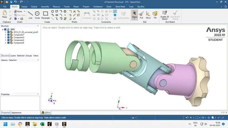
- Now in Ansys mechanical, rename the components and assign the material structural steel.
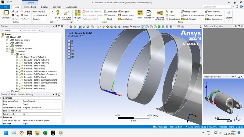
- Now, delete the default contacts created by ansys because no contacts are required for the simulation. We'll create the joints as given below as
Fixed ground to body at the end of the of the spring.
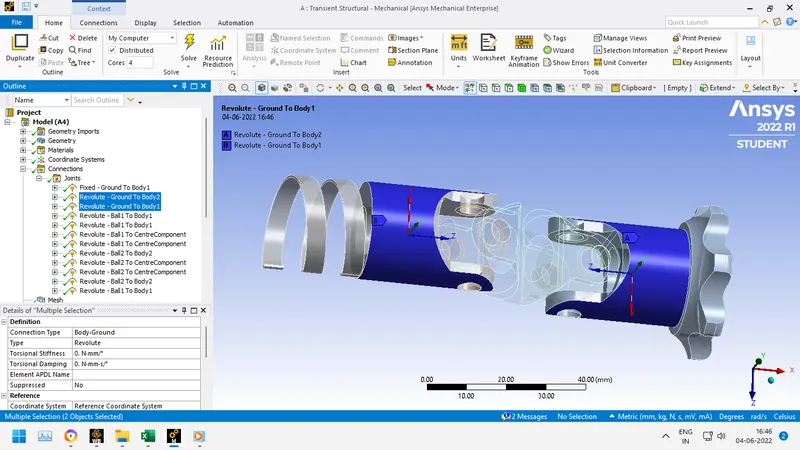
Revolute ground to body for the following
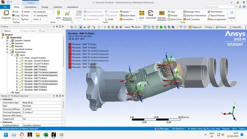
Revolute body to body for the following
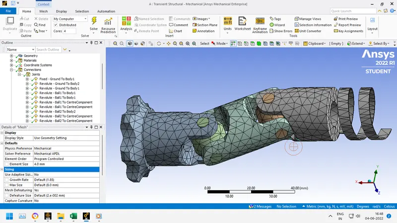
- Mesh the components with 4mm element size. Final Mesh obtained is:
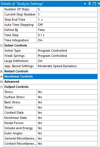
- Following analysis settings have been used for the simulation with 5 steps.
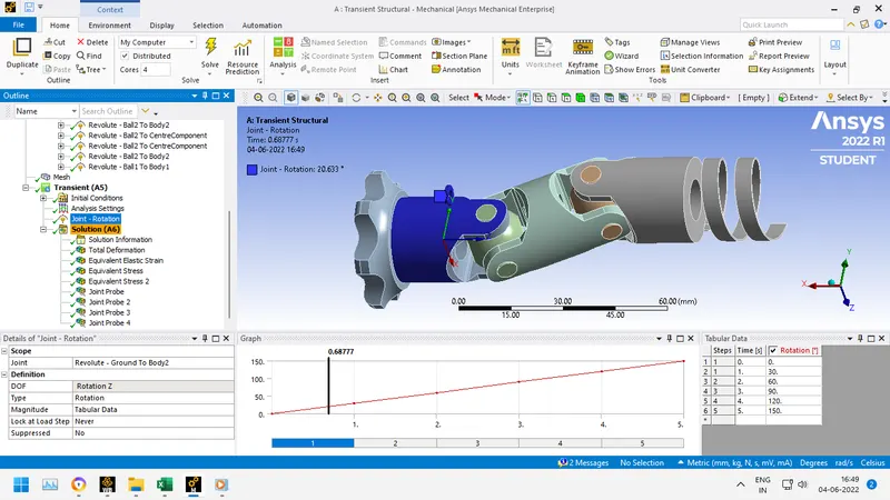
- Adding joint rotation in z direction for a rotation of 150 degree with 5 steps
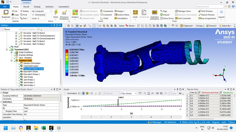
- Insert total deformation, equivalent elastic strain and equivalent stress and as required.
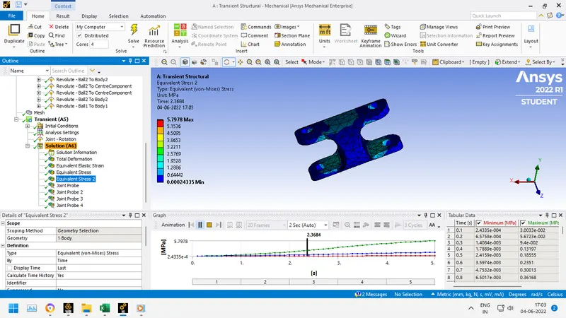
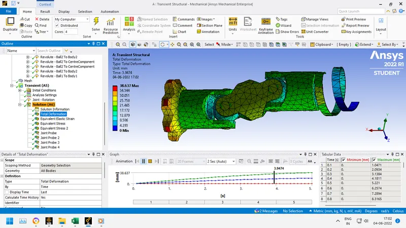
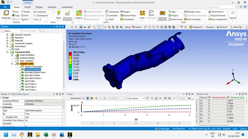
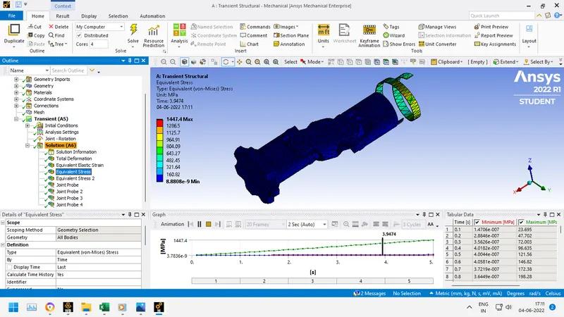
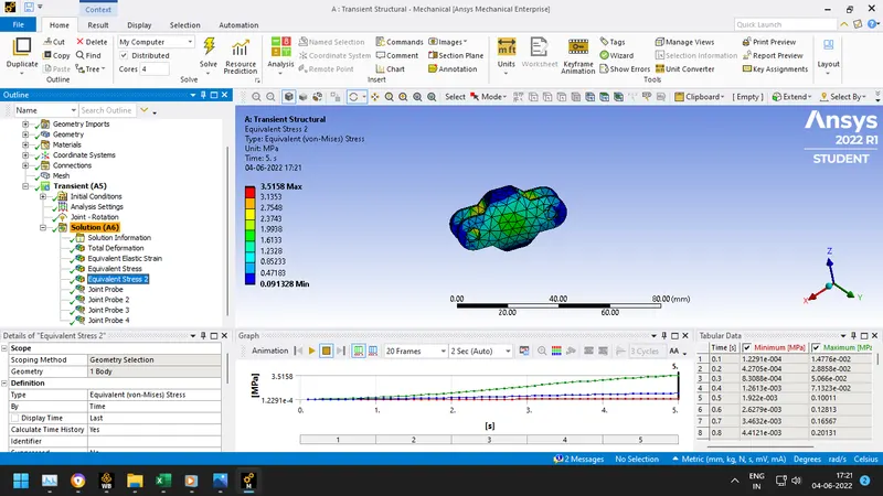
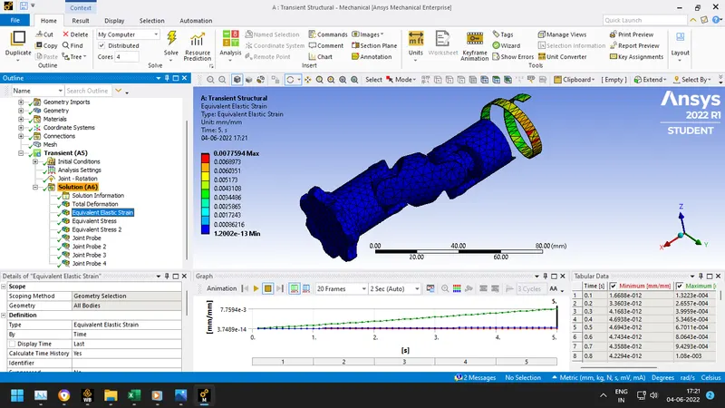
- Finally following solutions have been obtained after running the simulation for the double universal joint.
For Structural Steel
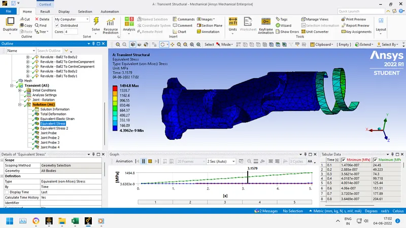
- Follow the same procedure mentioned above for stainless steel and titanium alloy.
For Stainless Steel
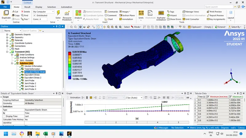
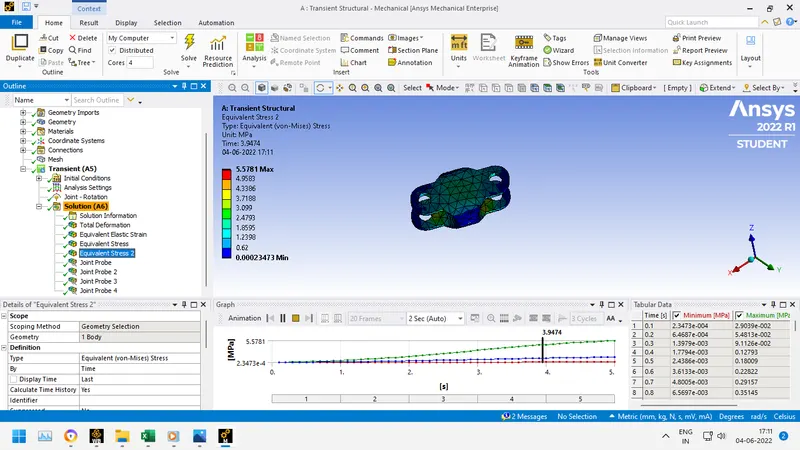
For Titanium Alloy
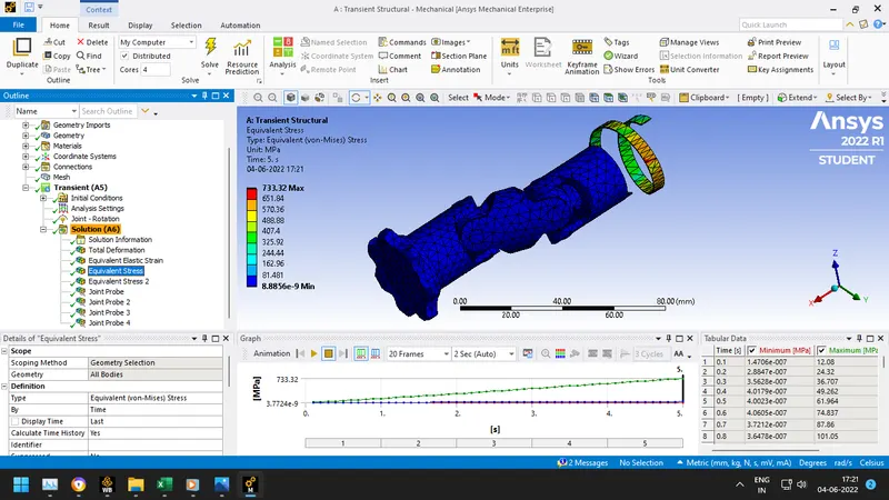
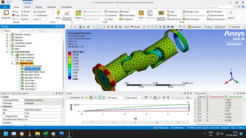
CONCLUSION:

From the above table, we can see that the maximum stress induced on the double universal joint and just the joint is in a material made up of structural steel. The total deformation and equivalent elastic strain almost remains to be same.
But if a material is to be chosen from the materials present above, Titanium alloy is the best beacuse least amount of stresses are induced on the double universal joint and also on just the joint itself.