Week- 8 - Solid meshing
2D MESHING OF A PLASTIC COMPONENT (Rearview Mirror) WITH THE GIVEN QUALITY CRITERIA
Aim : For the given Rearview mirror model, Check the geometrical errors after that mesh the surfaces with the 2D and 3D element Quality criteria.
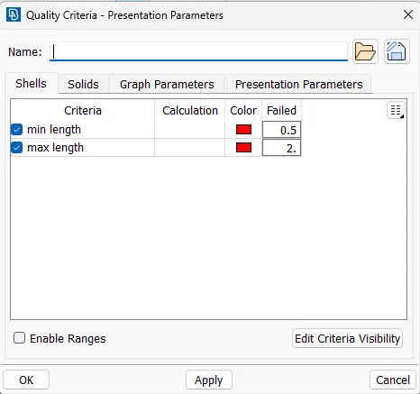
Given Quality requirements :
| S.N | Quality Criteria | Value |
|
1 |
Target/Average length |
1 |
|
2 |
Minimum Length |
0.5 |
|
3 |
Maximum Length |
2 |
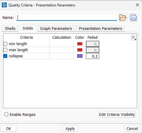
| 4 | Tet collapse | 0.2 |
Procedure :
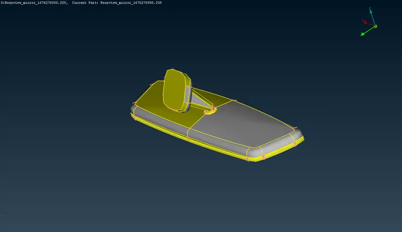
- The Rearview mirror model is opened in the ansa software and the model initially contains only edges of 'single cons' indicating that the individual edges are not connected to their corresponding surfaces as shown in the figure below. The red color on the edges indicates the same.
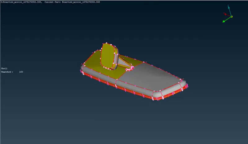
- The 'Topo' option is used and the whole model is selected and by clicking the middle mouse button it connects all the corresponding surfaces making it a 'double cons' edges which is indicated by the color 'yellow'.
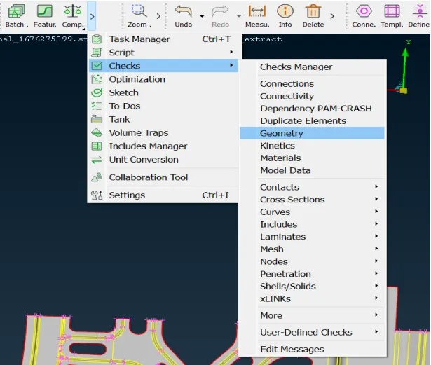
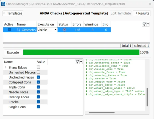
- The whole model has to checked for any geometrical error before the meshing can be started. The whole model is selected and the 'Check' option is clicked and the 'Geometry' option is selected which opens up a geometric check window, where all the required checks are selected and is executed as shown in the below figure.
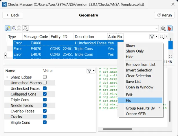
- All the errors obtained are selected simultaneously and with the right click of the mouse the fix option is selected.
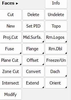
- The errors which are left are corrected manually using the commands like ‘Delete’ and ‘New’ in the Faces window.
- Once the Geometric correction is done, the F11 key is pressed and required Quality criteria is set.
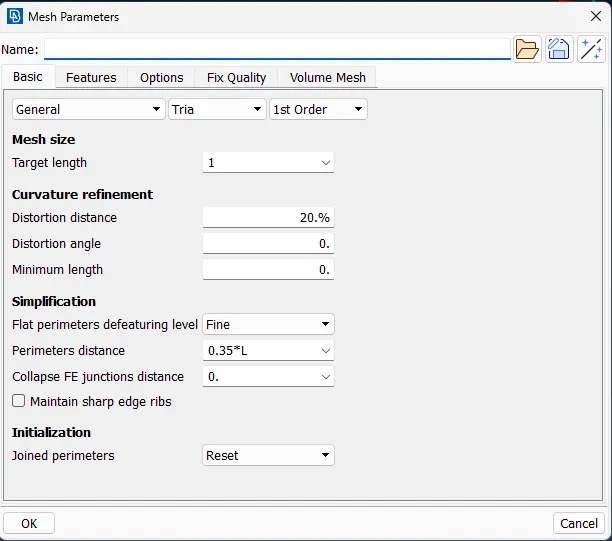
- Similarly the required Mesh parameters are also set. The Mesh elements are selected as 'Tria' for the meshing of surfaces in the 3D model.

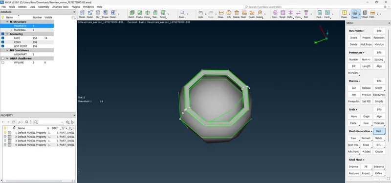
8. Once the model is free from all the Geometric errors, then individual PID's are selected from the Property window and the 2D meshing is started using the 'Best' command as shown below.
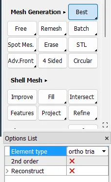
9. The 'ortho tria' elements are used to create mesh for the curved surfaces and normal 'tria' for the flat surfaces.
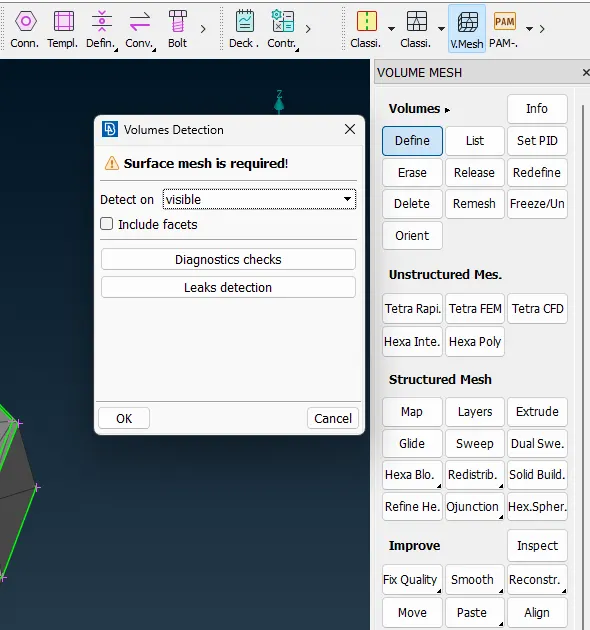
10. Now the 2D mesh has to applied to the whole 3D model using the Volumetric mesh option and selecting the 'Define' command which selects the PID on which the Volumetric mesh to be generated.
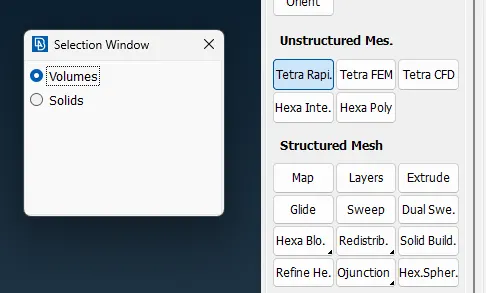
11. Use the command 'Tetra Rapid' to apply 3D mesh on the entire volume of the model. Once the volumetric mesh is completed it can be examined using the 'Not' command as shown in the figure below.
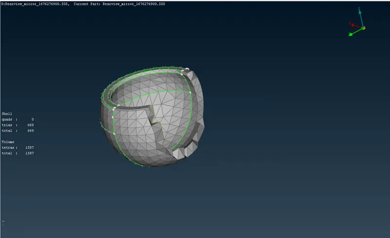
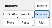
12. The quality criteria errors formed are corrected using the 'Reconstruct' and 'Smooth' commands.
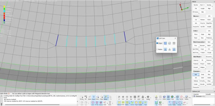
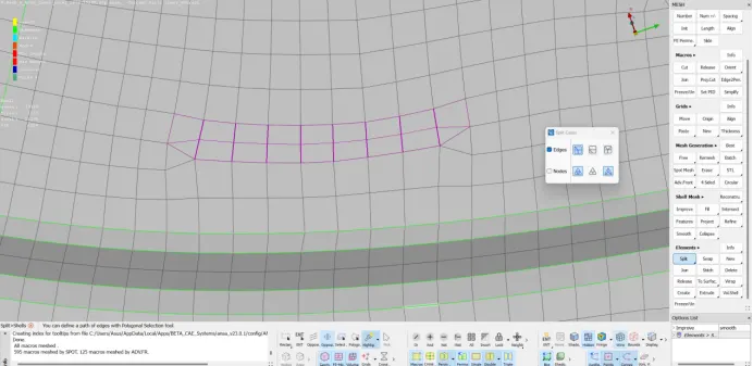
13. Volumetric mesh is created for the rest of the PID's using the similar steps and the quality errors are eliminated before the 3D mesh is created for the PID. The 2D trias are reduced using the ‘Split’ , ‘Join’ and ‘Swap’ commands in Elements window.
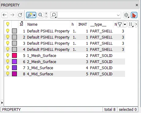
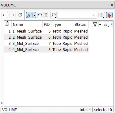
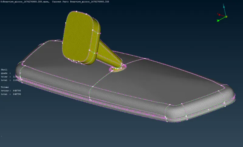
14. The final model with the complete 3D mesh, final property list and the volume list consisting of all the PID's is has shown in the figure below.