Week- 8 - Solid meshing
REPORT ON SOLID MESHING
OBJECTIVE :
To check the geometrical errors and mesh the Surfaces with the given 2D element Quality criteria for the Rear View Mirror.
PROCEDURE :
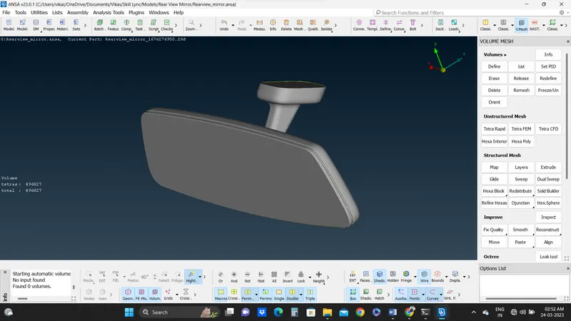
- The below is the provided Rear view mirror geometry which is to be meshed (Fig.01).
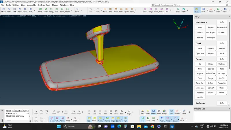
Fig. 01
- I have gone through the geometry of CAD model for any irregularities and applied TOPO.
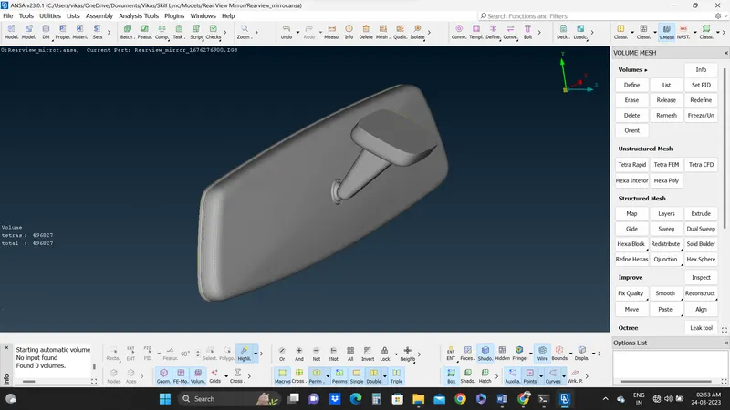
- I applied perimeter length 1 mm for refining and smoothing the Cons and edges (Fig.02).
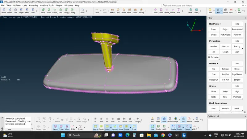
Fig. 02
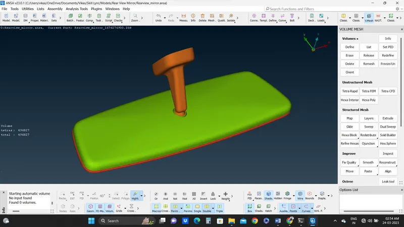
- Applied check geometry to check the CAD geometry for any errors before proceeding for meshing. The geometry check passed without any errors (Fig.03).
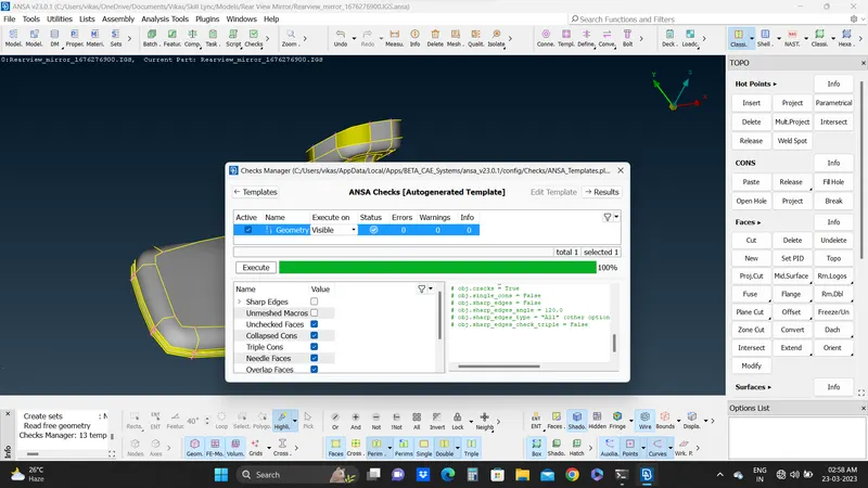
Fig. 03
- In Mesh parameters, I selected ortho tria as element type and entered minimum length 0.5 mm and in Quality Criteria, I selected Collapse 0.2 mm in Solids.
- Now, I proceed with one part at a time from properties by switching ON/OFF parts.
- I selected a single part and then applied Best mesh option from Mesh Generation. I used ortho trias for curved surfaces and trias for flat surfaces.
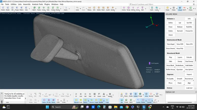
- Then, in Volume Mesh I selected Define and applied visible. On next window, I selected unstructured mesh type with Tetra Rapid and entered maximum thickness as 2 mm (Fig.04) and remeshed.
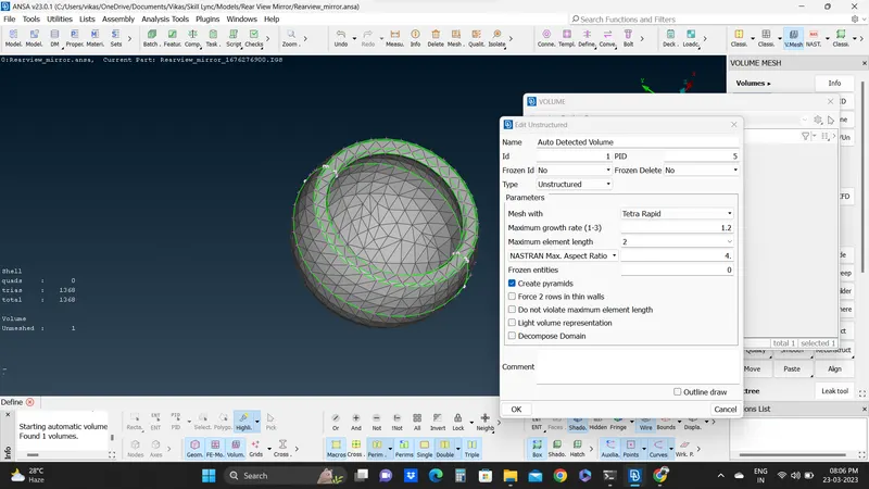
Fig. 04
- Below are the figures of parts meshed separately (Fig.05, 06, 07, 08).
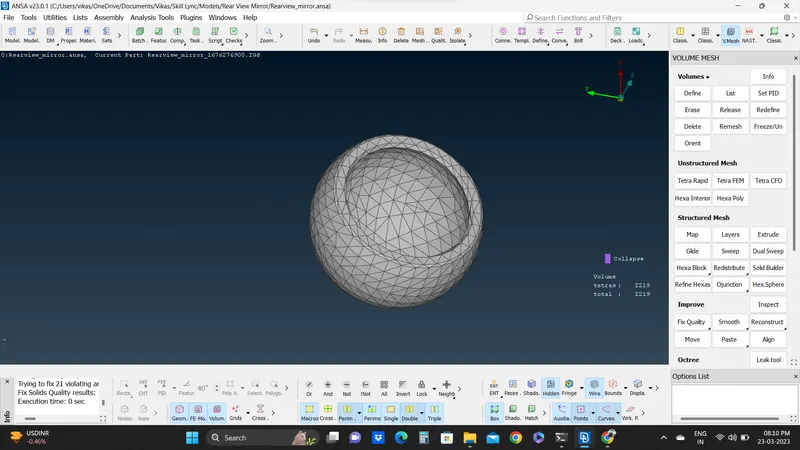
Fig. 05
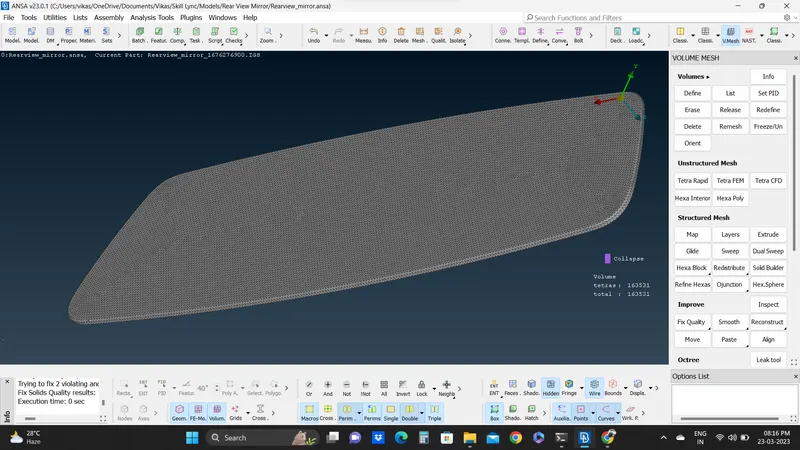
Fig. 06
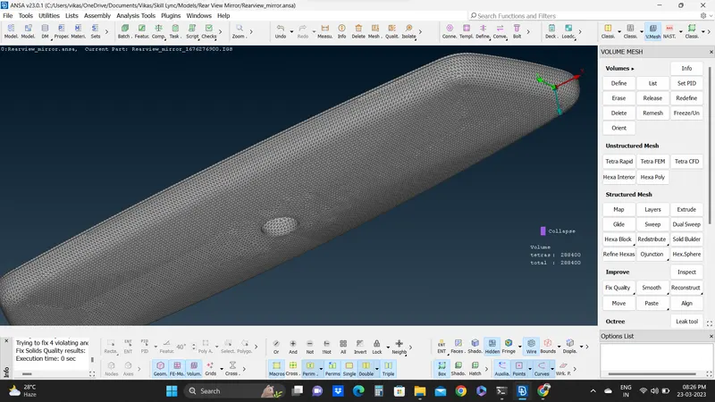
Fig. 07
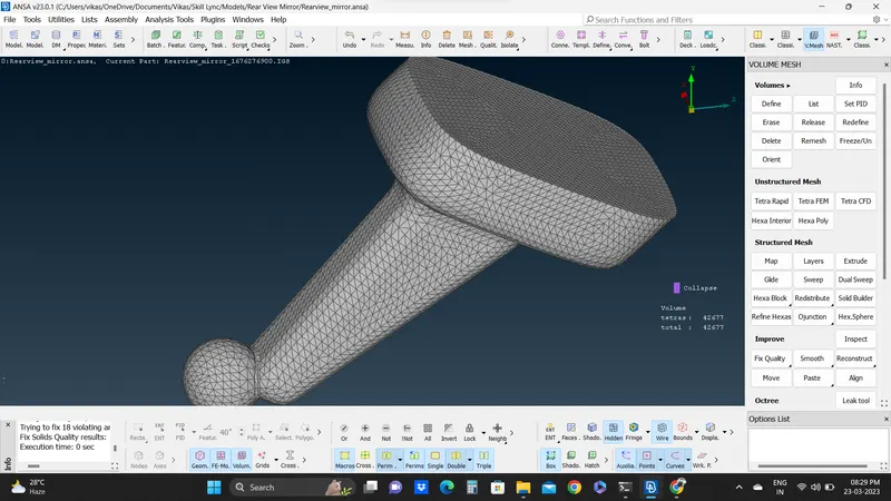
Fig. 08
CONCLUSION :
Learned about Solid Meshing and it is very easy to apply.
FINAL MODEL IMAGE :