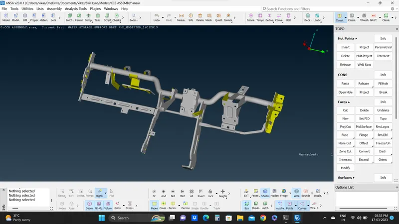
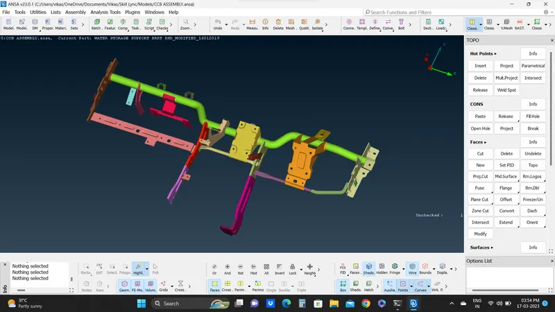
Week 4 - 2D Meshing for Sheet Metal
REPORT ON 2D MESHING FOR SHEET METAL CCB ASSEMBLY
OBJECTIVE :
To apply 2D meshing on provided CCB CAD model of sheet metal geometry while performing different Topological operations such as Topo Cleanup using various options, checking geometry for any errors, checking model thickness, applying mid surfacing, meshing, etc.
PROCEDURE :
- The below is the provided Sheet Metal CCB Model which is to be meshed (Fig.01).
- I have gone through the geometry of CAD model for any irregularities and cleared the additional surface generated applied TOPO.
- I have used Fine option for smoothing the Cons and edges.
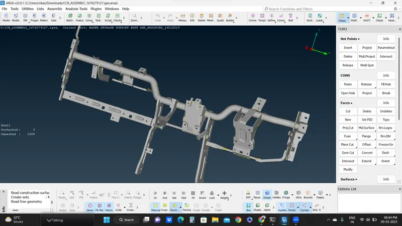
Fig. 01
- Applied check geometry to check the CAD geometry for any errors before proceeding for mid Surfacing (Fig.02).
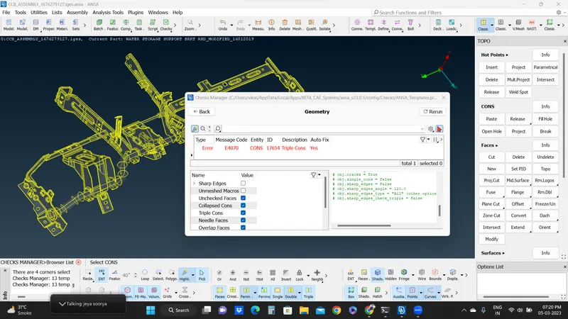
Fig. 02
- Then some errors are auto fixed by selecting fix open while for remaining errors I opened the part of model showing error and deleted the additional face/cons causing error. I used new face option from Faces and added the suitable face. After that I rechecked the check geometry option and it has passed (Fig.03).
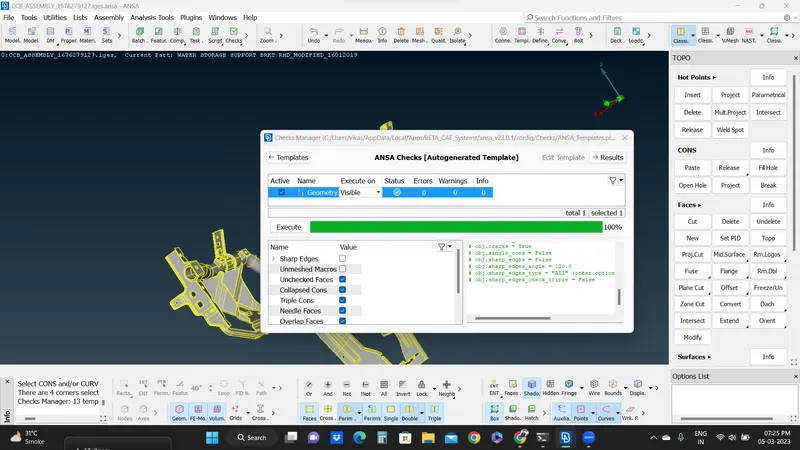
Fig. 03
- To proceed further, I checked the model thickness at various location before applying mid surface and it seem similar to proceed ahead (Fig. 04)
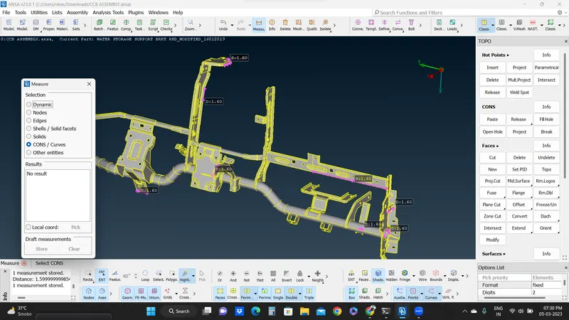
Fig. 04
- Now, I selected the model's parts one by one from properties option and applied Mid Surface from Faces (one part at a time by selecting ON/OFF option in properties).
- After generating mid surface for each part, I visibled all generated mid surface together and applied TOPO (Fig.05).
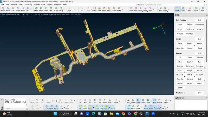
Fig. 05
- With mid surface to proceed with meshing, I have applied perimeter length and macro length as 5 mm from path as Classic Mesh-Perimeters-Length-Perimeters/Macros.
- After assigning perimeter and macro lengths, I applied BEST mesh option from Mesh Generation by selecting the parts of model one by one from properties.
- Applied Quality Criteria as mentioned in the challenge info and it resulted into many off elements (Fig.06).
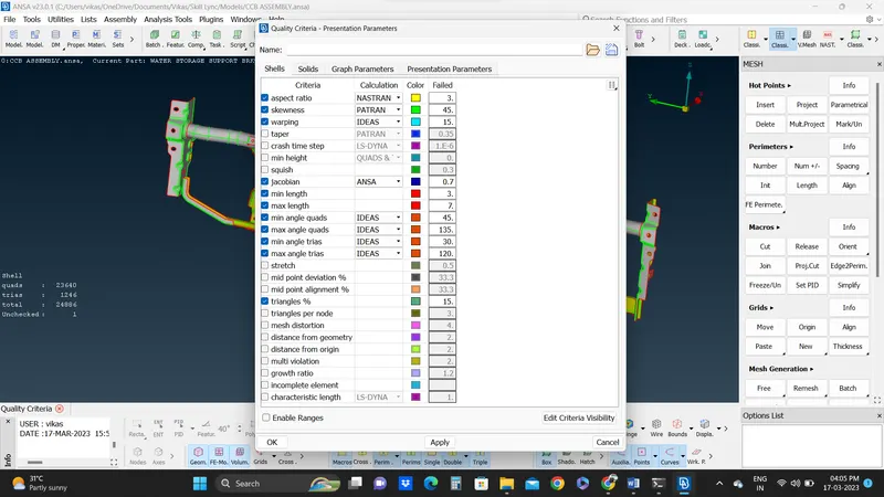
Fig. 06
- To clear the off elements, I have used various options from Shell Mesh and Elements like Split, Swap, Improve, Reconstruct, Fixed Quality, Smooth, etc (Fig.07).
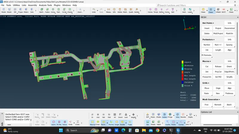
Fig. 07
- After performing all operation the final meshed CCB model is shown in Fig.08
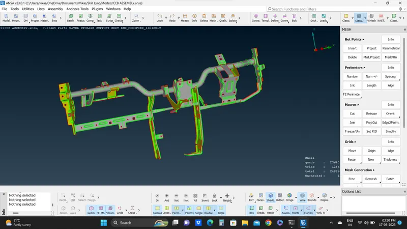
Fig. 08
RESULTS :
After performing all topological and meshing operation obtained the required CCB model with smooth surface and edges. Learned about implementing various tools and option.
FINAL MODEL IMAGE :