Week 8 - Simulation of a backward facing step in OpenFOAM
AIM:- To simulate an incompresible laminar flow through backwards facing step geometry and perform transient simulation.
THEORY
Incompressible flow is when there is no change in densiity .
Mathameticaly incompresisble flow can be expressed as
`∇⋅u=0"> ∇ ⋅ u = 0 R e = (ρ ⋅ v ⋅ L )/μ`
Laminar flow is flow when there is no mixxing in regular fluid motion.It can be visualised by payhlines that do not intersect each other.
In laminar flow the motion of fluid particles is very orderly with particles close tp a solid surface moving in straight lines parallel to rh surface. Laminar is flow regime charachterized by high momentum diffusion and low momentum convection.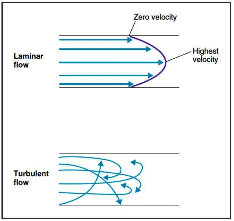
Reynolds number is the parameter to differntiate a flow as laminar or turbulent.
when reynolds number is less than 2000 flow in a pipe is laminar when its greater than 2000 its usually called turbulent.
Technicaly it is ration of inertialforce to viscous force.
Viscous Flow is a type of fluid flow where there is continuous steady motion of particles the motion at fixed points alwyas remain constant also known as steady flow.
The fluid flow in a form of a layer the layer which sticks with the wall has zero velocity which is called no-slip condition and it develops the frictional effect at the wall. Frictional effects are also present between layers of fluid and slower layers tries to slow down the faster layer which can be measured using viscocity.
Mesh Grading
it is ration of size of last cell to the firt cell size.
STEPS & CODE
- First we create folder in which we will be running our simulations.
- Then we need to copy the cavity folder to the run folder so that we can make changes in the blockMeshDict,controldict ,pressure & velocitywe copy because because we are not supoose to make any changes in originals folder in openfoam.
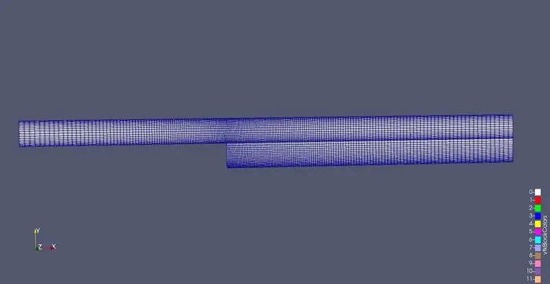
- We make changes in blockmeshdict file where we mention data for all 21 vertices mentioned and mention 5 blocks for elaborating the no. of mesh points in x,y,z directions and grading is done along boundaries.
- then we define boundaries by assigning faces points data to inlet ,outlet,front and back faces and slipwall. by which it will consider which vertices series (that make a face ) is assigned to what roles.
- Then we change pressure and velocity in (0) file change it according to boundary condition in this case pressure is fixed value and velocity is unform with 1.75 towards x axis.
- At inlet there will be fixed value ofhere we should ssign some initial velocity and pressure will be zerogradient At outlet velocity will be zero gradient and pressure wll be fixed value at front and back faces there will be empty pressure and velocity.
- Then we change control dict file where the time and dt value is changed so courant no. is less than 0.5.
- Then we create mesh by block mesh commnd and use icofoam solver to solve and see output using parafoam.
CODE Case-1( no change in grading factor)
Blockmeshdict
FoamFile
{
    format      ascii;
    class       dictionary;
    object      blockMeshDict;
}
// * * * * * * * * * * * * * * * * * * * * * * * * * * * * * * * * * * * * * //

convertToMeters 0.01;

vertices
(
    (0 0 0)
    (8 0 0)
    (8 0.5 0)
    (0 0.5 0)
    (8 1 0)
    (0 1 0)
    (20 1 0)
    (20 0.5 0)
    (20 0 0)
    (20 -1 0)
    (8 -1 0 )
    (0 0 1)
    (8 0 1)
    (8 0.5 1)
    (0 0.5 1)
    (8 1 1)
    (0 1 1)
    (20 1 1)
    (20 0.5 1)
    (20 0 1)
    (20 -1 1)
    (8 -1 1)
);

blocks
(
    hex (0 1 2 3 11 12 13 14) (80 10 1) simpleGrading ( 1 1 1)

    hex (3 2 4 5 14 13 15 16) (80 10 1) simpleGrading (1 1 1)

    hex (2 7 6 4 13 18 17 15) (120 10 1) simpleGrading (1 1 1)

    hex (1 8 7 2 12 19 18 13) (120 10 1) simpleGrading (1 1 1)

    hex (10 9 8 1 21 20 19 12) (120 20 1) simpleGrading (1 1 1)

);

edges

(
);

boundary
(
   inlet
    {
        type patch;
        faces
        (
            (0 11 14 3)
            (3 14 16 5)
        );
    }
    outlet
    {
        type patch;
        faces
        (
            (9 8 19 20)
            (8 7 18 19)
            (7 6 17 18)
        );
    }
    frontAndBack
    {
        type empty;
        faces
        (
            (0 3 2 1)
            (11 12 13 14)
            (3 5 4 2)
            (14 13 15 16)
            (2 4 6 7)
            (13 18 17 15)
            (1 2 7 8)
            (12 19 18 13)
            (10 1 8 9)
            (21 20 19 12)
        );
    }
    noslipwall
    {
        type wall;
        faces
        (
            (4 5 16 15)
            (4 15 17 6)
            (1 12 11 0)
            (9 20 21 10)
            (1 10 21 12)

       );
    }
);
mergePatchPairs
(

);

// ************************************************************************* //
ControlDict
FoamFile
{
    format      ascii;
    class       dictionary;
    location    "system";
    object      controlDict;
}
// * * * * * * * * * * * * * * * * * * * * * * * * * * * * * * * * * * * * * //

application     icoFoam;

startFrom       startTime;

startTime       0;

stopAt          endTime;

endTime         5;

deltaT          2e-4;

writeControl    runTime;

writeInterval   0.5;

purgeWrite      0;

writeFormat     ascii;

writePrecision  6;

writeCompression off;

timeFormat      general;

timePrecision   6;

runTimeModifiable true;
Pressure
FoamFile
{
    format      ascii;
    class       volScalarField;
    object      p;
}
// * * * * * * * * * * * * * * * * * * * * * * * * * * * * * * * * * * * * * //

dimensions      [0 2 -2 0 0 0 0];

internalField   uniform 0;

boundaryField
{
    inlet
    {
        type            zeroGradient;
    }

    outlet
    {
        type            fixedValue;
        value           uniform 0;
    }

    frontAndBack
    {
        type            empty;
    }
    noslipwall
    {
        type            zeroGradient;
    }
}

// ************************************************************************* //
Velocity
FoamFile
{
    format      ascii;
    class       volVectorField;
    object      U;
}
// * * * * * * * * * * * * * * * * * * * * * * * * * * * * * * * * * * * * * //

dimensions      [0 1 -1 0 0 0 0];

internalField   uniform (0 0 0);

boundaryField
{
    inlet
    {
        type            fixedValue;
        value           uniform (1.75 0 0);
    }

    outlet
    {
        type            zeroGradient;
    }

    frontAndBack
    {
        type            empty;
    }
    noslipwall
    {
        type            noSlip;
    }
}

// ************************************************************************* //
Output
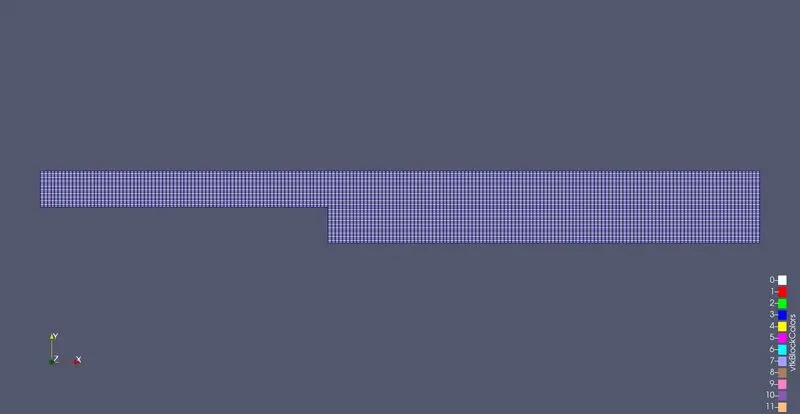
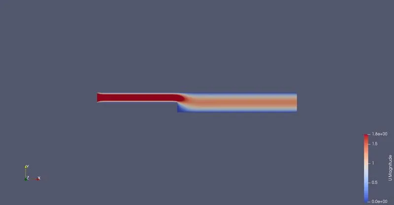
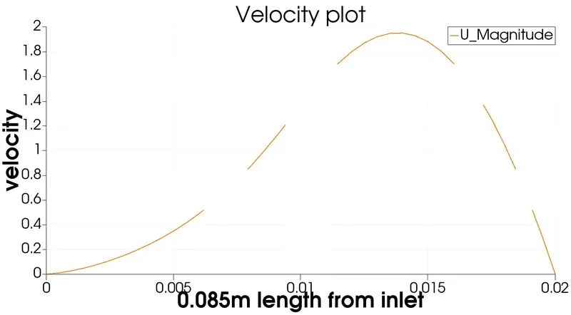
CASE -II (WHERE GRADING FACTOR IS 0.2)
Only change will be in blockmeshdict CODE
FoamFile
{
    format      ascii;
    class       dictionary;
    object      blockMeshDict;
}
// * * * * * * * * * * * * * * * * * * * * * * * * * * * * * * * * * * * * * //

convertToMeters 0.01;

vertices
(
    (0 0 0)
    (8 0 0)
    (8 0.5 0)
    (0 0.5 0)
    (8 1 0)
    (0 1 0)
    (20 1 0)
    (20 0.5 0)
    (20 0 0)
    (20 -1 0)
    (8 -1 0 )
    (0 0 1)
    (8 0 1)
    (8 0.5 1)
    (0 0.5 1)
    (8 1 1)
    (0 1 1)
    (20 1 1)
    (20 0.5 1)
    (20 0 1)
    (20 -1 1)
    (8 -1 1)
);

blocks
(
    hex (0 1 2 3 11 12 13 14) (80 10 1) simpleGrading ( 0.2 5 1)

    hex (3 2 4 5 14 13 15 16) (80 10 1) simpleGrading (.2 .2 1)

    hex (2 7 6 4 13 18 17 15) (120 10 1) simpleGrading (5 0.2 1)

    hex (1 8 7 2 12 19 18 13) (120 10 1) simpleGrading (5 5 1)

    hex (10 9 8 1 21 20 19 12) (120 20 1) simpleGrading (5 5 1)

);

edges

(
);

boundary
(

   inlet
    {
        type patch;
        faces
        (
            (0 11 14 3)
            (3 14 16 5)
        );
    }
    outlet
    {
        type patch;
        faces
        (
            (9 8 19 20)
            (8 7 18 19)
            (7 6 17 18)
        );
    }
    frontAndBack
    {
        type empty;
        faces
        (
            (0 3 2 1)
            (11 12 13 14)
            (3 5 4 2)
            (14 13 15 16)
            (2 4 6 7)
            (13 18 17 15)
            (1 2 7 8)
            (12 19 18 13)
            (10 1 8 9)
            (21 20 19 12)
        );
    }
    noslipwall
    {
        type wall;
        faces
        (
            (4 5 16 15)
            (4 15 17 6)
            (1 12 11 0)
            (9 20 21 10)
            (1 10 21 12)

       );
    }

);
mergePatchPairs
(

);

// ************************************************************************* //
OUTPUT
CONCLUSION
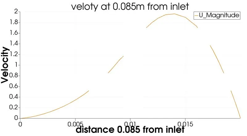
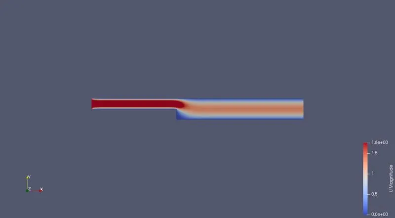
The result is almost same for both grading factor (0.2) and no graded factor only difference is accuracy . The graded project has finer mesh so the result will be smooth and accurate as comaparable to non graded the path for fading velocity is much clear in comparision to non graded factor.