Week 8 - Simulation of a backward facing step in OpenFOAM
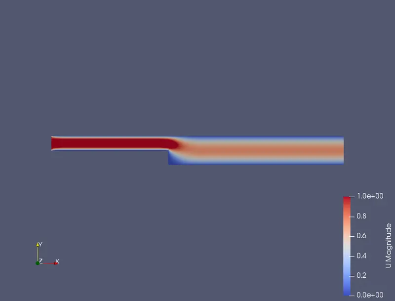
AIM: TO you are going to simulate an incompressible-laminar-viscous flow through the backward facing step geometry.
/*--------------------------------*- C++ -*----------------------------------*\
  =========                 |
  \\      /  F ield         | OpenFOAM: The Open Source CFD Toolbox
   \\    /   O peration     | Website:  https://openfoam.org
    \\  /    A nd           | Version:  9
     \\/     M anipulation  |
\*---------------------------------------------------------------------------*/
FoamFile
{
    format      ascii;
    class       dictionary;
    object      blockMeshDict;
}
// * * * * * * * * * * * * * * * * * * * * * * * * * * * * * * * * * * * * * //

convertToMeters 1;

vertices
(
    (0 0 0)         ///(x,y,z) point 0/vertex0
    (0.08 0 0)    //           point 1/vertex1
    (0.08 0.005 0) //            point2/vertex2
    (0 0.005 0)  //              point3/vertex3
    (0.08 0.01 0)//              point4/vertex4
    (0 0.01 0)  //               point5/vertex5
    (0.20 0.01 0) //             point6/vertex6
    (0.20 0.005 0)//             point7/vertex7
    (0.20 0 0)  //               point8/vertex8
    (0.20 -0.01 0) //            point9/vertex9
    (0.08 -0.01 0)//             point10/vertex10
    (0 0 0.1)     //               point11/vertex11
    (0.08 0 0.1) //                point12/vertex12
    (0.08 0.005 0.1) //            point13/vertex13
    (0 0.005 0.1) //               point14/vertex14
    (0.08 0.01 0.1) //             point15/vertex15
    (0 0.01 0.1)    //             point16/vertex16
    (0.20 0.01 0.1)  //            point17/vertex17
    (0.20 0.005 0.1) //            point18/vertex18
    (0.20 0 0.1)    //             point19/vertex19
    (0.20 -0.01 0.1) //            point20/vertex20
    (0.08 -0.01 0.1) //            point21/vertex21


);

blocks
(
//case 1
      //hex (0 1 2 3 11 12 13 14)  (50 5 1) simpleGrading (1 1 1)
       //hex (3 2 4 5 14 13 15 16)  (50 5 1) simpleGrading (1 1 1)
      // hex (2 7 6 4 13 18 17 15)  (150 5 1) simpleGrading (1 1 1)
       //hex (1 8 7 2 12 19 18 13)  (150 5 1) simpleGrading (1 1 1)
      // hex (10 9 8 1 21 20 19 12) (150 10 1) simpleGrading (1 1 1)


       hex (0 1 2 3 11 12 13 14)  (50 5 1) simpleGrading (1 5 1)
       hex (3 2 4 5 14 13 15 16)  (50 5 1) simpleGrading (1 0.2 1)
       hex (2 7 6 4 13 18 17 15)  (150 5 1) simpleGrading (5 0.2 1)
       hex (1 8 7 2 12 19 18 13)  (150 5 1) simpleGrading (5 5 1)
       hex (10 9 8 1 21 20 19 12) (150 10 1) simpleGrading (5 10 1)
 );
edges
(
);

boundary
(

     inlet
    {
        type patch;
        faces
        (
            (0 11 14 3)
            (3 14 16 5)
        );
    }

     outlet
    {
        type patch;
        faces
        (
            (9 8 19 20)
            (8 7 18 19)
            (7 6 17 18)
        );
    }

    walls
    {
        type wall;
        faces
        (
            (4 5 16 15)
            (6 4 15 17)
            (0 1 12 11)
            (10 9 20 21)
            (10 21 12 1)
        );
    }
    FrontAndBack
    {
     type empty;
     faces
     (
     (3 2 1 0)
     (5 4 2 3)
     (4 6 7 2)
     (2 7 8 1)
     (1 8 9 10)
     (12 13 14 11)
     (13 15 16 14)
     (13 18 17 15)
     (12 19 18 13)
     (21 20 19 12)
     );
     }
);

mergePatchPairs
(
);

// ************************************************************************* //
/*--------------------------------*- C++ -*----------------------------------*\
========= |
\\ / F ield | OpenFOAM: The Open Source CFD Toolbox
\\ / O peration | Website: https://openfoam.org
\\ / A nd | Version: 9
\\/ M anipulation |
\*---------------------------------------------------------------------------*/
FoamFile
{
format ascii;
class dictionary;
location "system";
object controlDict;
}
// * * * * * * * * * * * * * * * * * * * * * * * * * * * * * * * * * * * * * //
application icoFoam;
startFrom startTime;
startTime 0;
stopAt endTime;
endTime 20;
deltaT 1e-2;
writeControl timeStep;
writeInterval 1000;
purgeWrite 0;
writeFormat ascii;
writePrecision 6;
writeCompression off;
timeFormat general;
timePrecision 6;
runTimeModifiable true;
// ************************************************************************* ///*--------------------------------*- C++ -*----------------------------------*\
========= |
\\ / F ield | OpenFOAM: The Open Source CFD Toolbox
\\ / O peration | Website: https://openfoam.org
\\ / A nd | Version: 9
\\/ M anipulation |
\*---------------------------------------------------------------------------*/
FoamFile
{
format ascii;
class volVectorField;
object U;
}
// * * * * * * * * * * * * * * * * * * * * * * * * * * * * * * * * * * * * * //
dimensions [0 1 -1 0 0 0 0];
internalField uniform (0 0 0);
boundaryField
{
inlet
{
type fixedValue;
value uniform (0.03 0 0);
}
outlet
{
type zeroGradient;
}
walls
{
type noSlip;
}
frontAndBack
{
type empty;
}
}
// ************************************************************************* ///*--------------------------------*- C++ -*----------------------------------*\
========= |
\\ / F ield | OpenFOAM: The Open Source CFD Toolbox
\\ / O peration | Website: https://openfoam.org
\\ / A nd | Version: 9
\\/ M anipulation |
\*---------------------------------------------------------------------------*/
FoamFile
{
format ascii;
class volScalarField;
object p;
}
// * * * * * * * * * * * * * * * * * * * * * * * * * * * * * * * * * * * * * //
dimensions [0 2 -2 0 0 0 0];
internalField uniform 0;
boundaryField
{
inlet
{
type zeroGradient;
}
outlet
{
type fixedValue;
value uniform 0;
}
walls
{
type zeroGradient;
}
frontAndBack
{
type empty;
}
}
// ************************************************************************* //
Code Explanation:
- First We are creating Topology of Geometry. In order create a Topology we need Vertices, Hexa Blocks, Boundarys of the Geometry.
- A point is a location in 3-D space, defined by a vector in units of metres (
 ). The points are compiled into a list and each point is referred to by a label, which represents its position in the list, starting from zero.
 - A face is an ordered list of points, where a point is referred to by its label. The ordering of point labels in a face is such that each two neighbouring points are connected by an edge,Faces are compiled into a list and each face is referred to by its label, representing its position in the list. The direction of the face normal vector is defined by the right-hand rule.
- Internal faces, which connect two cells (and it can never be more than two). For each internal face, the ordering of the point labels is such that the face normal points into the cell with the larger label
- Boundary faces, which belong to one cell since they coincide with the boundary of the domain. A boundary face is therefore addressed by one cell(only) and a boundary patch.
CELL:
A cell is a list of faces in arbitrary order. Cells must have the properties listed below.
- The cells must be contiguous,i.e. completely cover the computational domain and must not overlap one another.
- Every cell must be closed geometrically, such that when all face area vectors are oriented to point outwards of the cell, their sum should equal the zero vector to machine accuracy;
- Every cell must be closed topologically such that all the edges in a cell are used by exactly two faces of the cell in question.
BLOCKMESH:
- The mesh is generated from a dictionary file named blockMeshDict located in the system (or constant/polyMesh) directory of a case. blockMesh reads this dictionary, generates the mesh and writes out the mesh data to points and faces, cells and boundary files in the same directory.
- The principle behind blockMesh is to decompose the domain geometry into a set of 1 or more three dimensional, hexahedral blocks.
- Each block of the geometry is defined by 8 vertices, one at each corner of a hexahedron. The vertices are written in a list so that each vertex can be accessed using its label
- Each vertex numbered according to the list,that the first element of the list has label ‘0’
- Each block has a local coordinate system(x1,x2,x3) that must be right-handed. A right-handed set of axes is defined such that to an observer looking down the Oz axis, with" O 'nearest them, the arc from a point on the 'Ox' axis to a point on the 'Oy' axis is in a clockwise sense.
The local coordinate system is defined by the order in which the vertices are presented in the block definition according to:
- the axis origin is the first entry in the block definition, vertex 0 in our example;
- the x1 direction is described by moving from vertex 0 to vertex 1;
- the x2 direction is described by moving from vertex 1 to vertex 2;
- vertices 0, 1, 2, 3 define the plane x3=0;
- vertex 4 is found by moving from vertex 0 in the x3 direction;
- vertices 5,6 and 7 are similarly found by moving in the x3 direction from vertices 1,2 and 3 respectively.
ConvertToMeters :0.001,
- The convertToMeters keyword specifies a scaling factor by which all vertex coordinates in the mesh description are multiplied.
- means that all coordinates are multiplied by 0.001
The vertices: Example:
vertices
(
( 0 0 0 ) // vertex number 0
( 1 0 0.1) // vertex number 1
( 1.1 1 0.1) // vertex number 2
( 0 1 0.1) // vertex number 3
(-0.1 -0.1 1 ) // vertex number 4
( 1.3 0 1.2) // vertex number 5
( 1.4 1.1 1.3) // vertex number 6
( 0 1 1.1) // vertex number 7
)
The edges:
- Each edge joining 2 vertex points is assumed to be straight by default. However any edge may be specified to be curved by entries in a list named edges.
-
Each entry for a curved edge begins with a keyword specifying the type of curve from those listed below.
- arc: a circular arc with a single interpolation point or angle + axis (see below).
- spline: spline curve using a list of interpolation points
- polyLine: a set of lines with list of interpolation points
- BSpline: a B-spline curve with list of interpolation points
- line: a straight line, the default which requires no edge specification
- edges
(
arc 1 5 (1.1 0.0 0.5)
);
The blocks:
The block definitions are contained in a list named blocks
blocks
(
hex (0 1 2 3 4 5 6 7) // vertex numbers
(10 10 10) // numbers of cells in each direction
simpleGrading (1 2 3) // cell expansion ratios
);
- The first entry is the shape identifier of the block,The shape is always hex since the blocks are always hexahedra.
- The second entry gives the number of cells in each of the x1 x2 and x3 directions for that block.
- The third entry gives the cell expansion ratios for each direction in the block,The expansion ratio enables the mesh to be graded, or refined, in specified directions. The ratio is that of the width of the end cell
 along one edge of a block to the width of the start cell
  along that edge, as shown
 - Expansion ratio===/.
- The simple grading option specifies uniform expansions in the local x1 x2 and x3 directions respectively with only 3 expansion ratios, e.g.
simpleGrading (1 2 3).
POLYMESH:
- A polygonal mesh is a collection of vertices and their connectivity that models the surface a polyhedral object.
The constant directory contains a full description of the case polyMesh in a subdirectory polyMesh. The polyMesh description is based around faces and, as already discussed, internal faces connect 2 cells and boundary faces address a cell and a boundary patch. Each face is therefore assigned an ‘owner’ cell and ‘neighbour’ cell so that the connectivity across a given face can simply be described by the owner and neighbour cell labels. In the case of boundaries, the connected cell is the owner and the neighbour is assigned the label ‘1’.
- points,
- a list of vectors describing the cell vertices, where the first vector in the list represents vertex 0, the second vector represents vertex 1, etc.
- faces,
- a list of faces, each face being a list of indices to vertices in the points list, where again, the first entry in the list represents face 0, etc.
- owner,
- a list of owner cell labels, the index of entry relating directly to the index of the face, so that the first entry in the list is the owner label for face 0, the second entry is the owner label for face 1, etc;
- neighbour,
- a list of neighbour cell labels
- boundary,
- a list of patches, containing a dictionary entry for each patch, declared using the patch name.