Week 8 - Simulation of a backward facing step in OpenFOAM
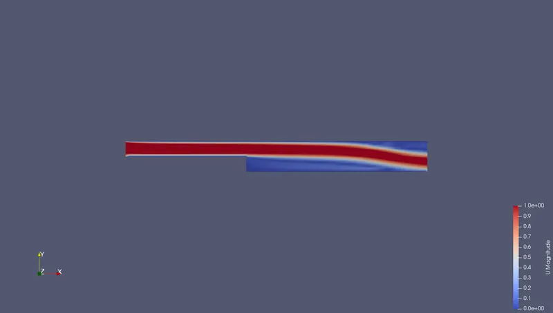
Aim of this project is to simulate an incompressible-laminar-viscous flow through the backward facing step geometry (transient simluation).
Intorduction: After the simulation, velocity and pressure profiles for different gradinf factors is acheived. The geometry of the given backward facing step are as given below,
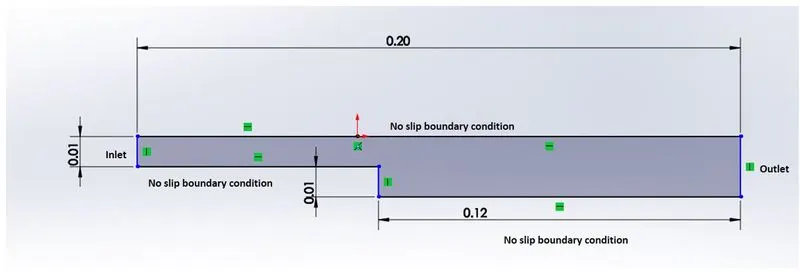
Type of flow: Incompressible, laminar, viscous
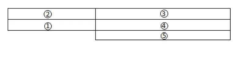
Blockmesh specification: No. of blocks :5
Representation is as below,
The naming in 3D of the blocks is as below,
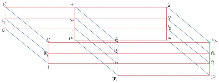
Meshing specificaton:
- Number of cells along the x direction (longer dimension) = 200
- Number of cells along the longer y direction = 20;
Desired output:
step 1: Run the simulation without grading factor.
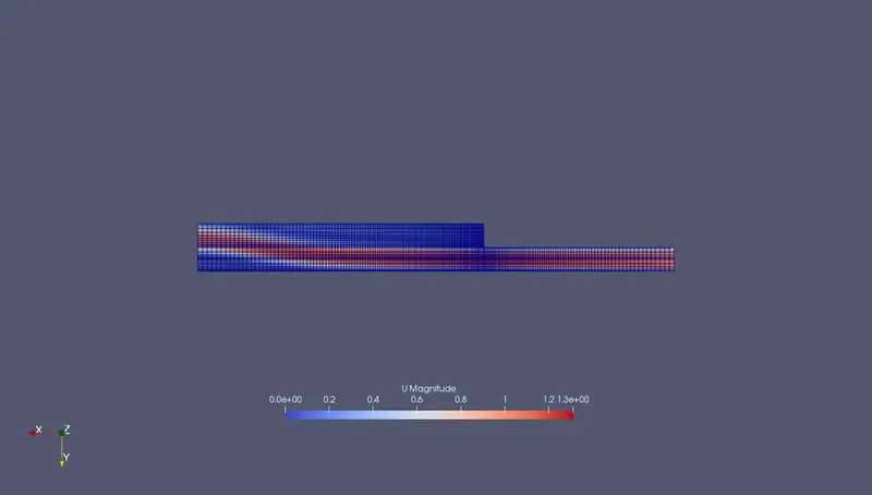
step 2: Run the simulation with grading factor of 0.2.
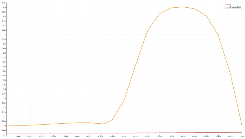
step 3: Measure the veloicty at 0.085m from inlet of the step geometry with line plot.
step 4: Comparison of velocty profiles with and without grading factor.
Explanation of the reference case files obtained from opemFoam tutorials -
- tut - gong to tutorial folder
- incompressible - icoFoam - cavity - Selecting icoFoam solver which solves incompressible laminar Navier Stokes equations (Continuity and momentum )using PISO algorithm.
- cavity - Selecting cavity folder
- cp -r cavity/ $FOAM_RUN/cavity_t - copying cavity folder into run folder feom where the simulations run.
- Then go to run folder
- cd cavity/ -Then go to cavity_t folder
- cd system -Going to system folder
- gedit blockMeshDict - we get C++ file for geometry
- Now we have to edit here in file ac per given dimensions.
- Then go to folder cavity in run folder and blockMesh will do the meshing according to specification
- Then modify the pressure , velocity from 0 folder in system , controlDcit folder (for dt and time of simulation)
- Specify inlet and outlet as patch type because there is flow throght them, while set upper and lower walls as wall type, as we are ignoring front and back, type is empty.
- Then typing icoFoam in run cavity folder will run the simulation.
- Then open paraFoam, and select apply , surface with edges to see meshing. Then playing the simulation will start the simulation animation.
- Then post process the case by line over plot option.
OpemFoam code for creating Geometry using blockmesh :
/*--------------------------------*- C++ -*----------------------------------*\
  =========                 |
  \\      /  F ield         | OpenFOAM: The Open Source CFD Toolbox
   \\    /   O peration     | Website:  https://openfoam.org
    \\  /    A nd           | Version:  8
     \\/     M anipulation  |
\*---------------------------------------------------------------------------*/
FoamFile
{
    version     2.0;
    format      ascii;
    class       dictionary;
    object      blockMeshDict;
}
// * * * * * * * * * * * * * * * * * * * * * * * * * * * * * * * * * * * * * //

convertToMeters 1;

vertices
(
    (0 0 0) //0
    (0.08 0 0) //1
    (0.08 0.005 0) //2
    (0 0.005 0) //3
    (0.08 0.01 0) //4
    (0 0.01 0) //5
    (0.2 0.01 0) //6
    (0.2 0.005 0) //7
    (0.2 0 0) //8
    (0.2 -0.01 0) //9
    (0.08 -0.01 0) //10

    (0 0 0.001) //11
    (0.08 0 0.001) //12
    (0.08 0.005 0.001) //13
    (0 0.005 0.001) //14
    (0.08 0.01 0.001) //15
    (0 0.01 0.001) //16
    (0.2 0.01 0.001) //17
    (0.2 0.005 0.001) //18
    (0.2 0 0.001) //19
    (0.2 -0.01 0.001) //20
    (0.08 -0.01 0.001) //21
);

blocks
(
    hex (0 1 2 3 11 12 13 14) (80 5 1) simpleGrading (0.2 0.2 1)
    hex (3 2 4 5 14 13 15 16) (80 5 1) simpleGrading (0.2 0.2 1)
    hex (2 7 6 4 13 18 17 15) (120 5 1) simpleGrading (5 0.2 1)
    hex (1 8 7 2 12 19 18 13) (120 5 1) simpleGrading (5 0.2 1)
    hex (10 9 8 1 21 20 19 12) (120 10 1) simpleGrading (5 0.2 1)
);

edges
(
);

boundary
(
    inlet
    {
        type patch;
        faces
        (
            (0 11 14 3)
            (3 14 16 5)
        );
    }
    outlet
    {
        type patch;
        faces
        (
            (8 19 20 9)
            (7 18 19 8)
            (6 17 18 7)

        );
    }
    upperwalls
    {
        type wall;
        faces
        (
            (5 16 15 4)
            (4 15 17 6)
        );
    }
    lowerwalls
    {
    	type walls;
    	faces
    	(
    		(12 11 0 1)
    		(20 21 10 9)
    		(10 21 12 1)
    	);
    	}
    frontAndBack
    {
    	type empty;
    	faces
    	(
    		(11 12 13 14)
    		(14 13 15 16)
    		(13 18 17 15)
    		(12 19 18 13)
    		(21 20 19 12)
    		(3 2 1 0)
    		(5 4 2 3)
    		(4 6 7 2)
    		(2 7 8 1)
    		(1 8 9 10)
    	);
    	}
);

mergePatchPairs
(
);

// ************************************************************************* //
Time step specification in controlDict
dt = 0.005 sec
time = 5 sec
/*--------------------------------*- C++ -*----------------------------------*\
  =========                 |
  \\      /  F ield         | OpenFOAM: The Open Source CFD Toolbox
   \\    /   O peration     | Website:  https://openfoam.org
    \\  /    A nd           | Version:  8
     \\/     M anipulation  |
\*---------------------------------------------------------------------------*/
FoamFile
{
    version     2.0;
    format      ascii;
    class       dictionary;
    location    "system";
    object      controlDict;
}
// * * * * * * * * * * * * * * * * * * * * * * * * * * * * * * * * * * * * * //

application     icoFoam;

startFrom       startTime;

startTime       0;

stopAt          endTime;

endTime         5;

deltaT          0.0005;

writeControl    timeStep;

writeInterval   20;

purgeWrite      0;

writeFormat     ascii;

writePrecision  6;

writeCompression off;

timeFormat      general;

timePrecision   6;

runTimeModifiable true;


// ************************************************************************* //
Boundary conditions for pressure and velocity from o folder in cavity
/*--------------------------------*- C++ -*----------------------------------*\
  =========                 |
  \\      /  F ield         | OpenFOAM: The Open Source CFD Toolbox
   \\    /   O peration     | Website:  https://openfoam.org
    \\  /    A nd           | Version:  8
     \\/     M anipulation  |
\*---------------------------------------------------------------------------*/
FoamFile
{
    version     2.0;
    format      ascii;
    class       volScalarField;
    object      p;
}
// * * * * * * * * * * * * * * * * * * * * * * * * * * * * * * * * * * * * * //

dimensions      [0 2 -2 0 0 0 0];

internalField   uniform 0;

boundaryField
{
    inlet
    {
        type            zeroGradient;
    }

    outlet
    {
    	type		  fixedValue;
        value            uniform 0;
    }

    frontAndBack
    {
        type            empty;
    }

    upperwalls
    {
    	type		zeroGradient;
    }

    lowerwalls
    {
    	type		zeroGradient;
    }
}

// ************************************************************************* //
We are setting pressure outlet and velocity inlet boundary conditions.
/*--------------------------------*- C++ -*----------------------------------*\
  =========                 |
  \\      /  F ield         | OpenFOAM: The Open Source CFD Toolbox
   \\    /   O peration     | Website:  https://openfoam.org
    \\  /    A nd           | Version:  8
     \\/     M anipulation  |
\*---------------------------------------------------------------------------*/
FoamFile
{
    version     2.0;
    format      ascii;
    class       volVectorField;
    object      U;
}
// * * * * * * * * * * * * * * * * * * * * * * * * * * * * * * * * * * * * * //

dimensions      [0 1 -1 0 0 0 0];

internalField   uniform (0 0 0);

boundaryField
{
    inlet
    {
        type            fixedValue;
        value           uniform (1 0 0);
    }

    outlet
    {
        type            zeroGradient;
    }

    frontAndBack
    {
        type            empty;
    }

    upperwalls
    {
    	type		noSlip;
    }

    lowerwalls
    {
    	type		noSlip;
    }


}

// ************************************************************************* //
The velocity in x axis is set as 1 m/s.
Then setting up the transport properties
/*--------------------------------*- C++ -*----------------------------------*\
  =========                 |
  \\      /  F ield         | OpenFOAM: The Open Source CFD Toolbox
   \\    /   O peration     | Website:  https://openfoam.org
    \\  /    A nd           | Version:  8
     \\/     M anipulation  |
\*---------------------------------------------------------------------------*/
FoamFile
{
    version     2.0;
    format      ascii;
    class       dictionary;
    location    "constant";
    object      transportProperties;
}
// * * * * * * * * * * * * * * * * * * * * * * * * * * * * * * * * * * * * * //

nu              [0 2 -1 0 0 0 0] 1.48e-5;


// ************************************************************************* //
Kinematic viscosity of fluid (Air) is :1.48 e-5 m^2/s .
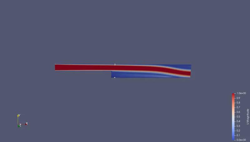
Now, case 1) grading factor = 1
Results: Mesh
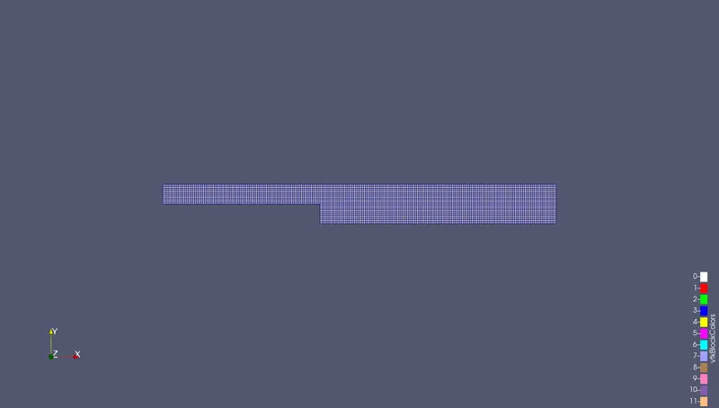
Analysis:
Velocity profile at 0.085m from inlet of step:
case 2) Grading Factor = 0.2
Meshing
Graph for velocity profile
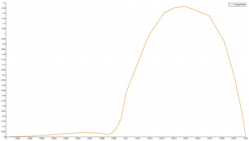
Analysis
Conclusions :
- Mesh grading factor is used to have more number of grids near walls.
- From the velocity graphs its noted that velocity profile gets smoother near the walls. In the Gradinf factor 0.2, its more smooth than no grading factor.
- In 0.2 factor, velocity profile has sharp edges in the region other than walls.