Week 8 - Simulating Cyclone separator with Discrete Phase Modelling
Aim: To perform analysis on cyclone seperator and calculate the seperation efficiency and pressure drop.
Objective:
- To write a few words about any four empirical models used to calculate the cyclone separator efficiency.
- To perform an analysis on a given cyclone separator model by varying the particle diameter from 1 μm to 5 μm and calculate the separation efficiency in each case. Discuss the results. [Use both the velocity's as 3m/sec.]
- To perform an analysis on a given cyclone separator model by varying the particle velocity from 1 m/sec to 5 m/sec and calculate the separation efficiency and pressure drop in each case. Discuss the results. [Use particle diameter size as 5 μm for all cases & keep flow velocity same as particle velocity
Theory:
- What is a cyclone seperator?
Cyclone seperator are devices that are used to remove particulate matter from flue gases by using the concept of inertia. Cyclone seperators are also called as precleaners as they remove larger particles which tend to be more abrasive in nature. By removing these larger particles, finer filterations methods are able to work efficiently.
- How does a cyclone seperator work?
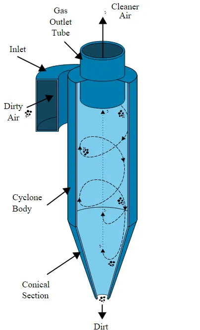
Cyclone seperator works like a centrifuge but with a continous supply of flue gases. From the inlet of the cyclone seperator, dirty flue gases enter the seperators chamber. The shape of the chamber causes the flow of gas to take place in a spiral manner i.e., like a tornado.
Particles with very low interia within the gas get affected by the vortex and travel upward whereas the heavier particles travel downward and get settled in a chamber built to extract larger particles from the flue gases.
Cyclone seperators are mostly used to seperate particles of the dimension 10 micrometer but there are seperators which can seperate particles as low as 2.5 micrometer.
However, if very large particle size like 200 micrometer is used, it would be very in-efficient to filter it.
- Efficiency of a cyclone seperator:
The efficiency of the cyclone seperator depends upon the amount of particulate matter present within the flue gas. If the amount of particles present within the flue gases are small, the efficiency of the cyclone seperator decreases.
In general, one can expect 50-99% efficient removal of particulate matter.
- What is Discrete phase modelling (DPM)?
Discrete phase modelling or DPM is a subsection of multiphase flow. DPM is used to track particle moment using a lagrangian view rather than a Eularian view.
The difference between the Lagrangian and the Eulerian view is that fluid behavior in the Lagrangian view is examined based on particle tracking of a particulate flow, whereas fluid behavior is considered in the Eulerian view based on the assumption of a finite volume element in the fluid flow path.
- What are the four different types of emperical model used to calculate cyclone seperator efficiency? Explain one.
The different models used to calculate cyclone efficiency are:
- Iozia and leith model
- Li and Wang model
- Koch and litch model
- Lapple model
Iozia and leith model: This model is based of force balance within the seperator. The model assumes that a particle carried by the vortex endures the influence of two forces: a centrifugal force, Z and a flow resistance, W .
The collection efficiency of the a particle diameter(d_pi) can be calculated using the given formula.
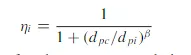
Here, beta is an expression for slope.
Pre-processing:
- First, we will import the geometry of cyclone seperator into spaceclaim to extract the fluid volume required for our analysis.
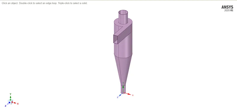
- We will use the volume extract feature to extract inner volume of fluid as we only need to study the internal volume.
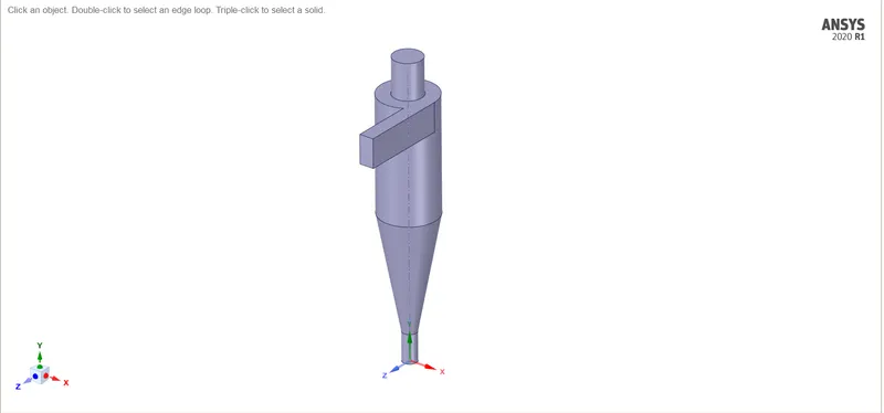
- Before we close spaceclaim, we will make sure to supress the thickness by enabling "supress for physics".
- We will now open the meshing window and name the inlet and outlets of the cyclone seperator.
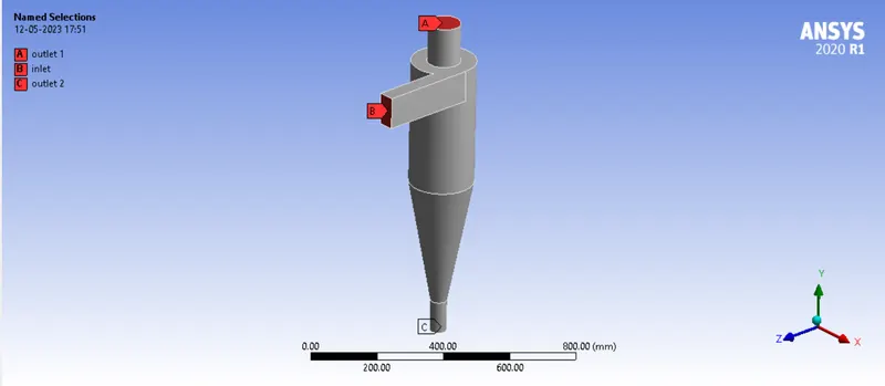
- After this, we will generate a mesh of 10 mm. It creates about 1 lakh eleme
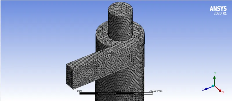
- After our mesh has been completed, we will move to the fluent section and perform the analysis.
Analysis:
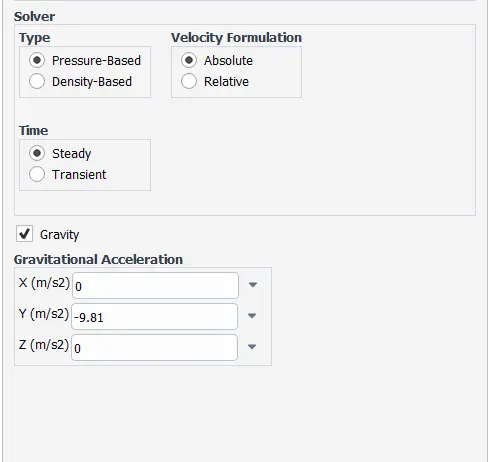
- Within the solver settings, we will set the solver type to pressure based and steady state. We need to enable gravity as well. The axis for gravity is y.
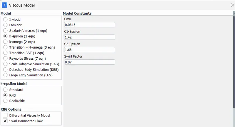
- We will set the viscous model to be K-epsilon RNG model and select a swirl dominated flow. This model is very suitable to track particles in a swirling flow.
- After this, we will enable the Discrete phase modelling. Within the settings, I enabled the "interaction with continous flow" as it creates interactions between the continous phase and discrete phase.
- The maximum number of time steps given is 50,000. The maximum number of time steps indicate the maximum number of steps solver uses to track a particular particle. During swirl flows, there are possibilities that particles can get trapped within a circulation zone and remain trapped there. According to our understanding of the problem we can reduce and increase the number of time steps.
BASE ANALYSIS:
- Within DPM, we will use injection tab to inject particles from the inlet.
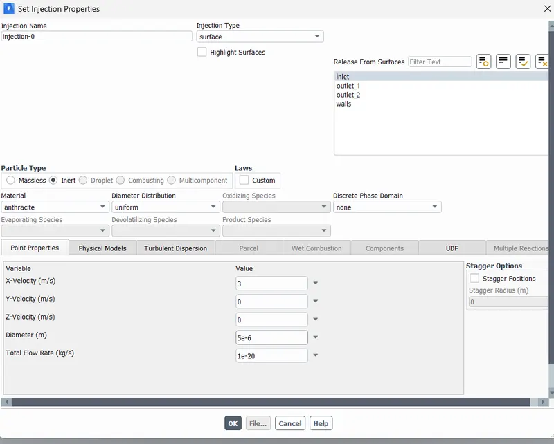
- The particle we are going to use is "Anthracite". We will select the injection type to be "Surface" and use inlet as the injection surface from where particles will be released.
- A velocity of 3 m/s is given to the particles. The diameter of the particle is set to be 5e-6.
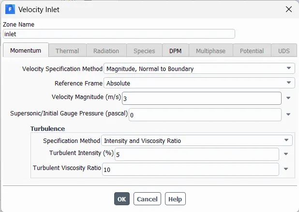
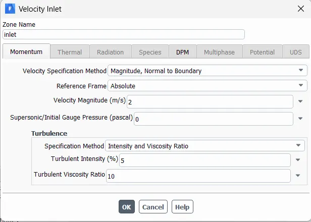
- With this, we can move to the boundary conditions and set the inlet velocity.
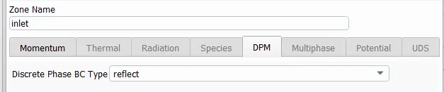
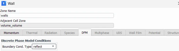
- Inlet and walls: Reflect
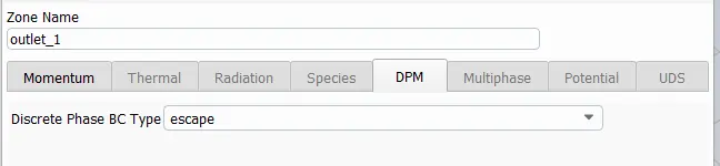
- Outlet (Top): Escape
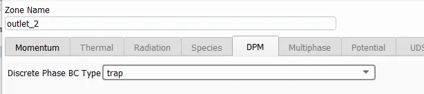
- Output (Bottom/dustbin): Trap
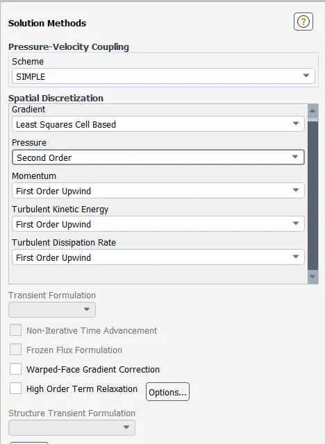
- After that we will set the solution methods as shown below
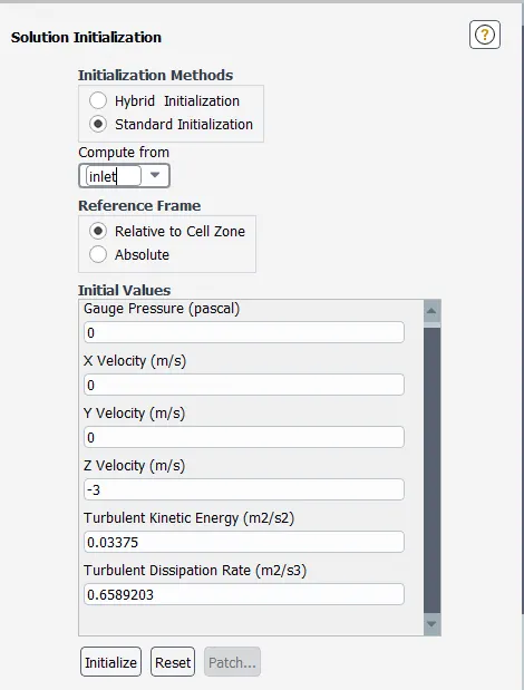
- We will use standard initialization and select "inlet" as the region to compute from.
- After this, we will run 300 iterations to see whether the base setup provided is appropriate or not.
- From the image given below, we can see that the particles are being trapped within the geometry as we set the 2nd outlet to trap particles.

- The particle seperation efficiency = 86/124 = 69.35%.
Results and conclusion (Base):
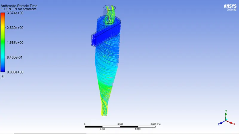
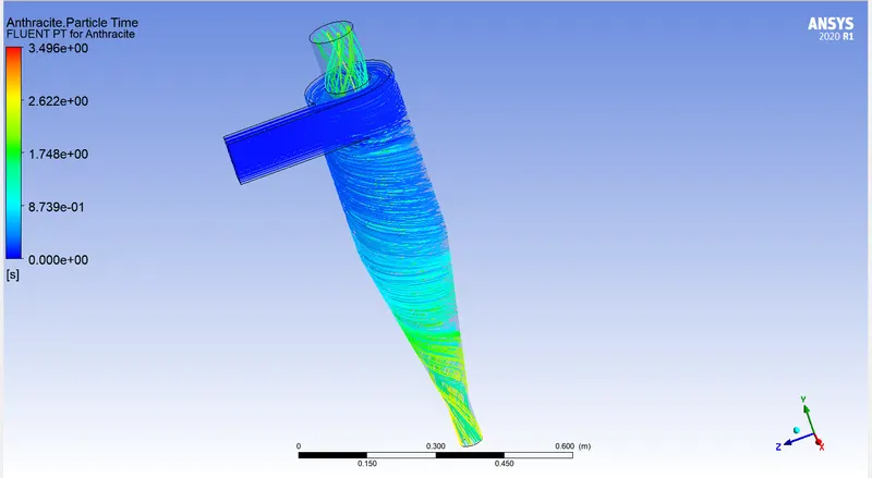
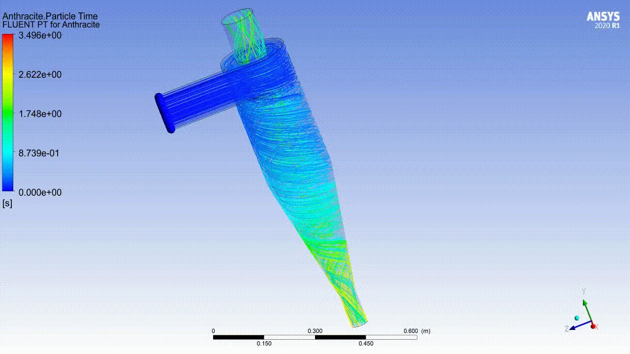
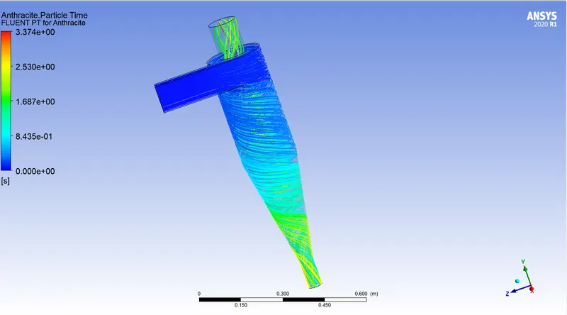
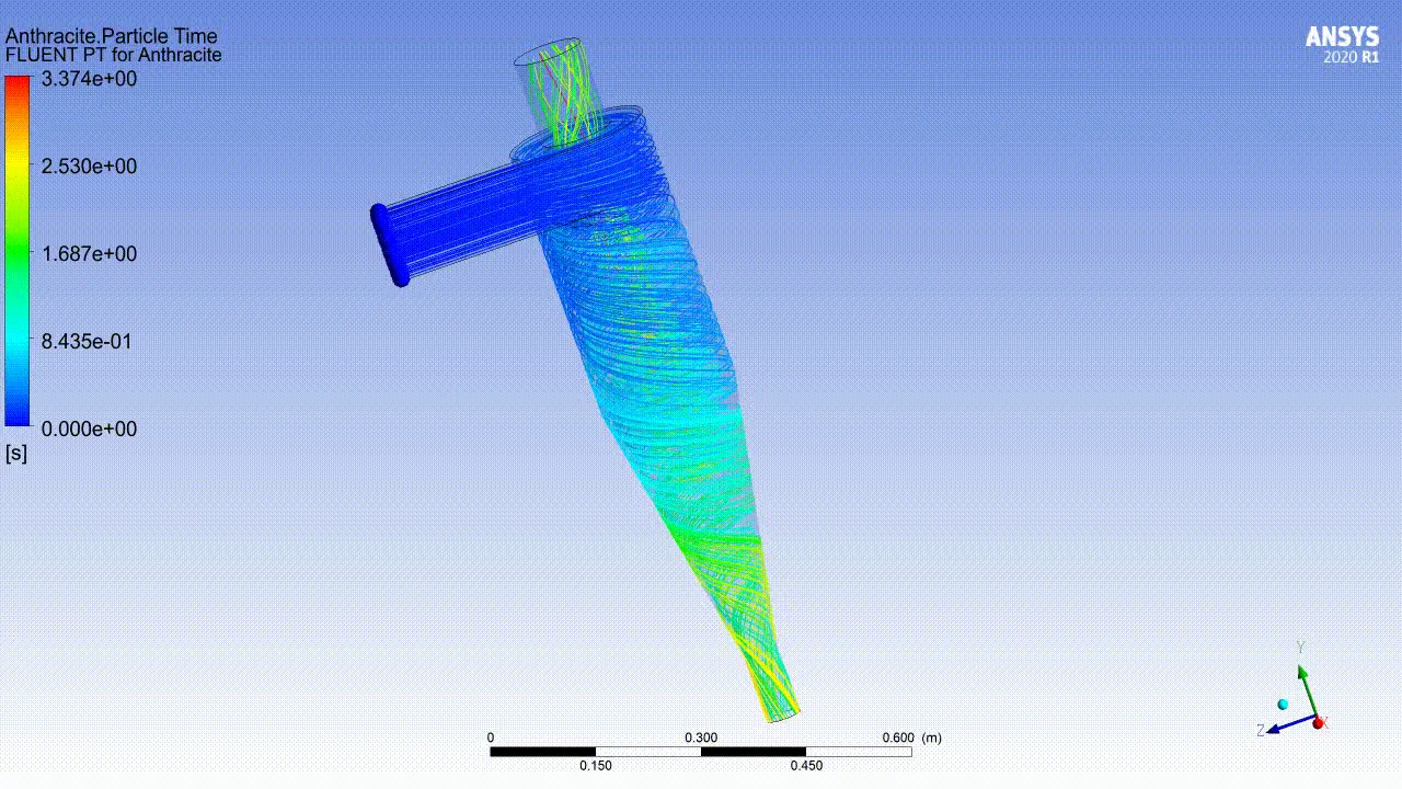
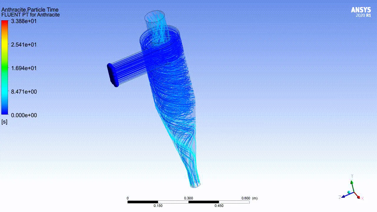
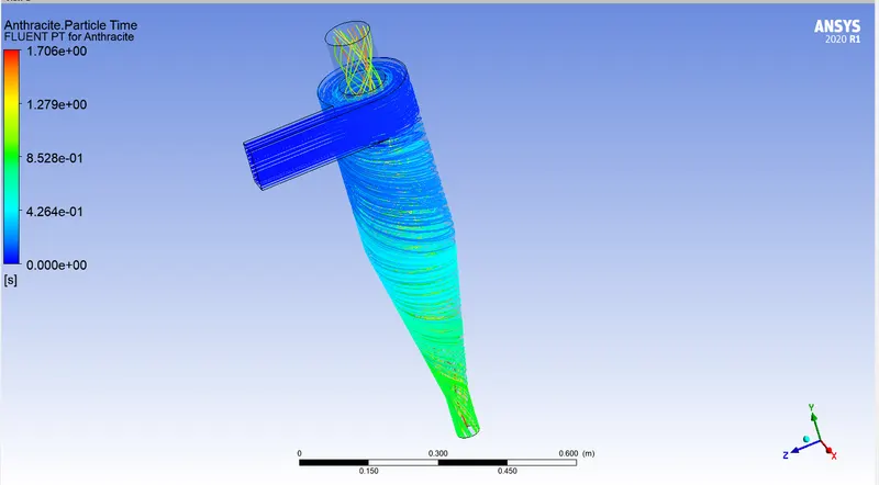
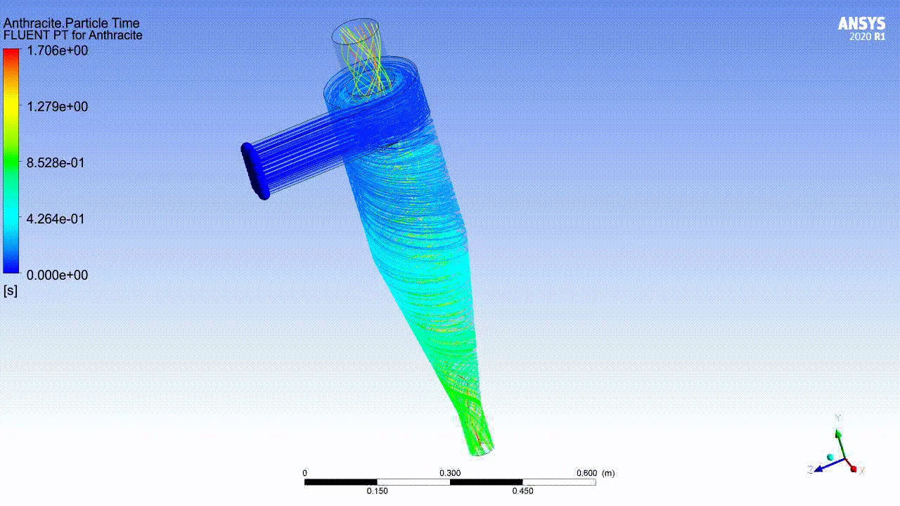
- The contour above shows the particle time i.e., the amount of time spent by particle at a particular location.
- The result show that the particles are flowing very well which is a very good sign. We can go forward and run for different cases.
CASE 2: To perform an analysis on a given cyclone separator model by varying the particle diameter from 1 μm to 5 μm and calculate the separation efficiency in each case. Discuss the results. [Use both the velocity's as 3m/sec.]
- The setup for the problem is almost same. We only need to change the particle diameter from 1 micrometer to 5 micrometer. Velocity is to be kept at 3m/s.
1. Particle Size: 1 micrometer
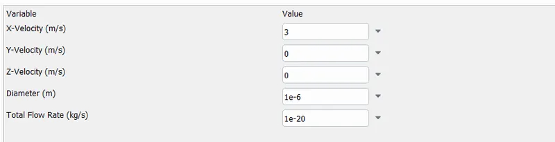
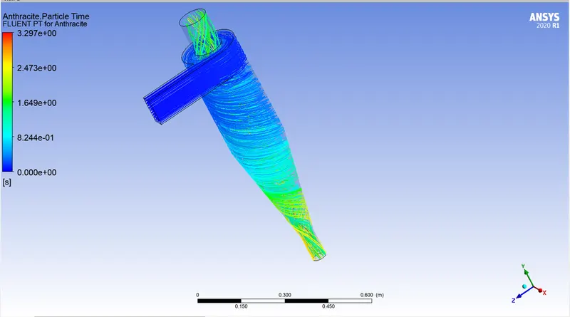
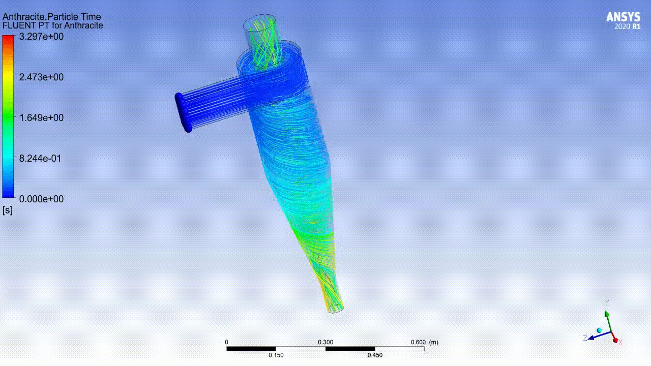
- With the following changes made, we will run the analysis for 300 iterations. We will export the particle history data to be used to in CFD Post.

- Seperation efficiency: 75/124 = 60.48%
Results:
- Particle time with animation:
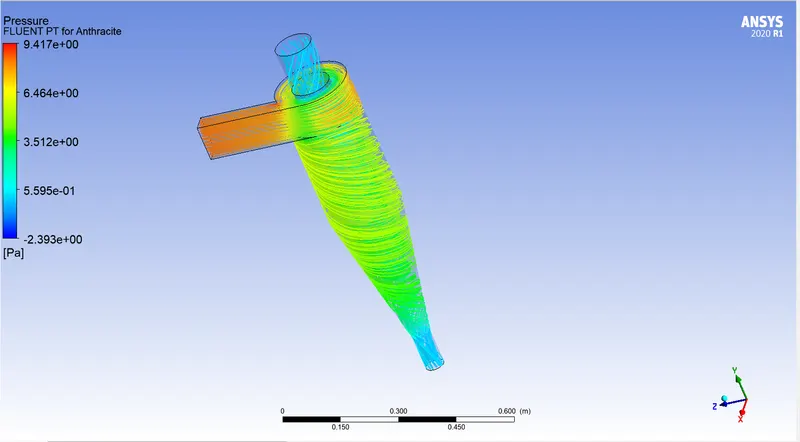
- Pressure:
2. Particle Size: 2 micrometer
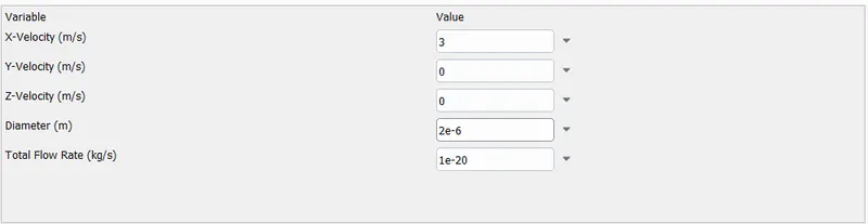
- We will run the analysis for 300 iterations.

Seperation efficiency: 76/124 = 61.29%
RESULTS:
- Anthracite particle time:
- Pressure:
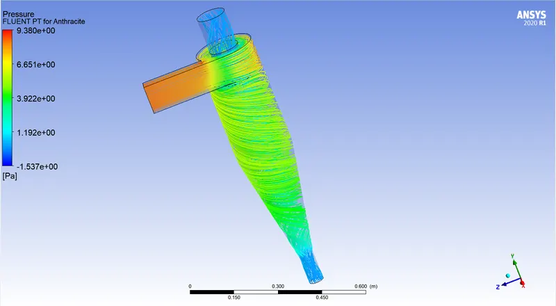
3. Particle Size: 3 micrometer
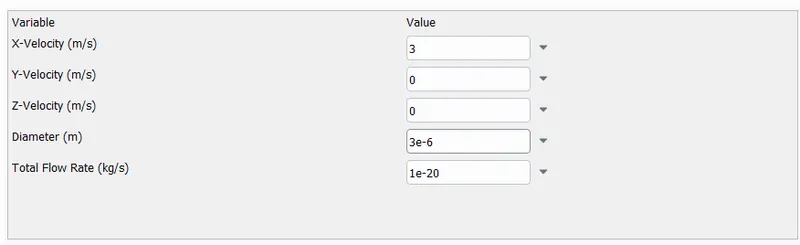
- We will run the calculation for 300 iterations.

Seperation efficiency = 79/124 = 63.70%
RESULTS:
- Anthracite particle time:
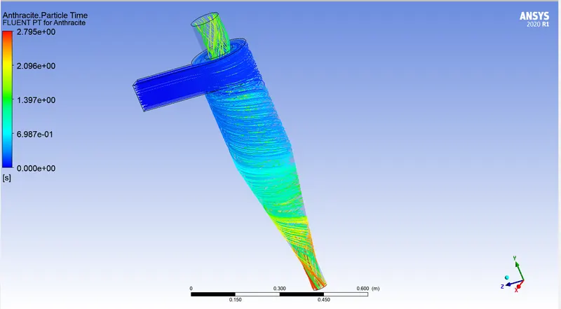
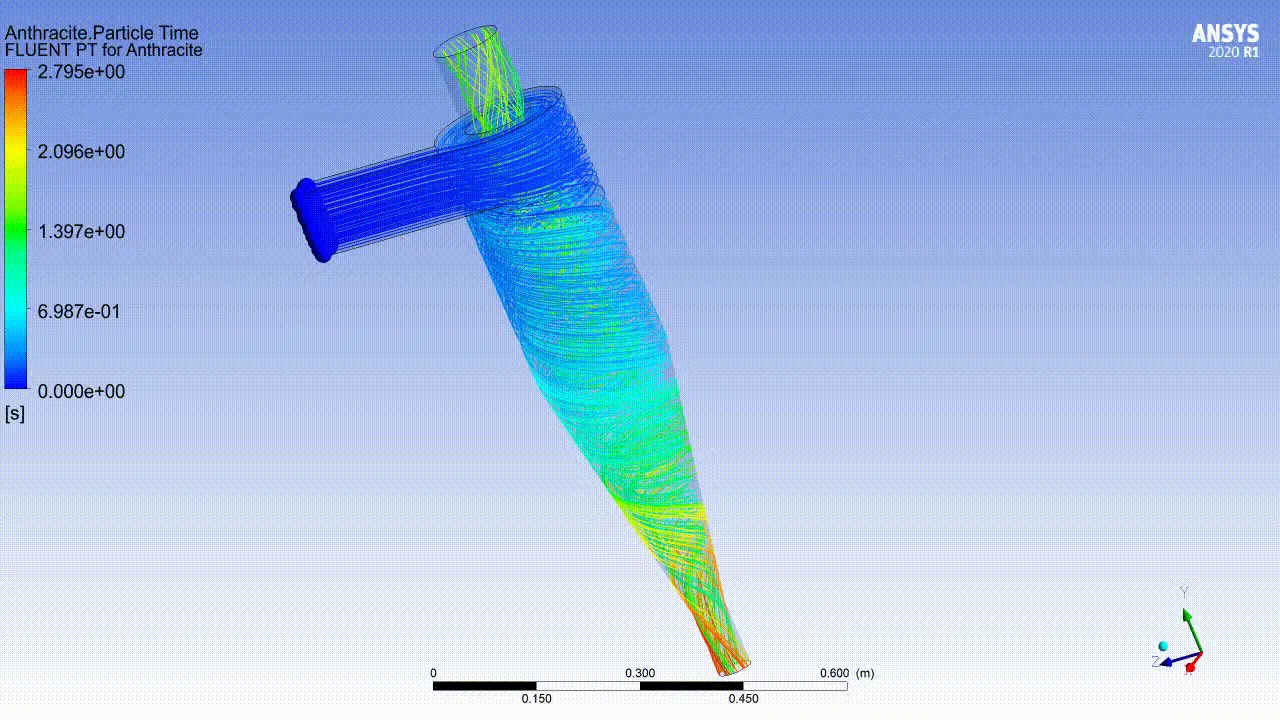
- Pressure:
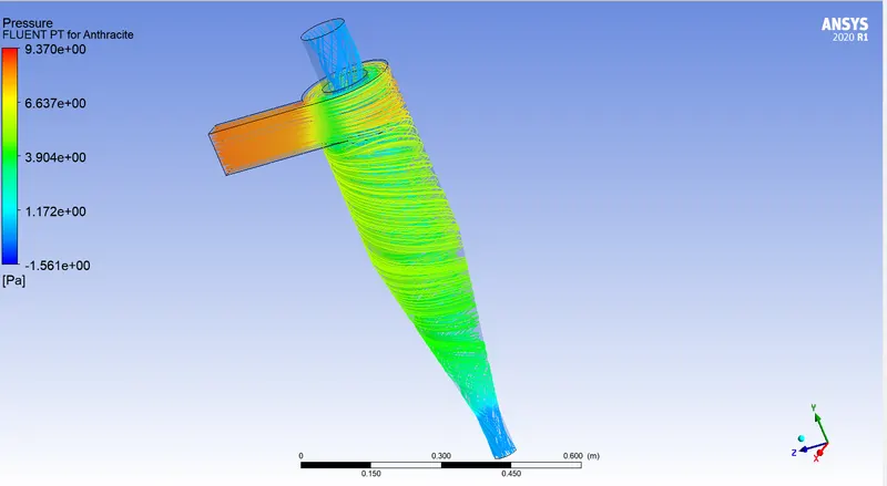
4. Particle Size: 4 micrometer
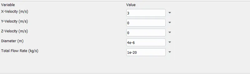
- We will run it for 300 iterations.

Seperation efficiency: 80/124 = 64.51%
RESULTS:
- Anthracite particle time:
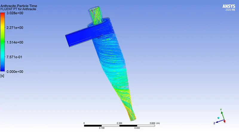
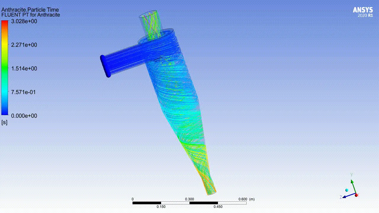
- Pressure:
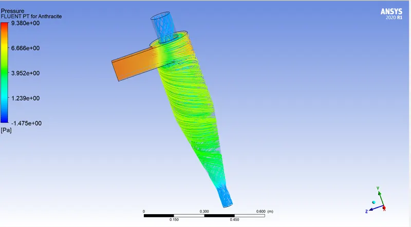
5. Particle Size: 5 micrometer
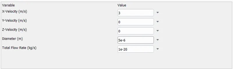
- We will run the calculations for 300 iterations.

Seperation efficiency: 86/124 = 69.35%.
RESULTS:
- Anthracite particle time:
- Pressure:
RESULTS (CASE 2):
| Sr No. | Particle diameter | Seperation efficency | Escaped particles |
| 1 | 1 micrometer | 60.48 % | 48 |
| 2 | 2 micrometer | 61.29 % | 47 |
| 3 | 3 micrometer | 63.70 % | 45 |
| 4 | 4 micrometer | 64.51 % | 44 |
| 5 | 5 micrometer | 69.35 % | 38 |
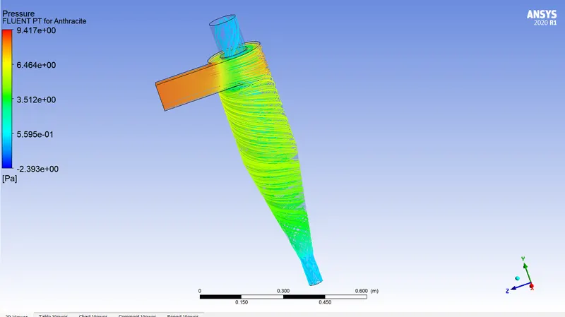
- As particle diameter keeps on increasing from 1 micrometer to 5 micrometer the seperation efficiency increases. This is because the particles with a lesser diameter will have lesser weight. Particles with lighter weight are easily carried upwards with the vortex in the central part of the seperator.
- As observed from the results the particles escaping from outlet 1 is decreasing with increase in particle size.
CASE 3: To perform an analysis on a given cyclone separator model by varying the particle velocity from 1 m/sec to 5 m/sec and calculate the separation efficiency and pressure drop in each case. Discuss the results. [Use particle diameter size as 5 μm for all cases & keep flow velocity same as particle velocity]
In this case, the particle velocity has to be varied from 1 m/s to 5 m/s. Particle diameter will be kept at 5 micrometer.
1. Particle velocity = 1 m/s
- To set the particle velocity, we need to change the velocity of particle within the DPM settings and also at the boundary conditions.
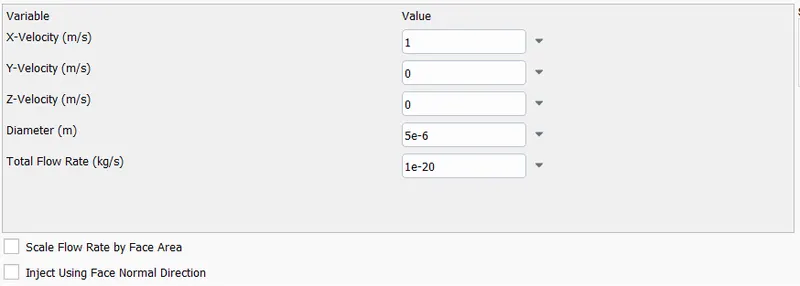
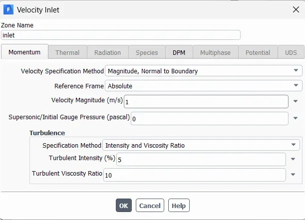
- We will perform the calculation for 300 iterations.

Seperation efficiency: 57/124 = 45.96 %
RESULTS:
- Anthracite particle time:
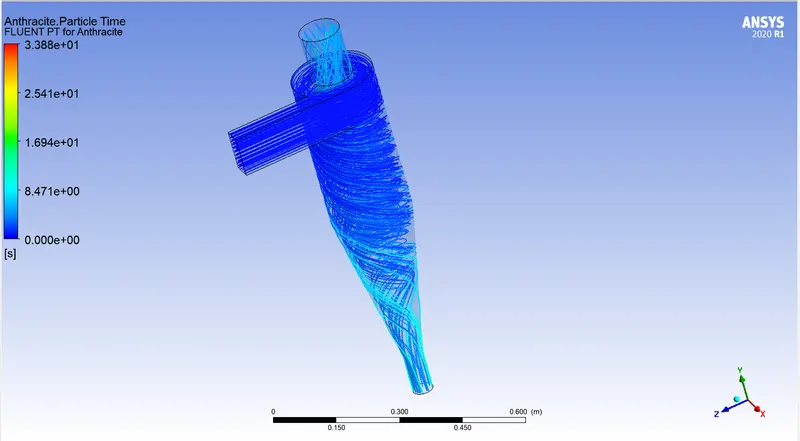
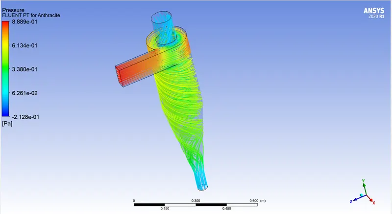
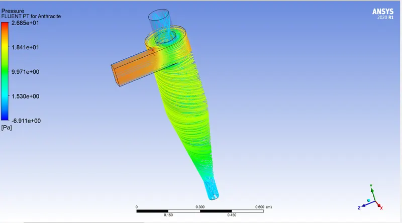
- Pressure:
2. Particle velocity = 2m/s
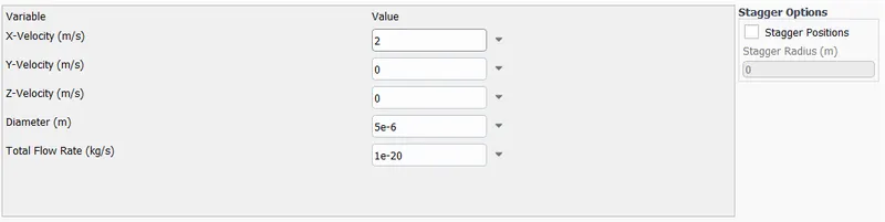
- We will run the calculation for 300 iterations.

Seperation efficiency: 76/124 = 61.29%
RESULTS:
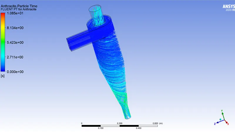
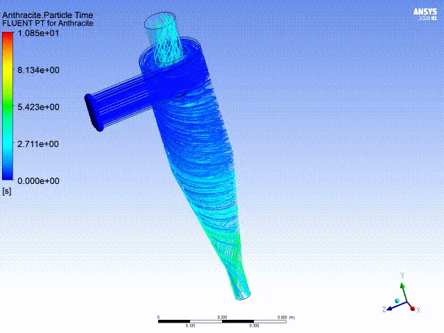
- Anthracite particle time:
- Pressure:
3. Particle velocity = 4 m/s
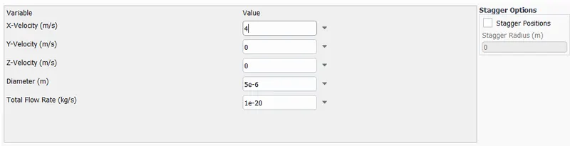
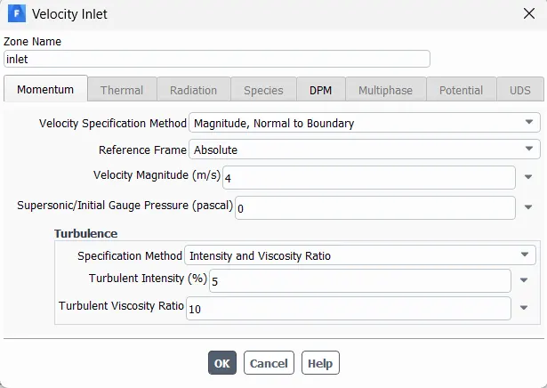
- We will run the calculation for 300 iterations.

Seperation efficiency: 94/124 = 75.80%
RESULTS:
- Anthracite particle time:
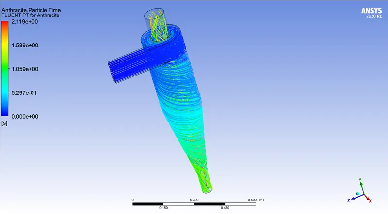
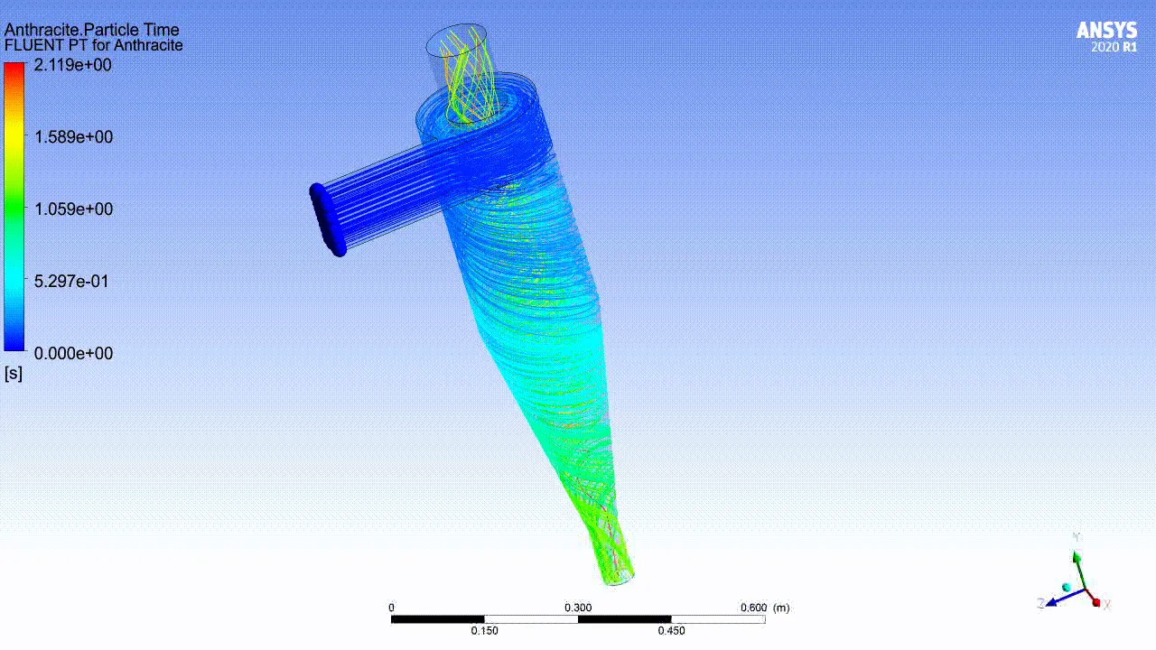
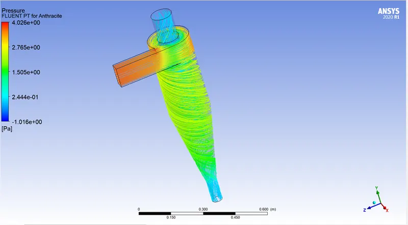
- Pressure:
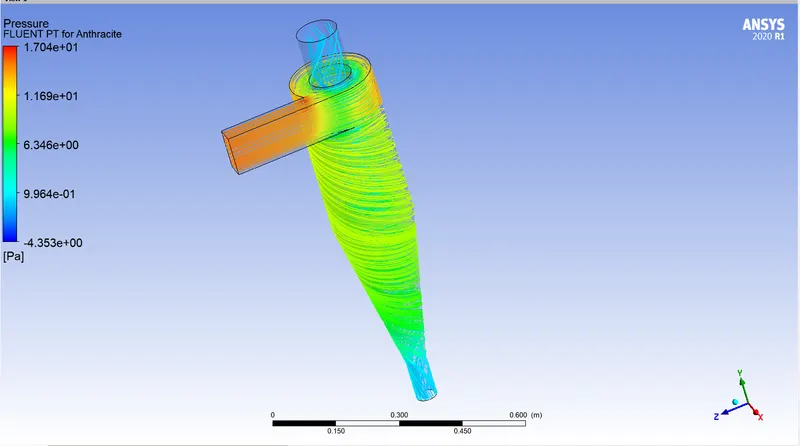
4. Particle velocity = 5m/s
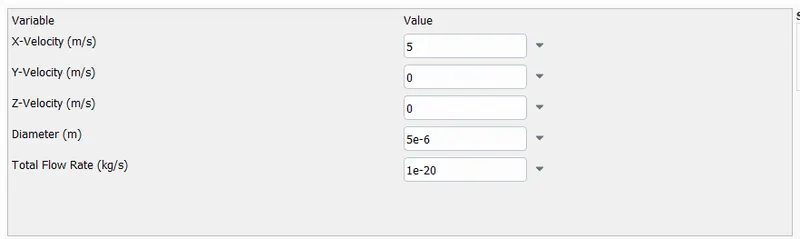
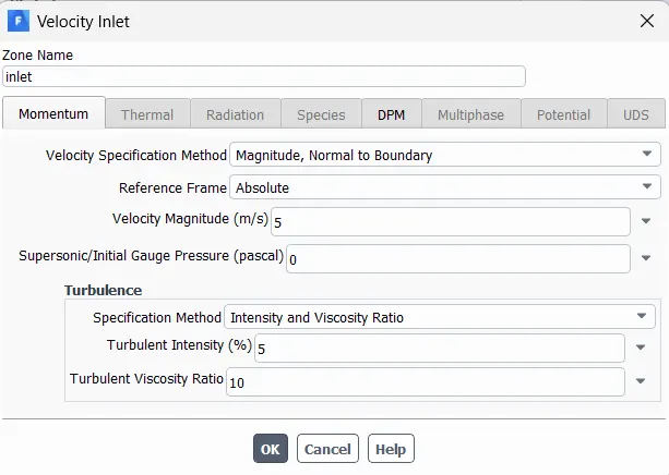
- We will run the calculations for 300 iterations.

Seperation efficiency: 102/124 = 82.25 %
RESULTS:
- Anthracite particle time:
- Pressure:
RESULTS (CASE - 3):
| Sr No | Particle velocity | Seperation efficiency | Escaped particles |
| 1 | 1 m/s | 45.96 % | 52 |
| 2 | 2 m/s | 61.29 % | 44 |
| 3 | 3 m/s | 63.70 % | 45 |
| 4 | 4 m/s | 75.80 % | 30 |
| 5 | 5 m/s | 82.25 % | 22 |
- With increase in particle velocity, number of trapped particles increases which increase the seperation efficiency.
- Particle with low velocity might not have enough momentum to reach till the bottom of the cyclone seperator. Hence, they stop eventually and are carried to the outlet at the top along with the vortex present at the center of the cyclone seperator.
CONCULSION (Final):
- Performed analysis on a cyclone seperator on different cases
- CASE 1: Increasing particle diameter
- CASE 2: Increasing particle velocity.
- With in increase in particle size, the weight of the particle increase causing less number of particles to escape from top outlet and more to get trapped in the bottom outlet.
- With particle velocity, particles with a lower velocity are easily carried to the top outlet as they lose their momentum to reach the bottom outlet and get trapped.