Week 8 - Simulating Cyclone separator with Discrete Phase Modelling
Aim: To perform analysis on the cyclone separator and calculate the separation efficiency and pressure drop.
Objective:
- To develop an understanding of how discrete phase modelling works and implement the same for the given problem.
- To set up the domain and the solver for a cyclone separator and to evaluate the separating efficiency.
- Evaluate the performance based on the changes in particle size (1μm - 5μm; keeping velocity as 3m/s) and inlet velocity (1m/s - 5m/s; keeping particle size as 5μm).
Introduction:
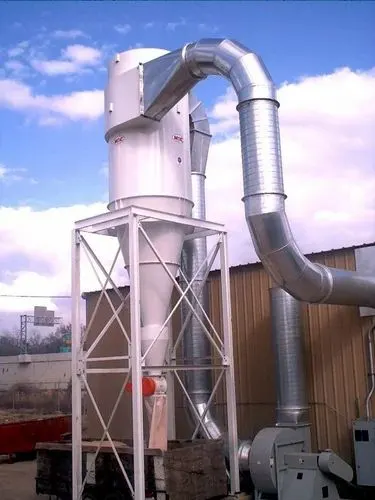
A cyclone separator is a mechanical device that uses centrifugal force to separate particulate matter from a fluid mixture. It typically consists of a cylindrical chamber with a conical outlet and an inlet pipe that introduces the fluid mixture into the chamber. As the fluid enters the chamber, it is spun rapidly, causing the heavier particulate matter to be thrown to the outer wall of the chamber and fall to the bottom, where it is collected. The cleaner fluid exits the chamber through the conical outlet. Cyclone separators are commonly used in industrial settings to remove dust and other particulate matter from air or gas streams.
 |
Discrete Phase Modeling (DPM) is a computational fluid dynamics (CFD) technique used to simulate the motion and behaviour of discrete particles or droplets within a fluid flow. The particles or droplets are treated as individual entities, and their motion is tracked and simulated using equations of motion. DPM is commonly used to model systems such as spray combustion, particle-laden flows, and granular flows.
DPM methods can be divided into two main categories: Eulerian and Lagrangian. Eulerian methods treat the fluid as a fixed grid and track the particles as they move through the grid. Lagrangian methods, on the other hand, track the particles as they move through the fluid and do not use a fixed grid.
DPM simulations can be computationally intensive, and the accuracy of the results depends on the size and shape of the particles, the number of particles simulated, and the accuracy of the mathematical models used to describe the particle motion and interactions. DPM can be used in various fields including, but not limited to: spray combustion, particle-laden flows, granular flows, and multiphase flows. It is widely used to simulate sprays in internal combustion engines, spray drying, spray coating, and many other applications.
Here, by means of DPM, the injected anthracite particles are tracked and a study on the separating efficiency of the clone separator is carried out.
Some empirical relations to evaluate cyclone separator efficiency:
-
Stairmand's equation is an empirical model that relates the efficiency of a cyclone separator to the inlet velocity, the particle size and the cut diameter. The equation is given as:
`eta = (C_1 / sqrt(D_p))*(V_1 / V_2)^4`
Where:
`eta` = Efficiency of the cyclone separator
`C_1` = A constant that depends on the dimensions of the cyclone separator
`D_p` = Particle size (in microns)
`V_1` = Inlet velocity (in m/s)
`V_2` = Outlet velocity (in m/s)
This equation is based on experimental data and is valid for certain ranges of operating conditions. It is generally used to evaluate the efficiency of a cyclone separator for a single particle size and is not suitable for multi-modal particle size distributions.
Note that the constant C1 is a function of the cyclone geometry, and it is obtained by experiments. -
Wen and Yu's equation is an empirical model that relates the efficiency of a cyclone separator to the inlet velocity, the particle size, and the cone angle of the cyclone. The equation is given as:
`eta = (C_2 / sqrt(D_p))*((V_1 / V_2)^4)*(1 - cos(theta))^2`
Where:
`eta` = Efficiency of the cyclone separator
`C_2` = A constant that depends on the dimensions of the cyclone separator
`D_p` = Particle size (in microns)
`V_1` = Inlet velocity (in m/s)
`V_2` = Outlet velocity (in m/s)
`theta` = Cone angle of the cyclone
This equation is also based on experimental data and is valid for certain ranges of operating conditions. It is generally used to evaluate the efficiency of a cyclone separator for a single particle size and is not suitable for multi-modal particle size distributions.
Note that the constant C2 is a function of the cyclone geometry, and it is obtained by experiments. It is important to note that the cone angle of the cyclone plays a significant role in the efficiency of the separator, and a larger cone angle will result in higher efficiency. -
Ermund's equation is an empirical model that relates the efficiency of a cyclone separator to the inlet velocity, the particle size, and the cyclone length-to-diameter ratio. The equation is given as:
`eta = (C_3/D_p)*V_1*(L/D)^4`
Where:
`eta` = Efficiency of the cyclone separator
`C_3` = A constant that depends on the dimensions of the cyclone separator
`D_p` = Particle size (in microns)
`V_1` = Inlet velocity (in m/s)
`L` = Length of the cyclone
`D` = Diameter of the cyclone
This equation is also based on experimental data and is valid for certain ranges of operating conditions. It is generally used to evaluate the efficiency of a cyclone separator for a single particle size and is not suitable for multi-modal particle size distributions.
Note that the constant C3 is a function of the cyclone geometry, and it is obtained by experiments. It is important to note that the length-to-diameter ratio of the cyclone plays a significant role in the efficiency of the separator, and a higher ratio will result in higher efficiency. -
The Rosin-Rammler equation is an empirical model that describes the particle size distribution of a cyclone separator's output. It is often used to evaluate the efficiency of a cyclone separator by relating the size of the particles that are collected in the output to the size of the particles that are present in the input. The equation is given as:
`F(x) = 1 - exp(- (x/x_0)^n)`
Where:
`F(x)` = Cumulative weight fraction of particles smaller than size `x`
`x` = Particle size (in microns)
`x_0` = Median particle size (in microns)
`n` = Shape parameter
The Rosin-Rammler equation is based on experimental data and is commonly used to describe the size distribution of particles in a cyclone separator's output. It can be used to estimate the efficiency of a cyclone separator by comparing the size distribution of the input particles to the size distribution of the output particles.
It is important to note that this equation describes the particle size distribution rather than the efficiency of the separator directly. It is commonly used to analyze the results of experiments, and it is used in combination with other models such as Stairmand's equation, Wen and Yu's equation, and Ermund's equation to evaluate the efficiency of the cyclone separator.
Workflow:
- Preparing the geometry
- Generate mesh for the geometry
- Setting up the solver
- Setting up the solution monitors
- Post-processing to observe the results
Ansys Fluent:
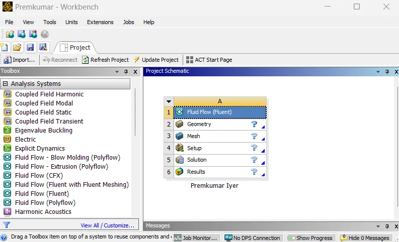 |
In the Ansys workbench project window, Fluid Flow (Fluent) is dropped into the workspace.
Preparing the geometry:
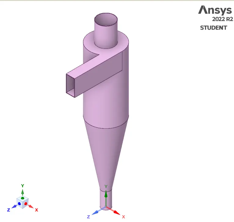
The geometry, as shown (provided as a STEP file) is imported in SpaceClaim. The CAD cleanup work is initiated by finding and eliminating any redundancies. The workbench tab contains tools for this purpose and with the help of these tools, excessive features such as extra lines or surfaces are eliminated. The fluid region is defined by using the volume extract feature available under the prepare tab. The geometry is suppressed for physics and disabled. Only volume extract is kept enabled.
 |
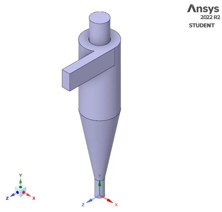 |
| The cyclone separator geometry | Volume Extract |
Generating mesh:
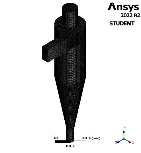
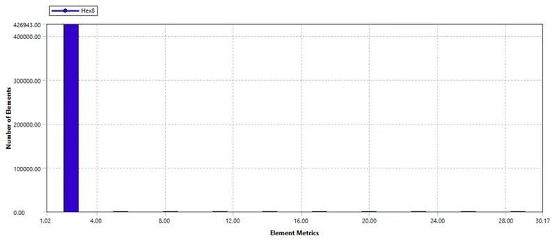
Meshing is the process, wherein the geometry is divided into smaller parts which are known as elements so that the iterative solver can solve the governing equations across the domain. In the meshing utility, a baseline mesh of the default element size is created with capture curvature turned ON. A structural mesh provides better results, hence, method is inserted and body-fitted cartesian mesh is provided. The number of particles tracked in DPM is dependent on the number of cells in the face over which particle injection is provided, thus a further refinement up to 4mm of the element size leads to 427871 number of elements. Thus, we have the following mesh:
 |
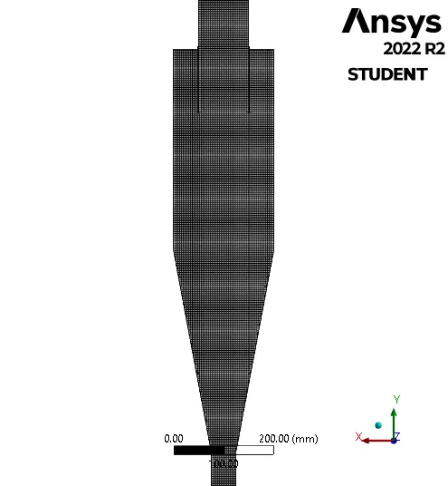 |
| Mesh generated | Sectional View |
 |
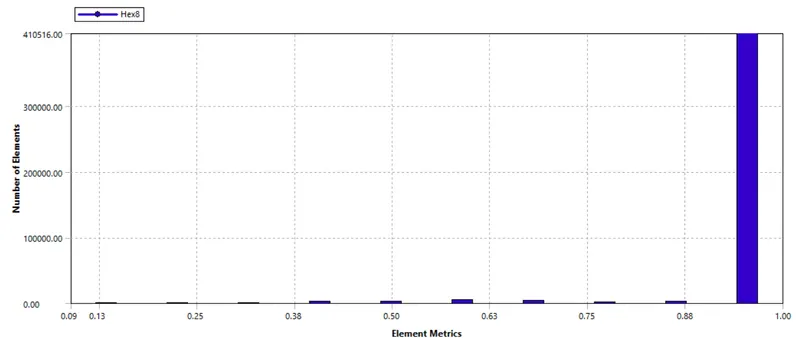 |
| Aspect Ratio | Orthogonal Quality |
For implementing the boundary conditions, the "boundaries" must be clearly defined. To do so, the mesh utility itself has a tool; named selections. By selecting the respective faces and surfaces, the inlet, the particle trap outlet, and the escape outlet were defined.
Setting up the solver:
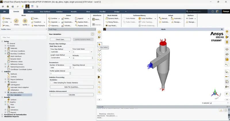 |
An important part of a CFD simulation, the setup for the solver is done to obtain the solution. Firstly, the units of important parameters are set to desired units (preferably SI units). In the general setup, a steady-state pressure-based solver is utilised and gravity is enabled in the y-direction (-9.81`m//s^2)`. In the models tab, in the viscous models, the `k-epsilon` RNG with the swirl-dominated flow and enhanced wall treatment is enabled. In the same tab, the discrete phase option is chosen, with interaction with continuous phase enabled (the fluid and injected particle exchange energy while being in motion). Within this dialogue box, an option for creating injections is present, and by clicking on it particle injection is defined.
The injection type is set to surface and the inlet face is chosen for the same and the particle is injected normal to the face. The particle is of inert type, the material is anthracite and the diameter is uniform. The particle velocity and fluid velocity are kept the same, and an input parameter was created for this. The diameter of the particle is also parameterised and the input for these parameters is provided as per the problem statement.
The fluid zone contains air, and the default properties from the Fluent database are utilised. The boundary condition provided is as follows:
1. Inlet `->` velocity (as input parameter) and DPM is reflect
2. Outlet-trap `->` pressure outlet and DPM is trap
3. Outlet-escape `->` pressure outlet and DPM is escape
The pressure-velocity coupling is set to coupled and the gradient is least squares cell-based, the momentum and pressure are set to second-order discretisation, and the `k` and `epsilon` is set to first-order discretisation. Hybrid initialization is used to initiate the problem, thereafter, 1000 iterations are provided for the solver.
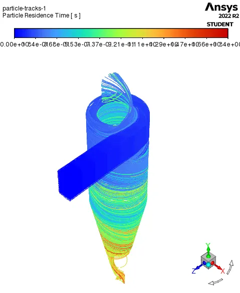
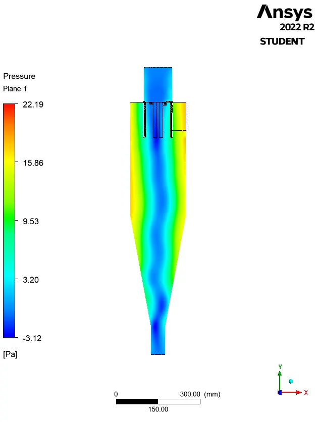
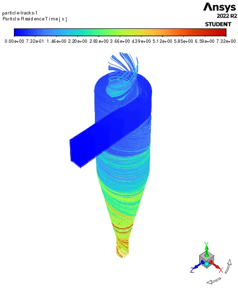
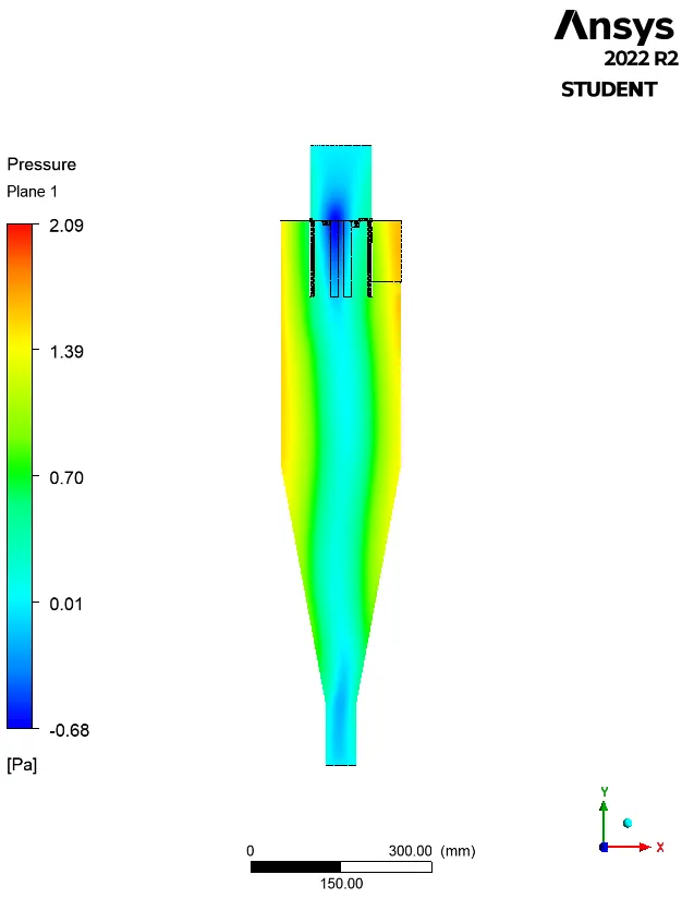
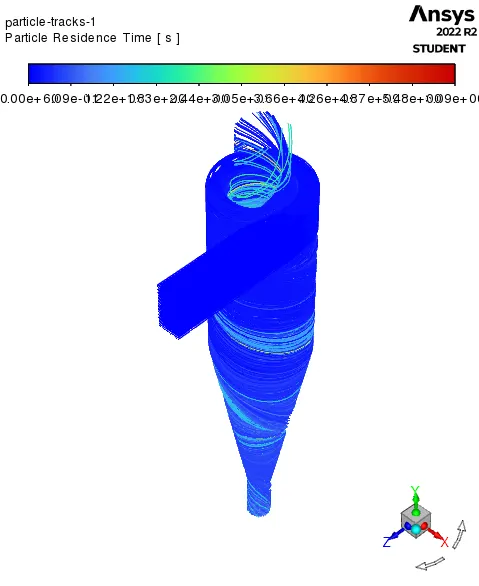
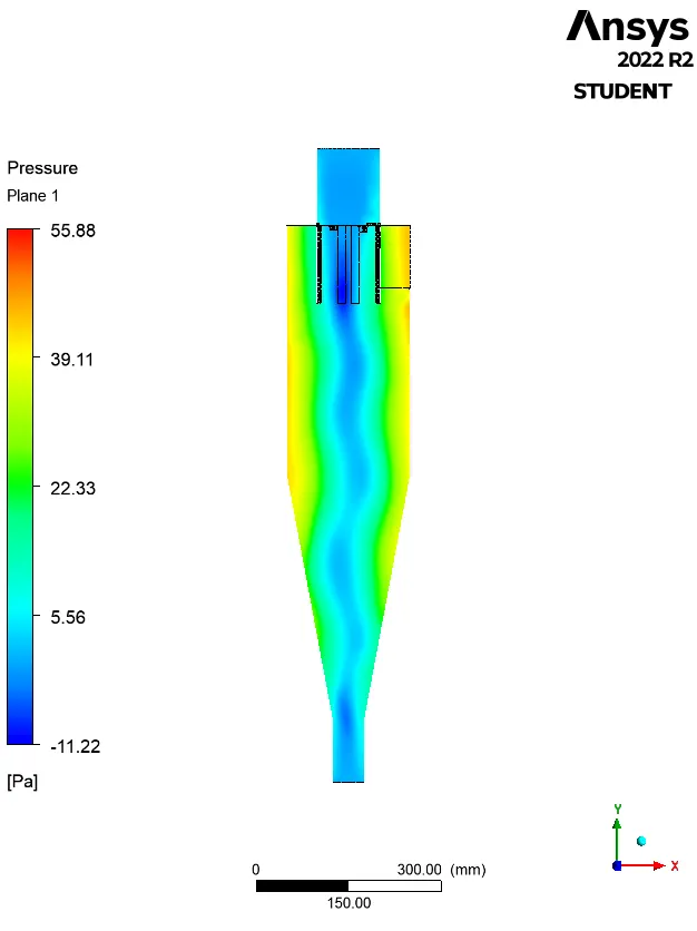
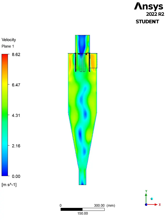
Post-processing (Results):
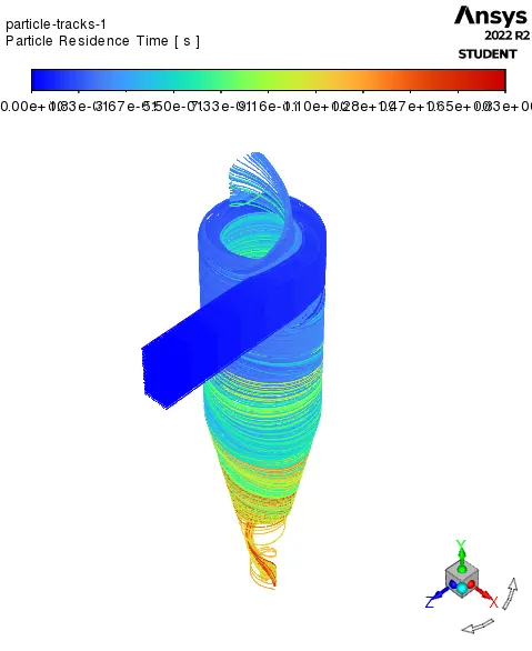
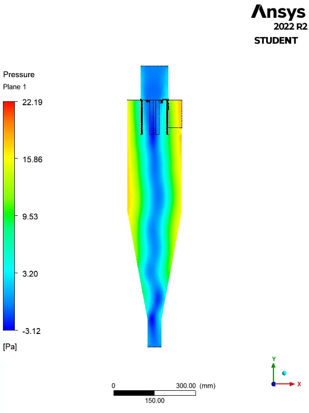
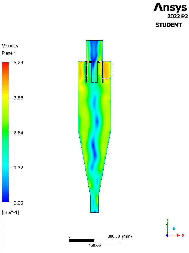
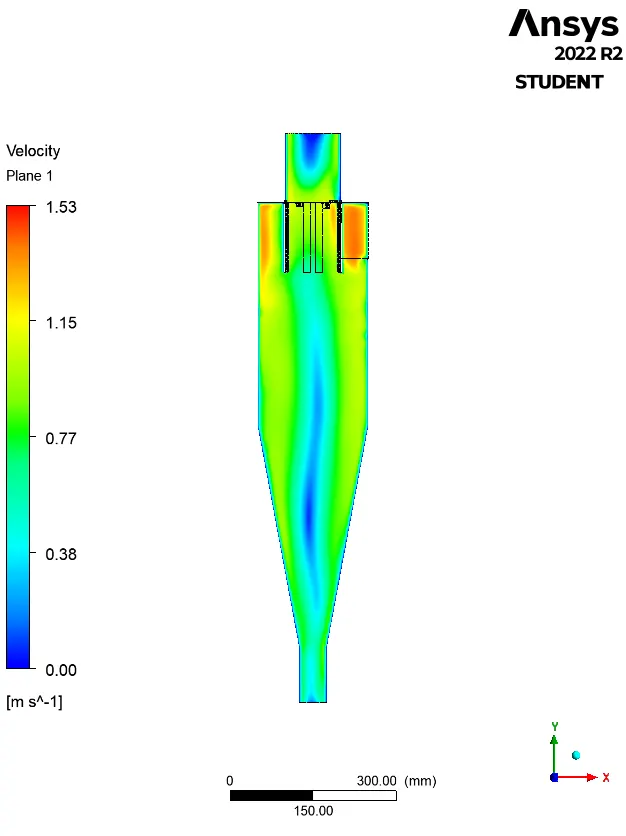
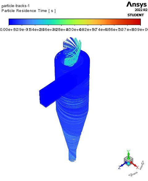
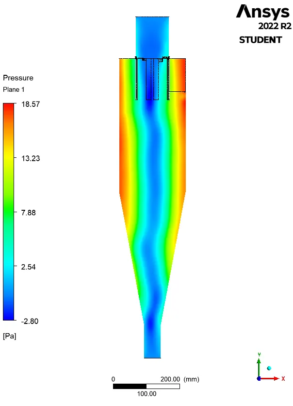
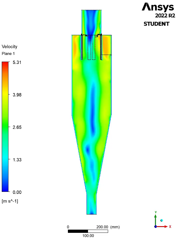
| Particle Size, Particle Velocity |
Particle Residence Time | Pressure Contour | Velocity Contour |
| 1 μm 3 m/s |
 |
 |
 |
| 3 μm 3 m/s |
 |
 |
|
| 5 μm 1 m/s |
 |
 |
 |
| 5 μm 3 m/s |
 |
 |
 |
| 5 μm 5 m/s |
 |
 |
 |
| Particle | |||||
| Size (μm) | Velocity (m/s) | Tracked | Escaped | Trapped | Efficiency |
| 1 | 3 | 378 | 60 | 318 | 84.1270 |
| 3 | 3 | 378 | 59 | 319 | 84.3915 |
| 5 | 1 | 378 | 71 | 307 | 81.2169 |
| 5 | 3 | 378 | 104 | 267 | 70.6349 |
| 5 | 5 | 378 | 66 | 310 | 82.0106 |
| Size (μm) | Velocity (m/s) | Inlet Pressure | Outlet (Escape) Pressure | Outlet (Trap) Pressure | Pressure Drop |
| 1 | 3 | 30.456 | 4.468 | 2.321 | 25.9880 |
| 3 | 3 | 30.541 | 3.845 | 2.332 | 26.6960 |
| 5 | 1 | 2.781 | 0.364 | 0.238 | 2.4170 |
| 5 | 3 | 31.459 | 4.564 | 0.262 | 26.8950 |
| 5 | 5 | 91.159 | 13.516 | 6.564 | 77.6430 |
It is to be noted that the fluid velocity (i.e. velocity of air) at the inlet and the particle velocity is kept same in this simulation.
Conclusion(s):
- The efficiency of a cyclone separator is affected by the size and velocity of the particles it is designed to separate. When the particle size is small, the number of particles trapped is greater, leading to higher efficiency. However, when the particle size is large, the efficiency decreases.
- Additionally, increasing the velocity of the particles results in fewer particles being trapped and more escaping through the outlet, making velocity optimization important.
- It can be concluded that the efficiency of a cyclone separator increases with an increase in particle size and density, as well as the inlet duct velocity, cyclone body length, number of gas revolutions in the cyclone, and the ratio of cyclone body diameter to gas exit diameter.
- However, the efficiency decreases with an increase in gas viscosity, cyclone body diameter, gas exit diameter, and leakage of air into the dust outlet.
- Pressure drop in a cyclone separator is caused by the expansion of gas in the cyclone chamber, rotational kinetic energy, and wall frictional forces.
References:
- Introduction to GUI based CFD using Ansys Fluent - Course provided by Skill-Lync
- Ansys Inc.
- Supporting Material: Energy Education - Cyclone Separator
- Supporting Material: Design of Cyclone Separator Critical Diameter Model Based on Machine Learning and CFD
- Supporting Material: A-TO-Z GUIDE TO THERMODYNAMICS, HEAT & MASS TRANSFER, AND FLUIDS ENGINEERING
- Supporting Material: Fluid Mechanics - Frank M White
- Supporting Material: Fluid Mechanics: Fundamentals and Applications - Y Cengel and J Cimbala