Week 8 - Simulating Cyclone separator with Discrete Phase Modelling
Aim:- To perform analysis on cyclone separator and calculate the separation efficiency and pressure drop using Ansys 2020 R1.
Objective:-
- To give an outlook about any four empirical models used to calculate the cyclone separator efficiency.
- To perform an analysis on a given cyclone separator model by varying the particle diameter from 1 μm to 5 μm and calculate the separation efficiency in each case.
- To perform an analysis on a given cyclone separator model by varying the particle velocity from 1 m/sec to 5 m/sec and calculate the separation efficiency and pressure drop in each case. Discuss the results.
Introduction:
Cyclone seperator: Cyclone seperator is a device used to seperate particles of diameter ranging from 2.5 to 10 micro meters.These devices utilize the principles of centrifugal force in seperating particles.Centrifugal force is generated when a high velocity gas stream is passed through the seperator inlet (the cyclone seperator design makes the gas to move in swirling motion)which is then used to separate particles from the gas (carrier gas).They are simple in construction and setup.And there are no moving parts which makes them cheap and low maintenance costs.They can be designed of any size we desire to be build.They can be robust ,sensitive and can be designed to work under adverse conditions and adaptability to a wide range of operating conditions such as seperating particles from hot gases,dirty fluids etc.
Emperical Methods used to calculate cyclone seperator efficiency:
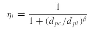

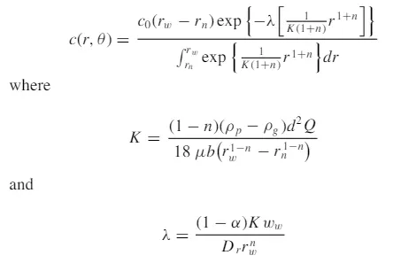
- The radial particle velocity and the radial concentration profile are not constant for uncollected particles within the cyclone.
- Boundary conditions with the consideration of turbulent diffusion coefficient and particle bounce re-entrainment on the cyclone wall are:
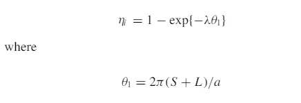
Koch and Licht Mode:
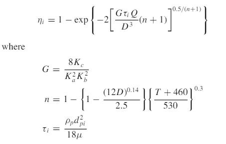
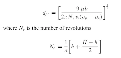
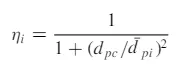
Koch and Licht collection theory recognized turbulent nature of cyclones and the spreading of gas residence periods within the cyclone. Koch and Licht defined particle motion in the entry and collection locations with the below assumptions:
- The tangential velocity of the particle is equal to the tangential velocity of the gas flow, i.e. there is no slip in the tangential direction between gas and the particle.
- The tangential velocity is related to the radius of cyclone by: u R^n= constant.
Problem solving and modelling approach:
Geomenty setup:
The cyclone seperator model is imported to the space claim
Meshing:
Meshing is performed with element size of 10mm
Pre-processing:
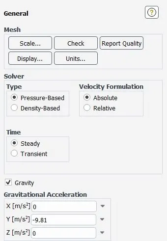
Pressure based solver is used with steady state and a gravity box is checked and given a value of -9.81 in y axis.
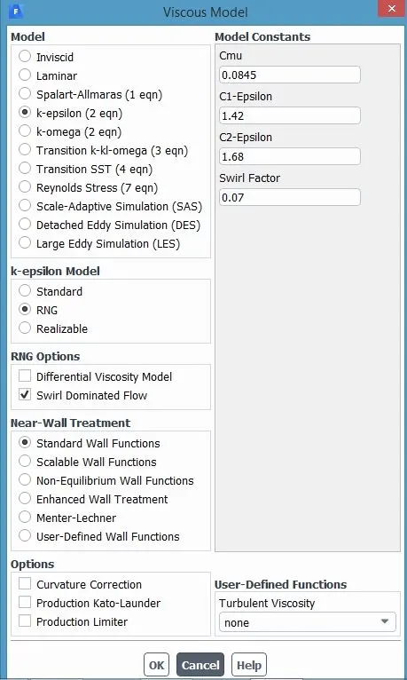
In the viscous model k-epsilon model with RNG and swil dominated option is selected with standard wall function.
Discretisation :
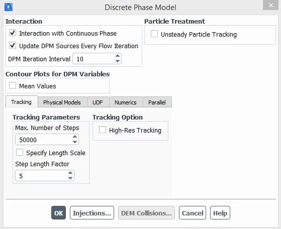
Discretisation phase is switched on because there is a discrete particle flow along with the continous flow.
Interaction with continous flow is checked because there is an combined flow of discrete and continuous flow particles.
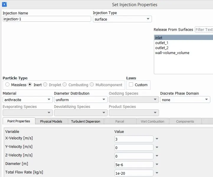
Injection of particles setup is done by defining the particle velocity and size.Material anthracite is selected.
Given Boundary Conditions:-
Inlet and wall:- Reflect
Outlet(Top):- Escape
Outlet(Bottom/dustbin) - Trap
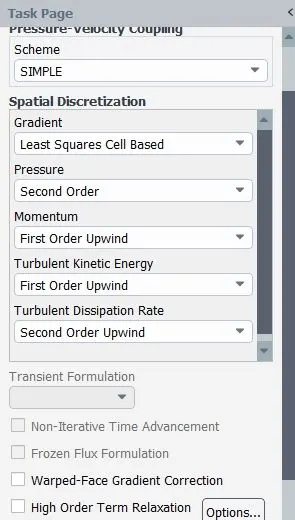
Solution methods are selected
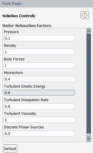
Solution controls:
In case1 velocity is maintained same (3m/s) and particle size is kept varying from 1 to 5 micro meters
| Case1 | velocity (m/sec) | size of particle(μm) |
| 1.a | 3 | 1 |
| 1.b | 3 | 2 |
| 1.c | 3 | 3 |
| 1.d | 3 | 4 |
| 1.e | 3 | 5 |
Case 1.a particle size 1(μm)
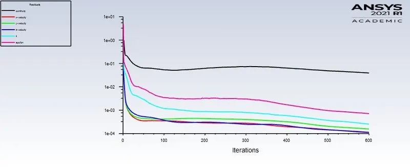
Residuals:
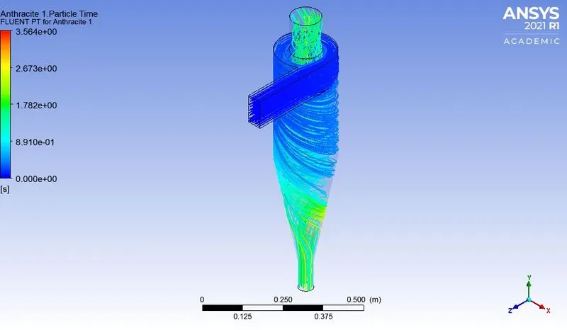
Particle time:
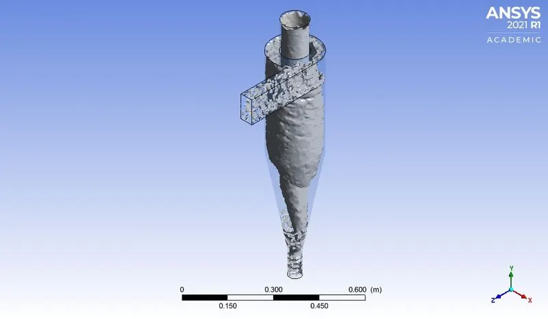
Vortex contour:
Seperation Efficiency:

Seperation efficiency=Number of particles trapped /Total number of particles tracked
=61/120
=50.83%
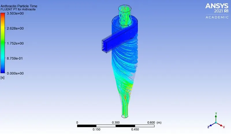
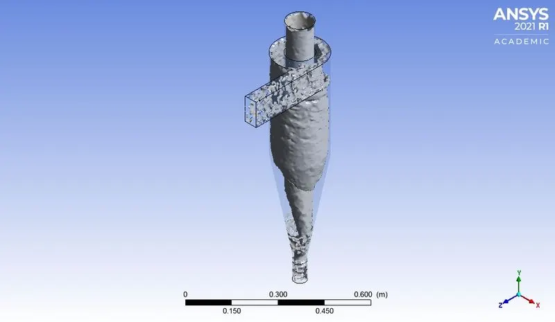
Case 1.b particle size 2 μm
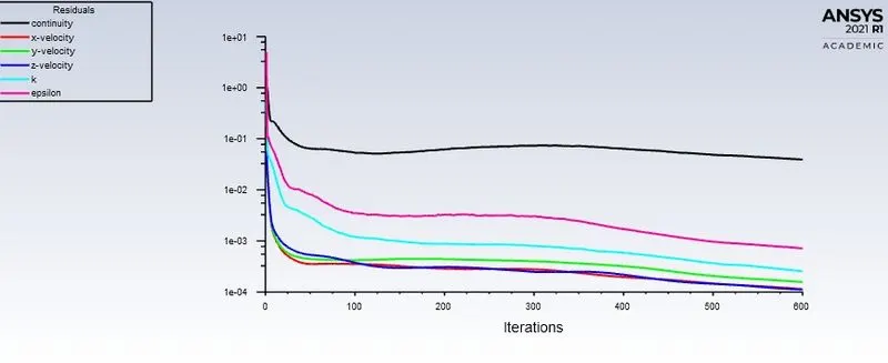
Residuals:
Particle time:
Vortex contour:
Seperation Efficiency:

Seperation efficiency=Number of particles trapped /Total number of particles tracked
=62/120
=51.67%
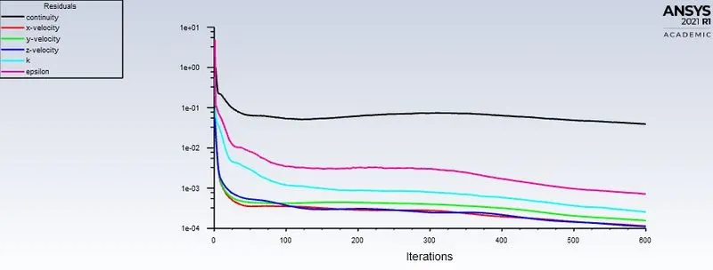
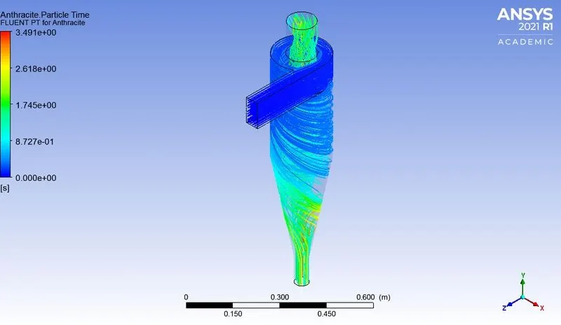
Case 1.c particle size 3 μm
Residuals:
Particle time:
Vortex contour:
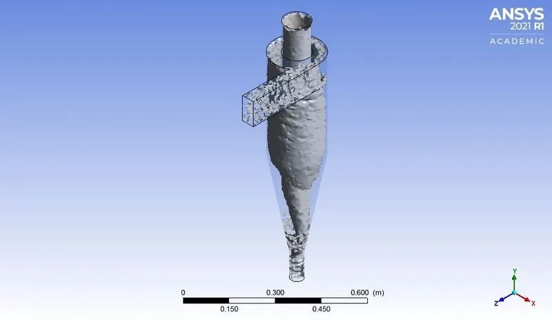
Seperation Efficiency:

Seperation efficiency=Number of particles trapped /Total number of particles tracked
=67/120
=55.8%
Case 1.d particle size 4 μm
Residuals:
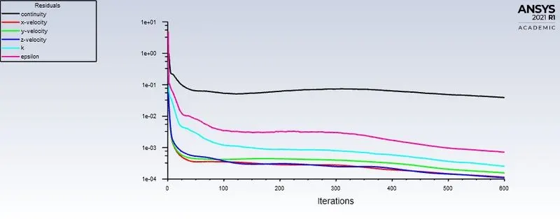
Particle time:
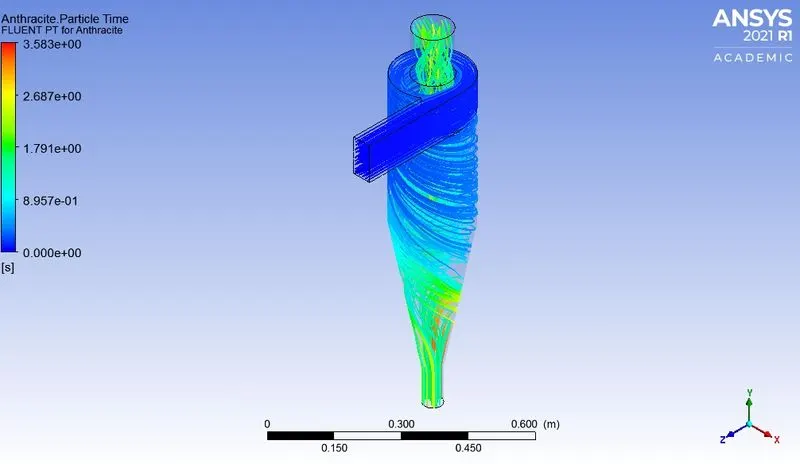
Vortex contour:
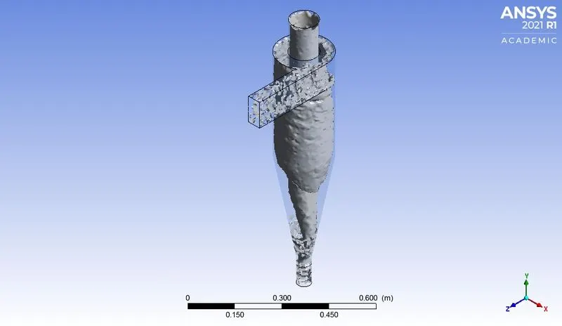
Seperation Efficiency:

Seperation efficiency=Number of particles trapped /Total number of particles tracked
=70/120
=58.3%
Case 1.e particle size 5 μm
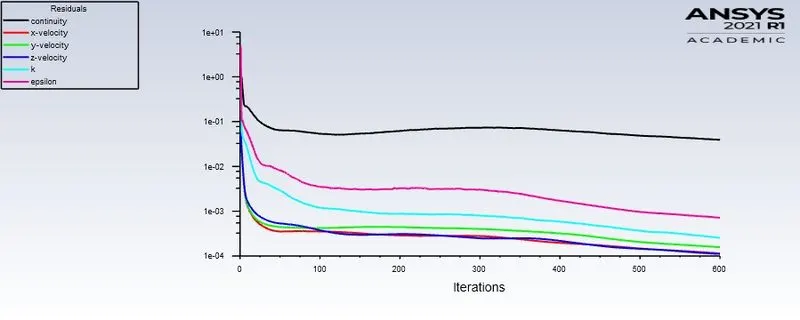
Residuals:
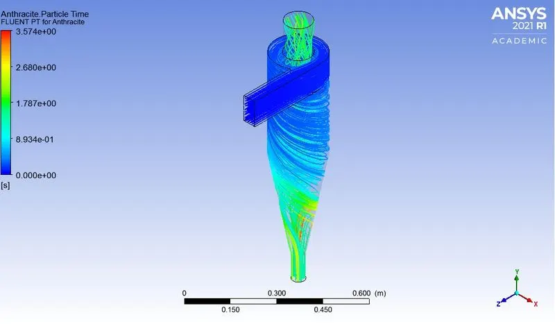
Particle time:
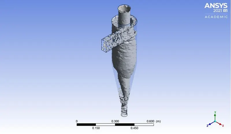
Vortex contour:
Seperation Efficiency:

Seperation efficiency=Number of particles trapped /Total number of particles tracked
=77/120
=64.2%
- with the increasing velocity the seperation efficiency is increasing
In case2 particle dia is maintained same and particle velocity is kept varying from 1 to 5 m/s
| Case2 | velocity (m/sec) | size of particle (μm) |
| 2.a | 1 | 5 |
| 2.b | 2 | 5 |
| 2.c | 3 | 5 |
| 2.d | 4 | 5 |
| 2.e | 5 | 5 |
Case 2.a particle velocity 1m/s
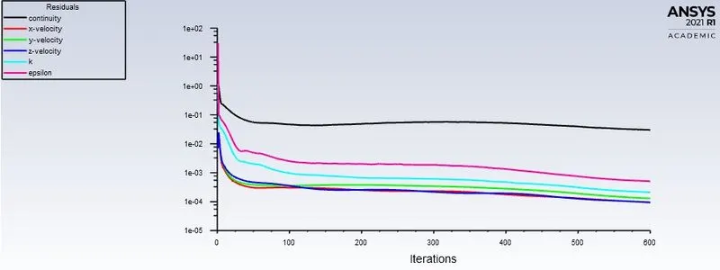
Residuals:
Particle time:
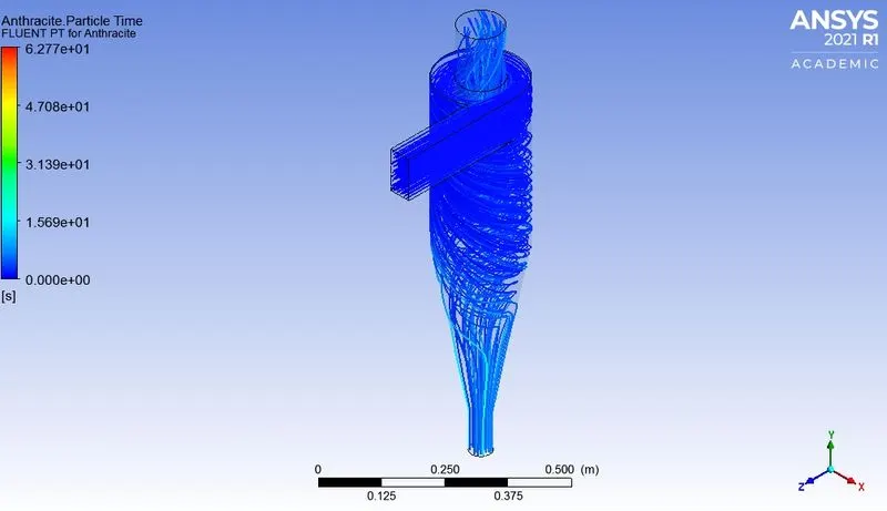
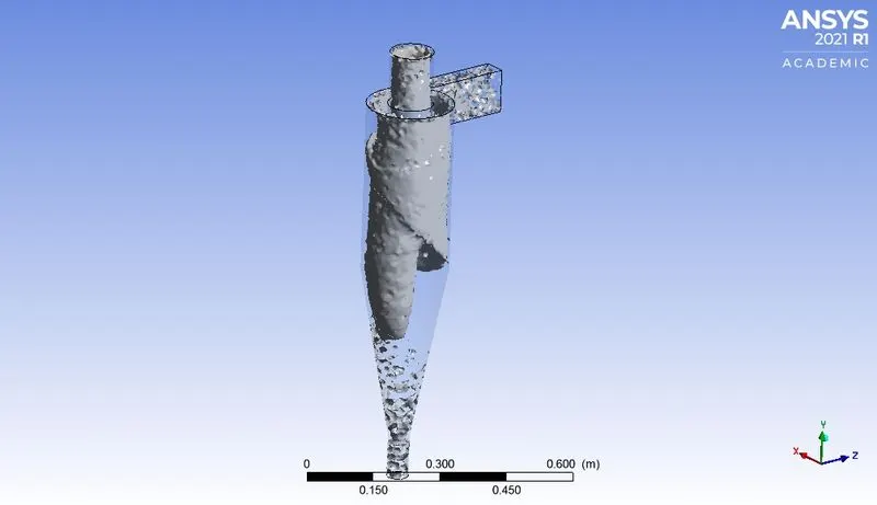
Vortex contour:
Pressure contour:
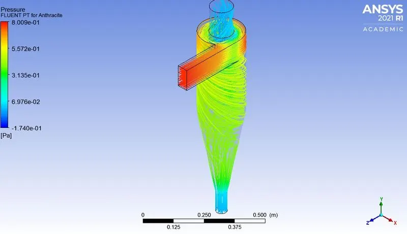
Pressure drop:
Pressure drop is the difference in the total pressure between two points of a fluids.
Seperation Efficiency:

Seperation efficiency=Number of particles trapped /Total number of particles tracked
=48/120
=40%
Case 2.b particle size 2m/s
Residuals:
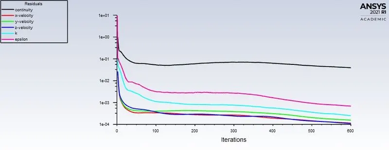
Particle time:
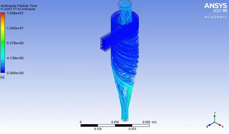
Vortex contour:
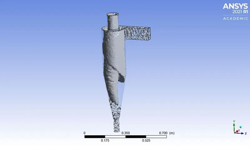
Pressure contour:
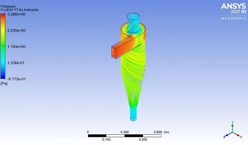
Seperation Efficiency:

Seperation efficiency=Number of particles trapped /Total number of particles tracked
=65/120
=53.3%
Case 2.c particle size 5 μm
Residuals:
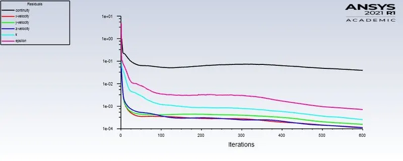
Particle time:
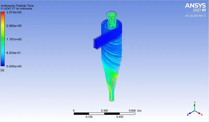
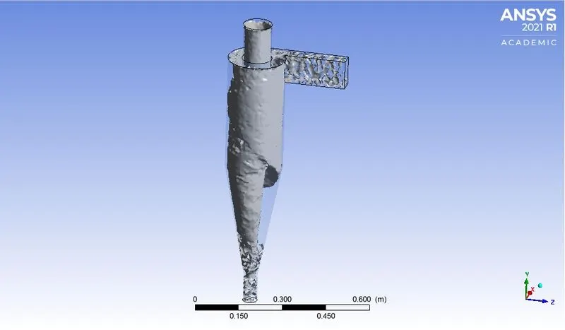
Vortex contour:
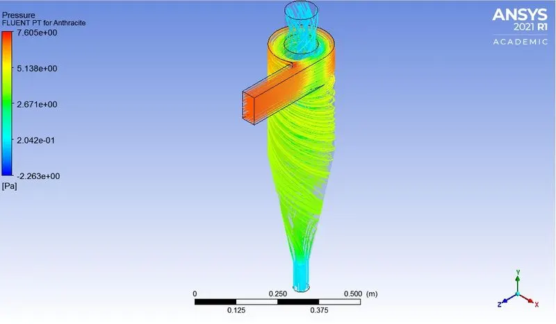
Pressure contour:
Seperation Efficiency:

Seperation efficiency=Number of particles trapped /Total number of particles tracked
=77/120
=64.2%
Case 2.d particle size 5 μm
Residuals:
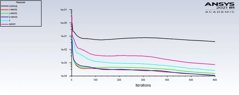
Particle time:
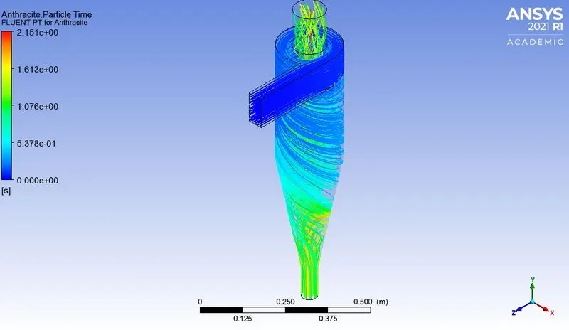
Vortex contour:
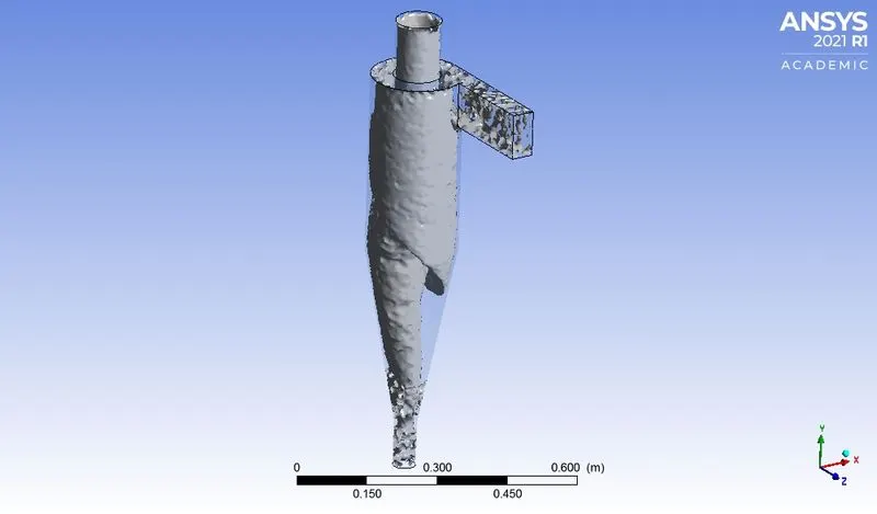
Pressure contour:
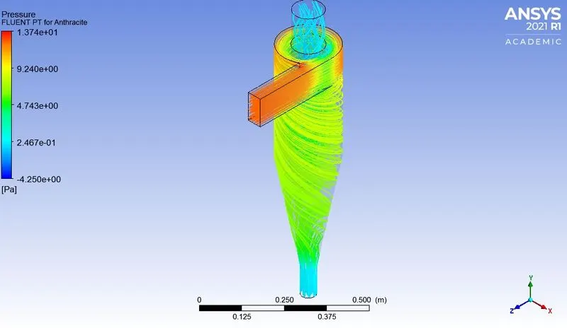
Seperation Efficiency:

Seperation efficiency=Number of particles trapped /Total number of particles tracked
=81/120
=67.5%
Case 2.e particle size 5 μm
Residuals:
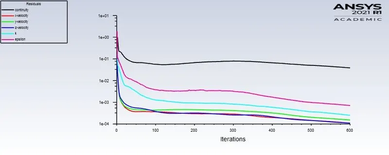
Particle time:
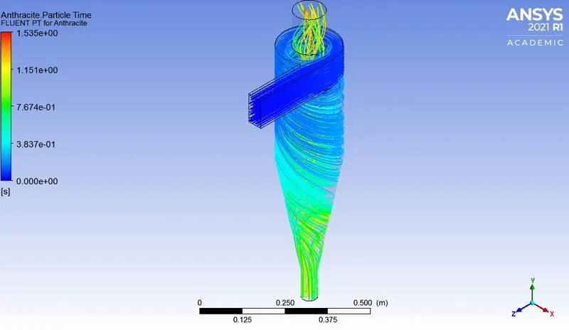
Vortex contour:
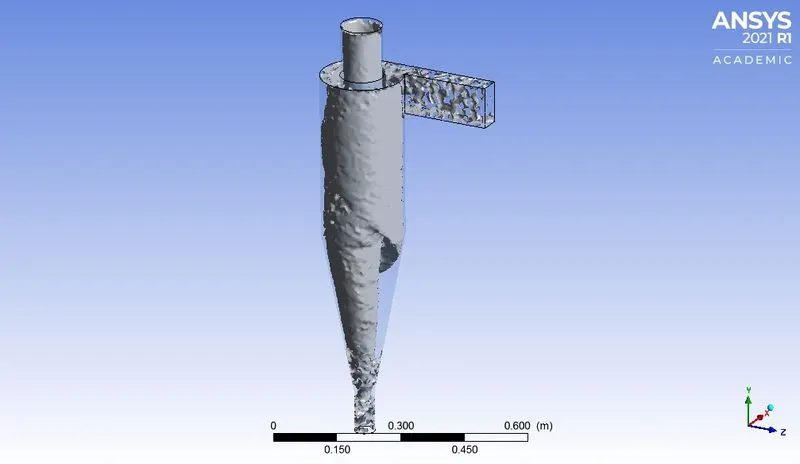
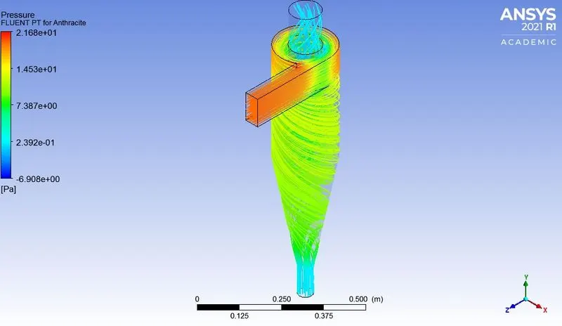
Pressure contour:
Seperation Efficiency:

Seperation efficiency=Number of particles trapped /Total number of particles tracked
=83/120
=70%
In case1 velocity is maintained same and particle size is kept varying from 1 to 5 micro meters
| Case1 | velocity (m/sec) | size of particle(μm) | Efficiency(%) |
| 1.a | 3 | 1 | 50.83 |
| 1.b | 3 | 2 | 51.67 |
| 1.c | 3 | 3 | 55.8 |
| 1.d | 3 | 4 | 58.3 |
| 1.e | 3 | 5 | 64.2 |
In case2 velocity is maintained same and particle size is kept varying from 1to 5 micro meters
| Case2 | velocity (m/sec) | size of particle(μm) | Pressure drop(Pa) | Efficiency(%) |
| 2.a | 1 | 5 | 1.2 | 40 |
| 2.b | 2 | 5 | 3.28 | 53.3 |
| 2.c | 3 | 5 | 7.6 | 64.2 |
| 2.d | 4 | 5 | 13.7 | 67.5 |
| 2.e | 5 | 5 | 29 | 70 |
Conclusion:
- With the increase in the particle size the efficiency is increasing but the change in the efficiency with the partcle size is very gradual.
- It is observed that the efficiency of the cyclone seperator increases with the increase in the particle velocity.With the slight increase in the velocity the efficiency is improved drastically.
- Velocity plays an important role in the seperation efficiency of the cyclone seperator.
- The prossure drop increases with the increase in the flow velocity,with the pressure drop also the efficiency of the seperator is increased.
References: