Week 8 - Simulating Cyclone separator with Discrete Phase Modelling
Aim:- To perform analysis on cyclone separator and calculate the separation efficiency and pressure drop.
Introduction & theory:
- As the cyclone is essentially a two phase particle-fluid system, fluid mechanics and particle transport equations can be used to describe the behaviour of a cyclone. The air in a cyclone is initially introduced tangentially into the cyclone with an inlet velocity (Vin). Assuming that the particle is spherical, a simple analysis to calculate critical separation particle sizes can be established.
- Cyclone separators or simply cyclones are separation device that use the principle of inertia to remove particulate matter from flue gases.
working:
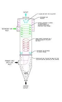
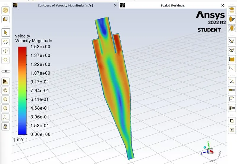
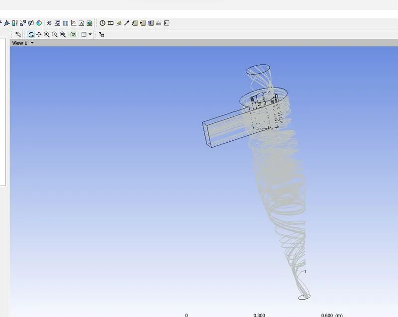
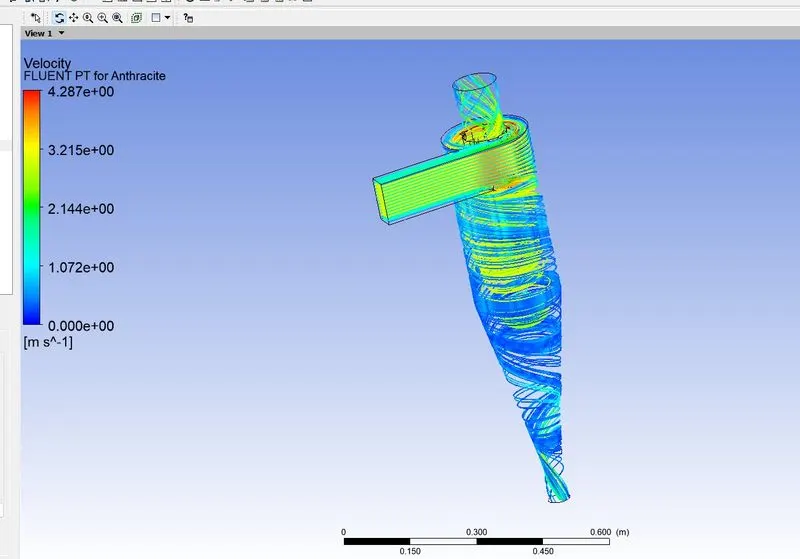
Cyclone separators work much like a centrifuge, but with a continuous feed of dirty air. In a cyclone separator, dirty flue gas is fed into a chamber. The inside of the chamber creates a spiral vortex, similar to a tornado. This spiral formation and the separation . The lighter components of this gas have less inertia, so it is easier for them to be influenced by the vortex and travel up it. Contrarily, larger components of particulate matter have more inertia and are not as easily influenced by the vortex.
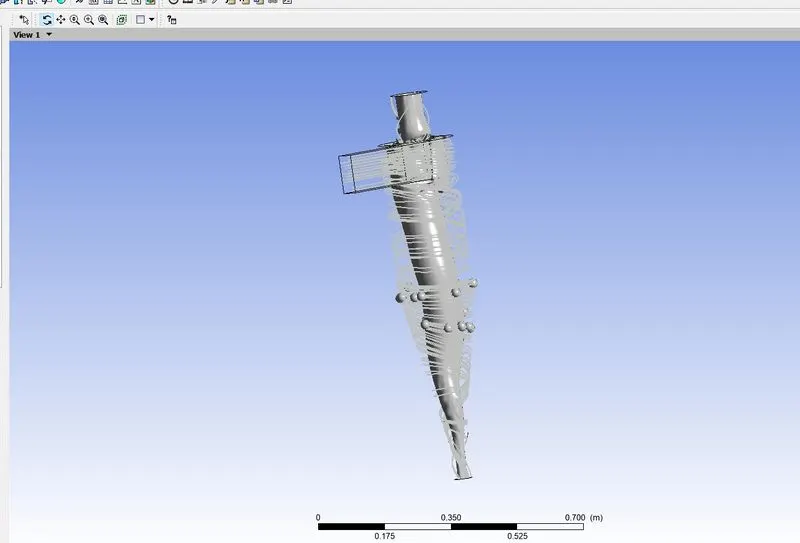
Since these larger particles have difficulty following the high-speed spiral motion of the gas and the vortex, the particles hit the inside walls of the container and drop down into a collection hopper.
Most cyclones are built to control and remove particulate matter that is larger than 10 micrometers in diameter. However, there do exist high efficiency cyclones that are designed to be effective on particles as small as 2.5 micrometers.
Modelling:
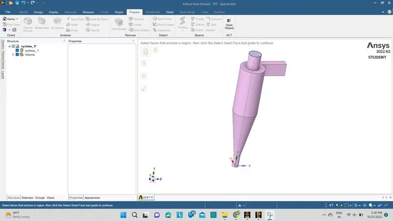
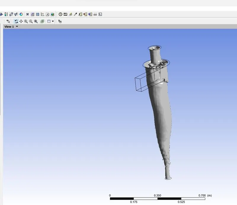
- Rightclick_open space claim_files_open _cyclone_separator
- spaceclaim_prepare_volumeExtract_by selecting each edge.
- spaceclaim_ structure_right click on geometry_supress for physics(solid domain)
Mesh:
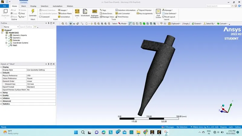
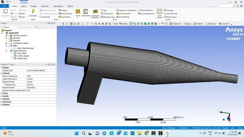
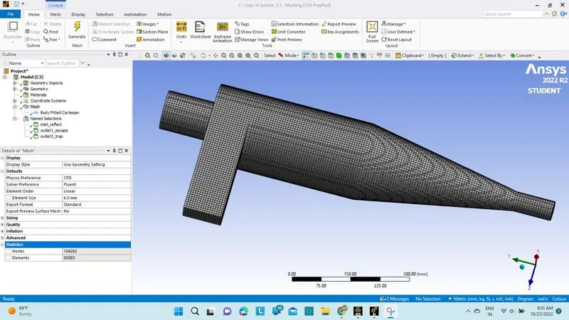
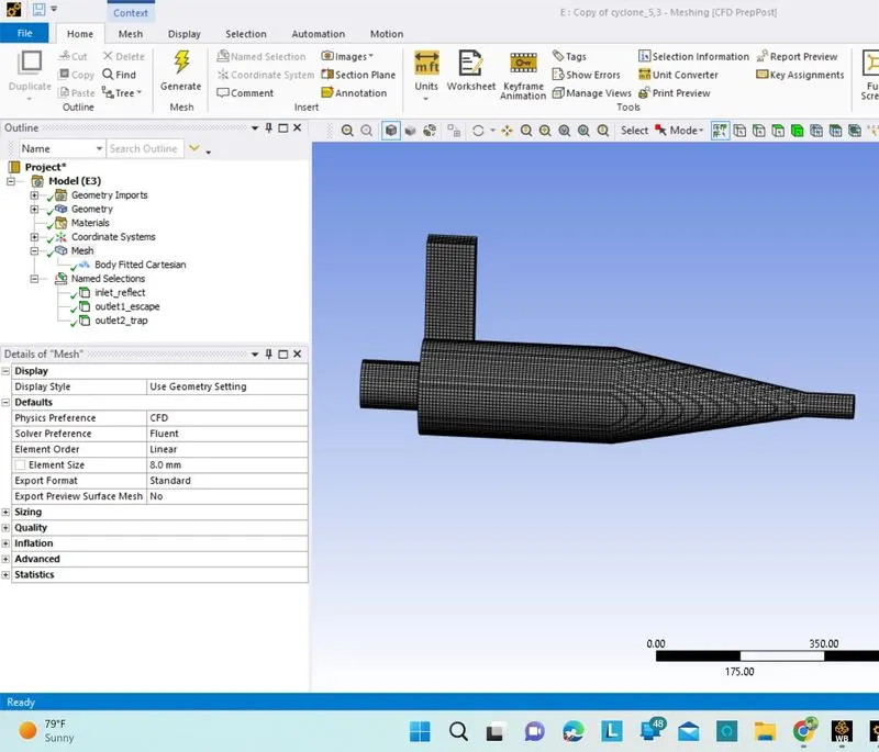
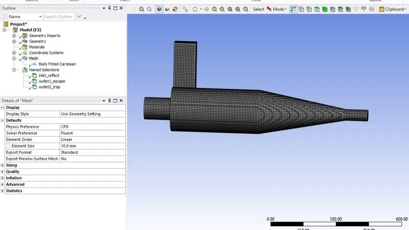
- Open _spaceclaim model to Mesh
- Rightclick_mesh_generate mesh(10mm)
Fluent:
Open_fluent_
Fluent_Enable gravity.
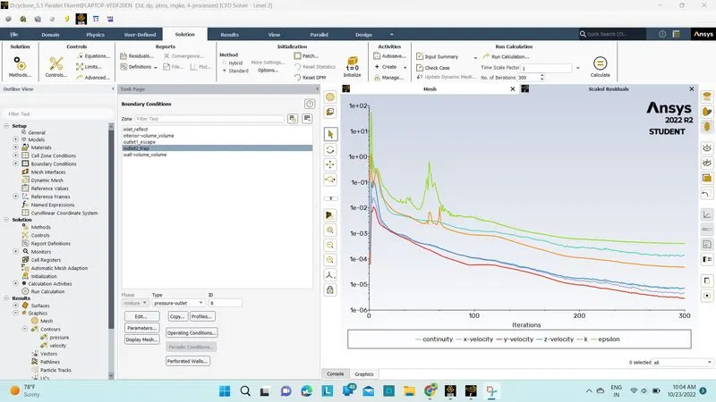
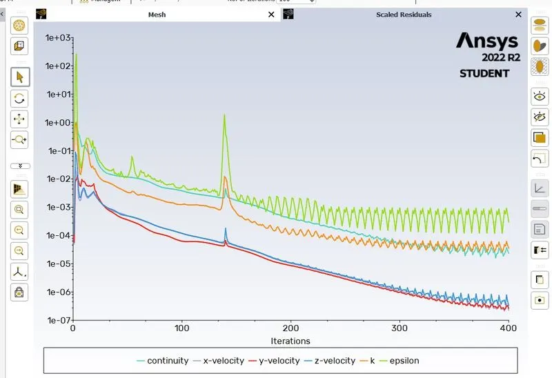
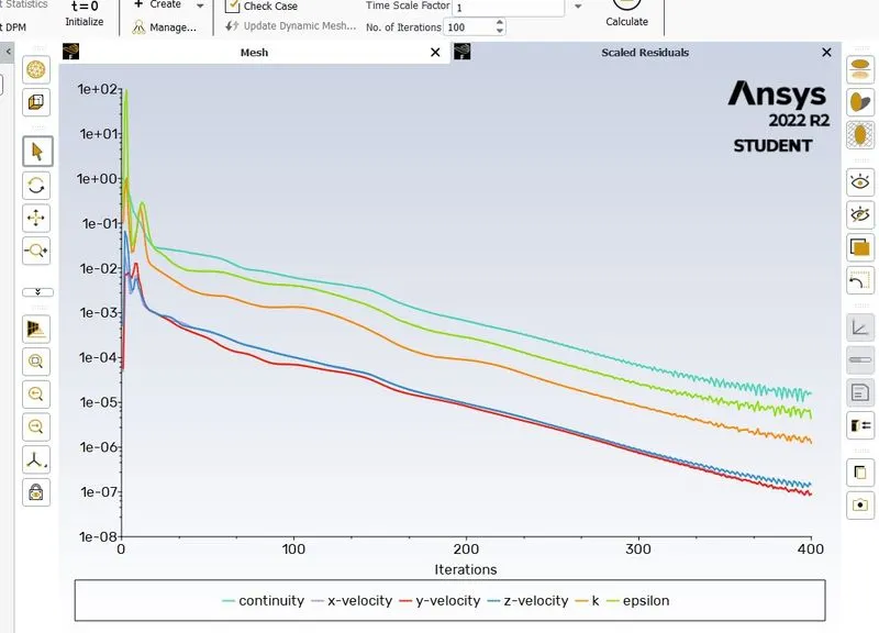
Fluent_Enable steady_state
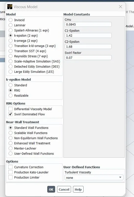
Fluent_physics_viscous_Enable K_episilon
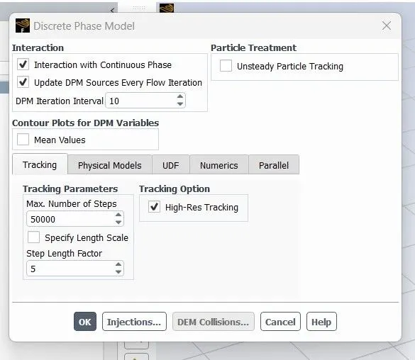
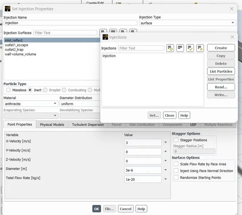
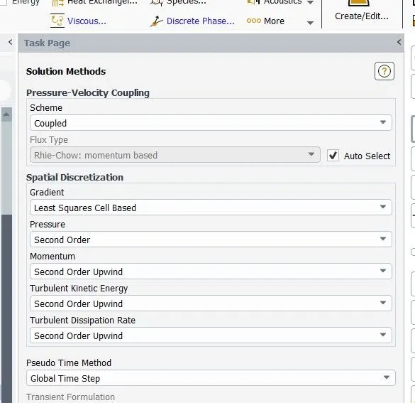
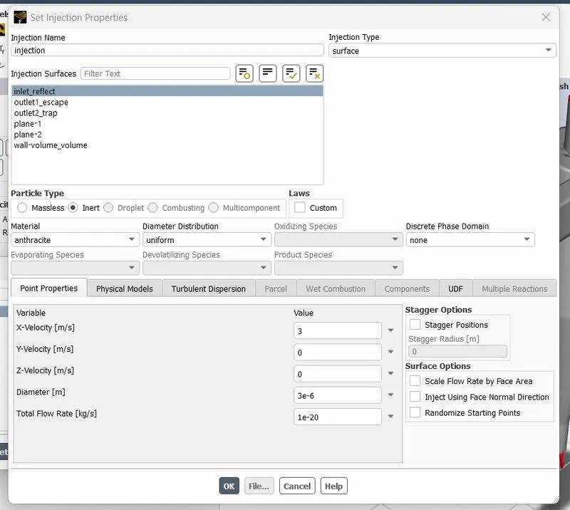
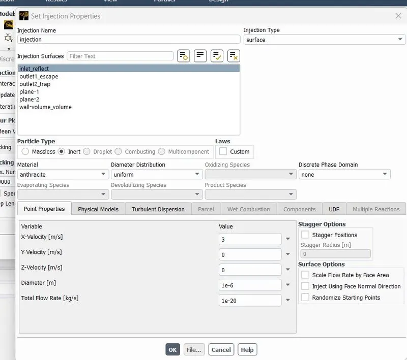
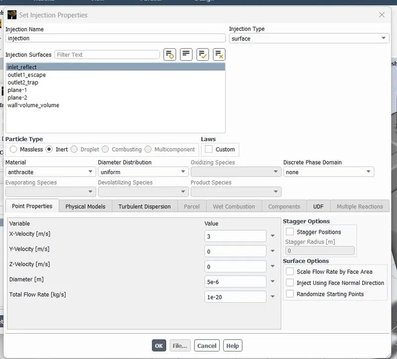
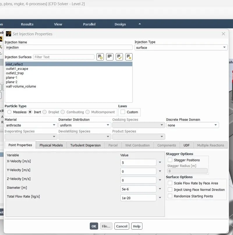
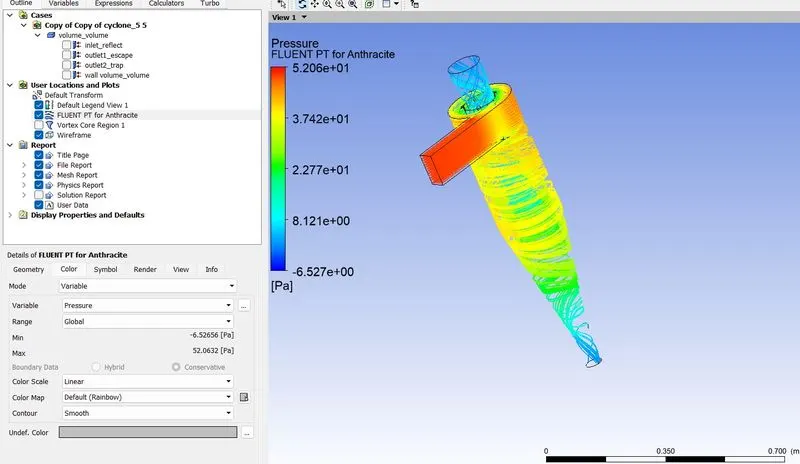
Fluent_physics_Discrete phase & Injection.
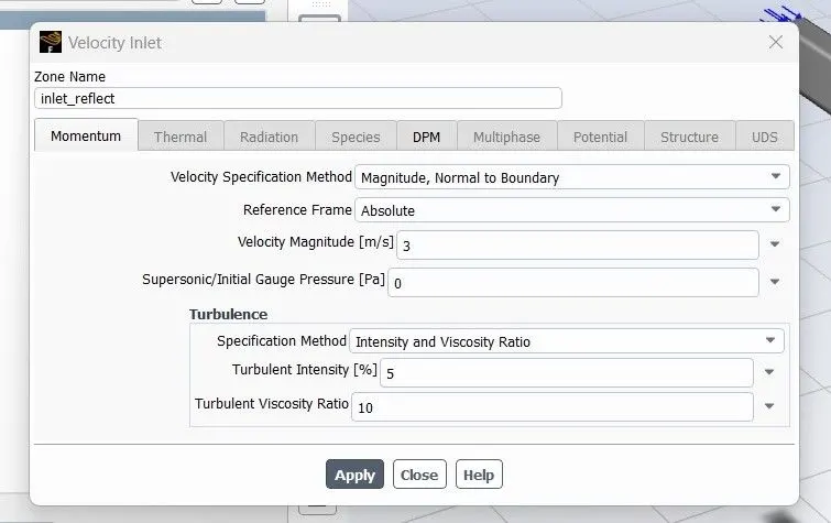
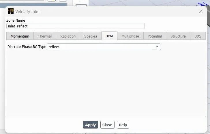
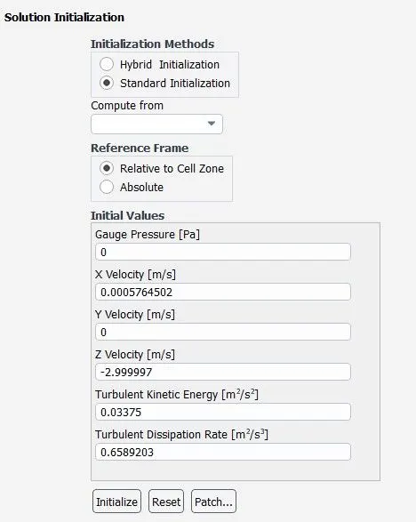
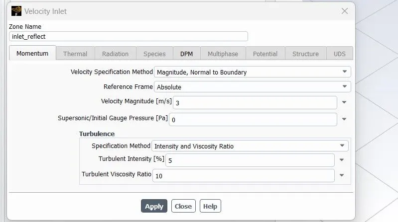
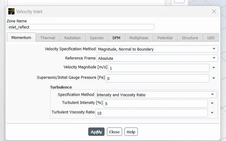
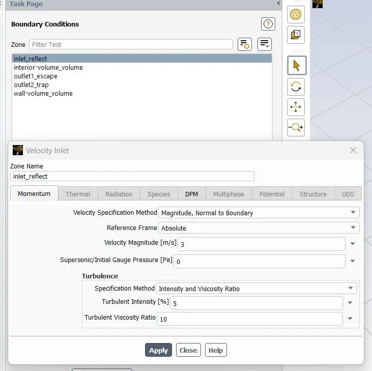
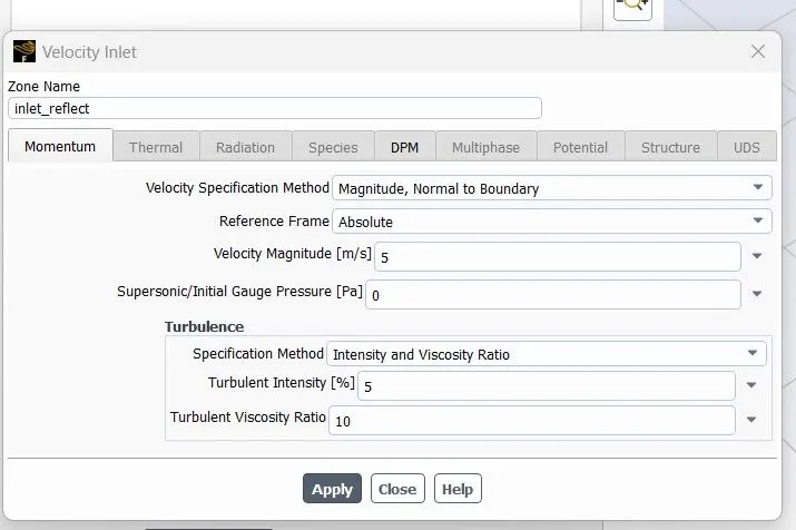
Fluent_Set boundaryconditions.
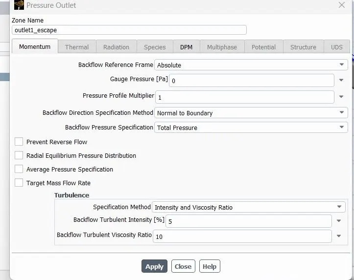
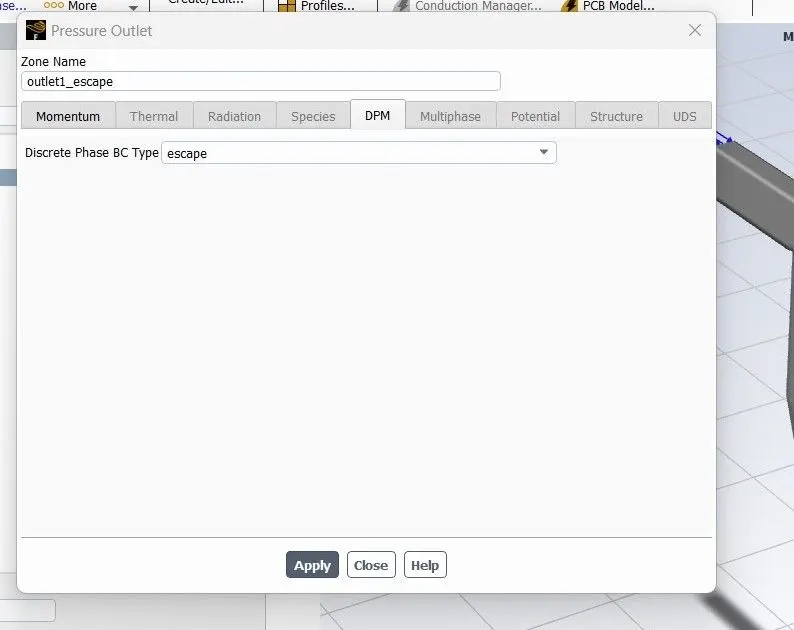
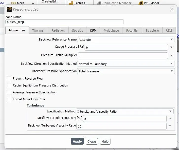
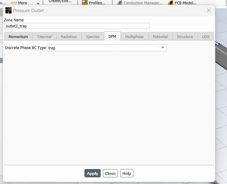
Conditions:
1.
Particle _ diameter(Pd)=[1 3 5]
velocity(Pv)=3m/sec
2.
Particle _Velocity(Pv)=[ 1 3 5]
diameter(Pd)=5
3.
Mesh=[6 8 10]
Case1:
pd=5e-6
pv=3
Mesh=10mm
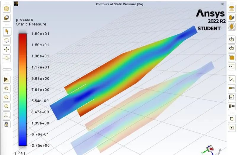
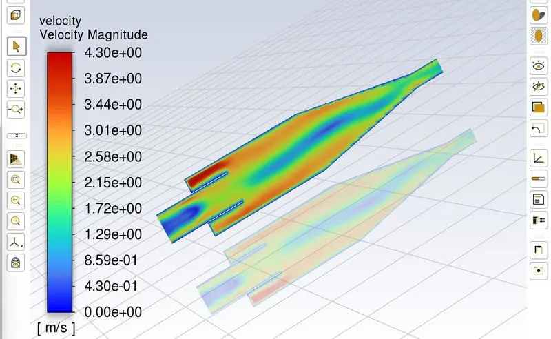
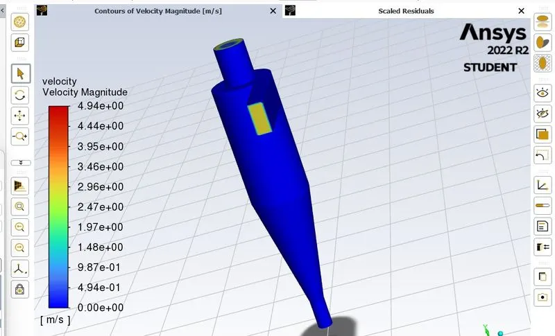
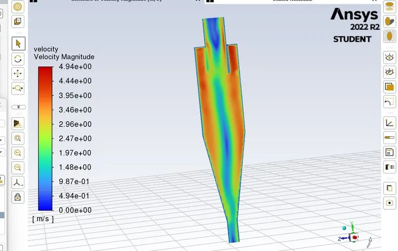
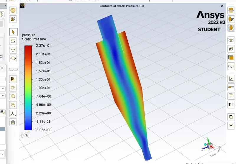
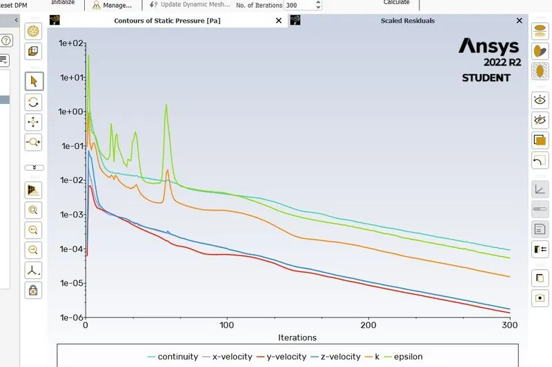
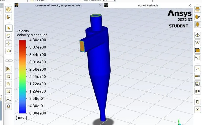
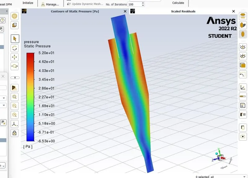
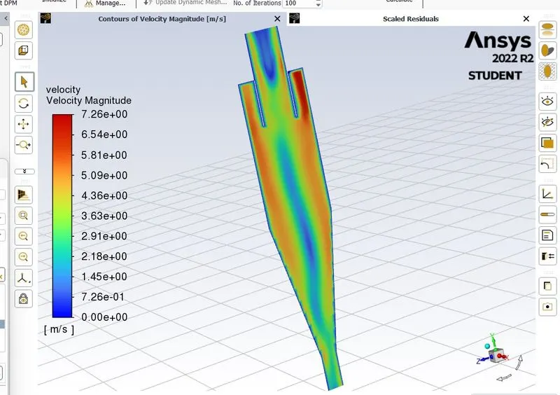
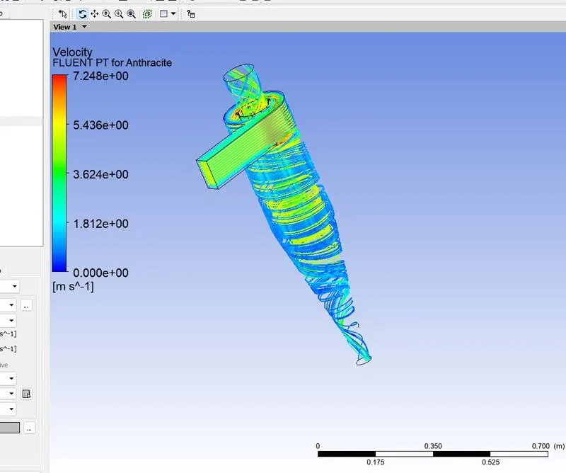
Results1:
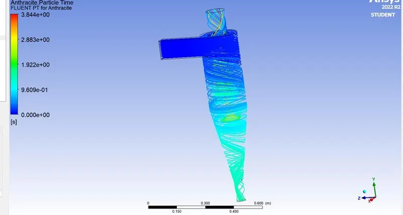
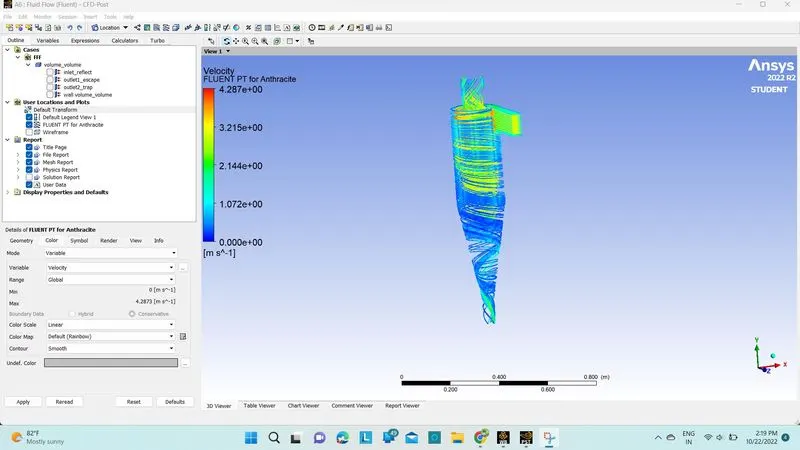
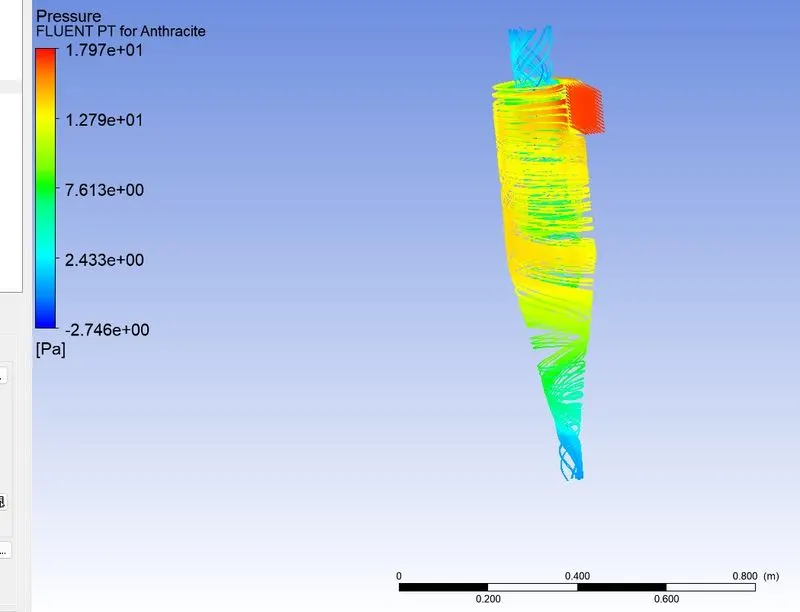
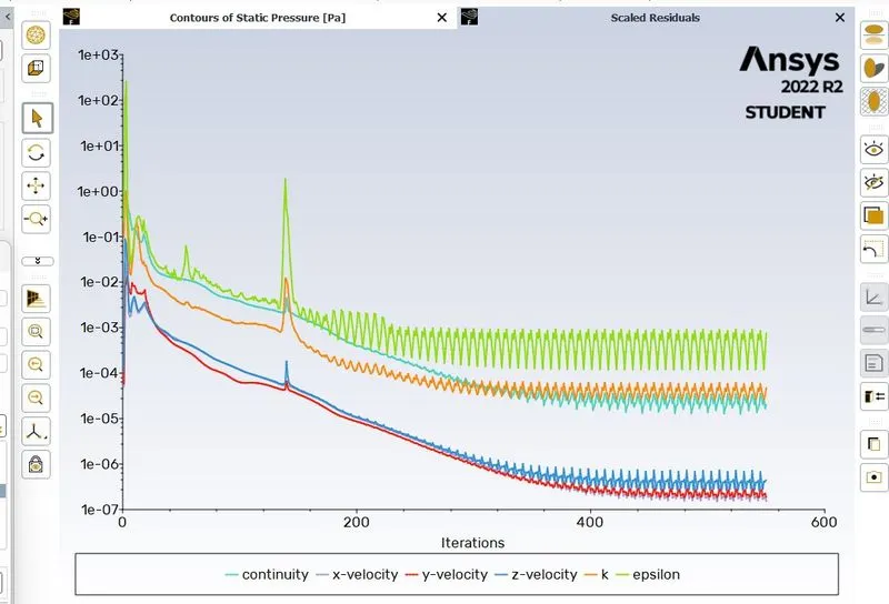
Case2:
pd=3e-6
pv=3
Mesh=8mm
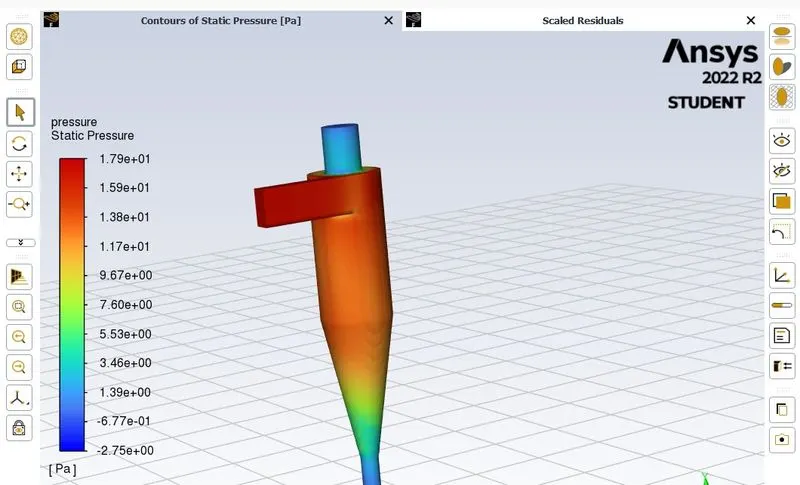
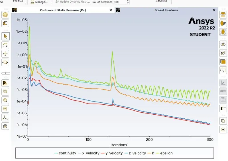
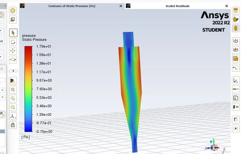
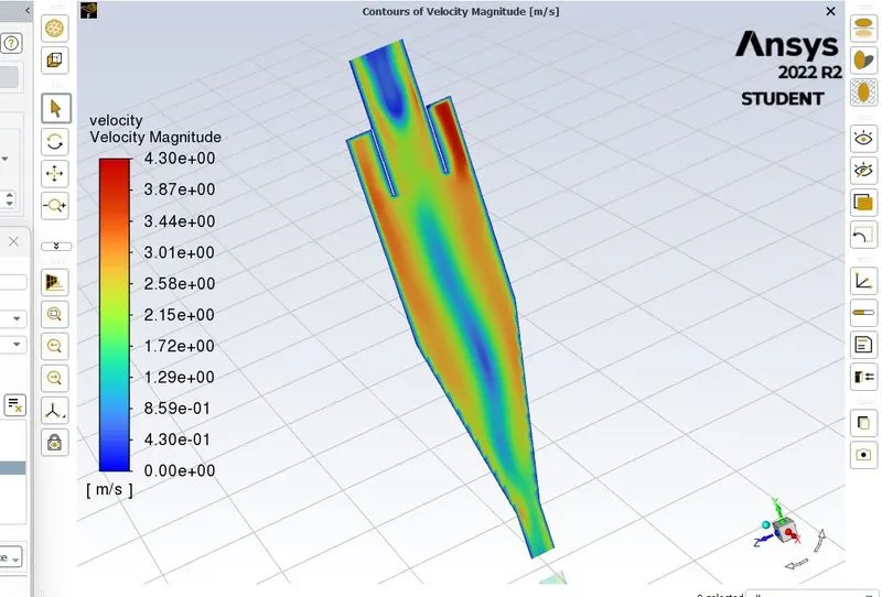
Results:
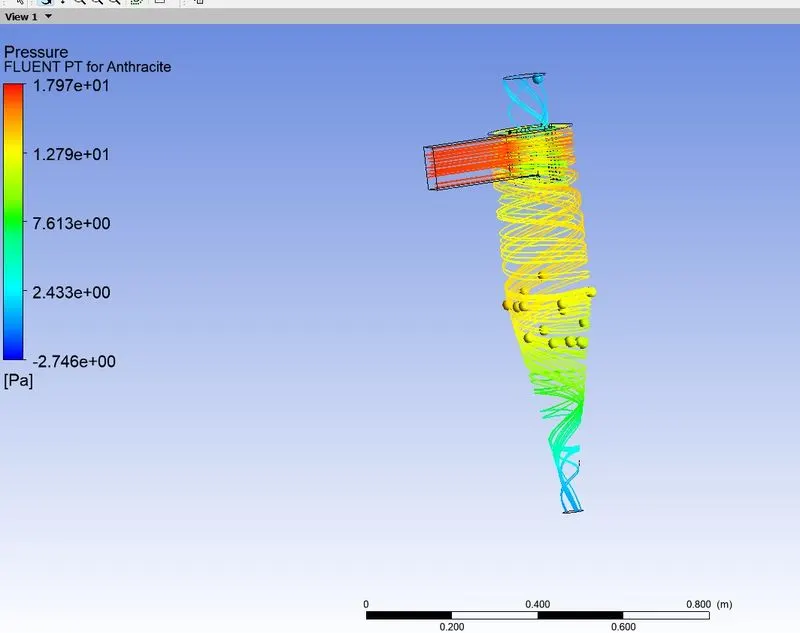
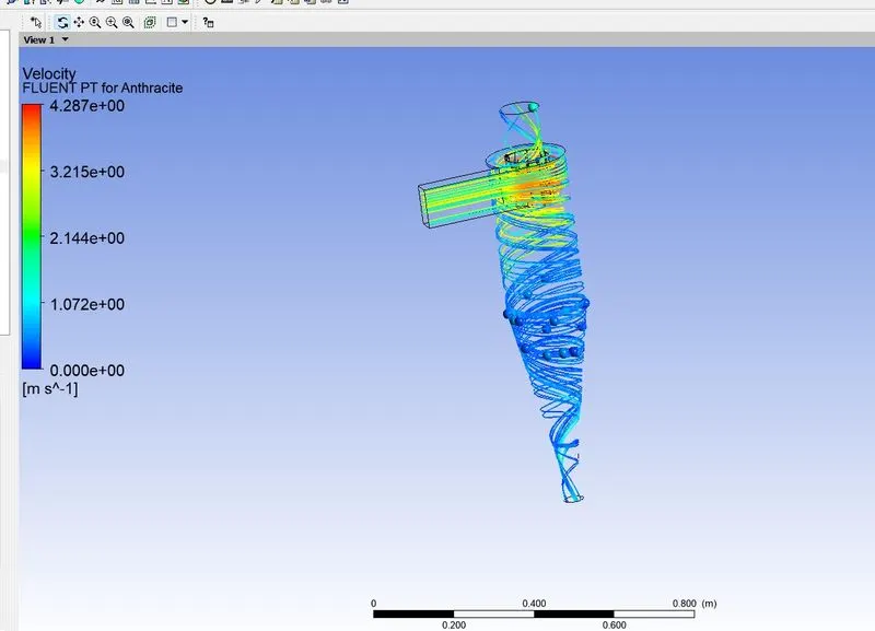
Case3:
pd=1e-6
pv=3
Mesh=6mm
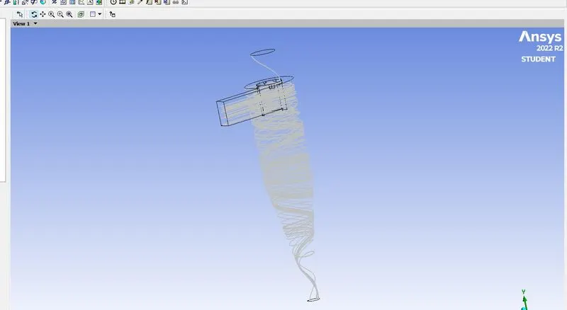
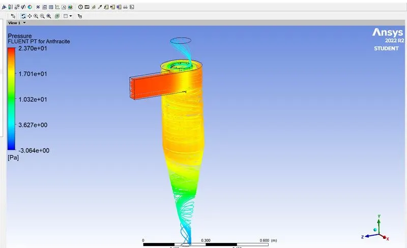
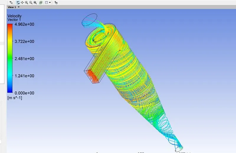
Case4:
pd=5e-6
pv=1m/sec
Mesh=6mm
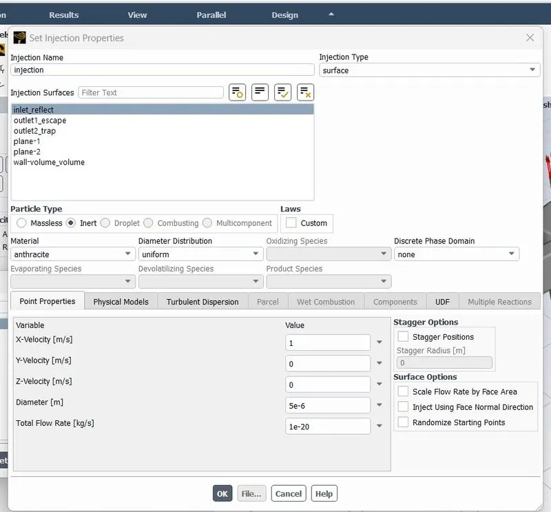
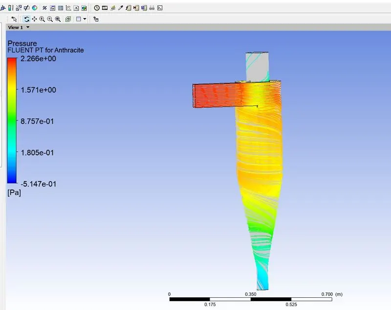
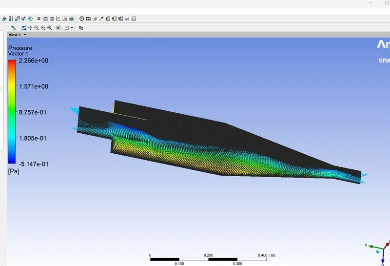
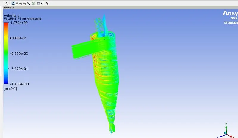
Case5:
pd=5e-6
pv=3m/sec
Mesh=8mm
Case6:
pd=5e-6
pv=5m/sec
Mesh=10mm
| s.no | Pd(particle dia) | Pv(particle velocity) | Ptracked | Ptrapped | effi=ptrapped/ptracked | pressure drop |
| 1 | 5 | 3 | 91 | 56 | 0.615384615 | -0.676 |
| 2 | 3 | 3 | 91 | 60 | 0.659340659 | -0.677 |
| 3 | 1 | 3 | 136 | 117 | 0.860294118 | -0.388 |
| 4 | 5 | 5 | 91 | 53 | 0.582417582 | -0.671 |
| 5 | 5 | 3 | 91 | 55 | 0.604395604 | -0.676 |
| 6 | 5 | 1 | 136 | 120 | 0.882352941 | -0.24 |
My Observation & conclusion
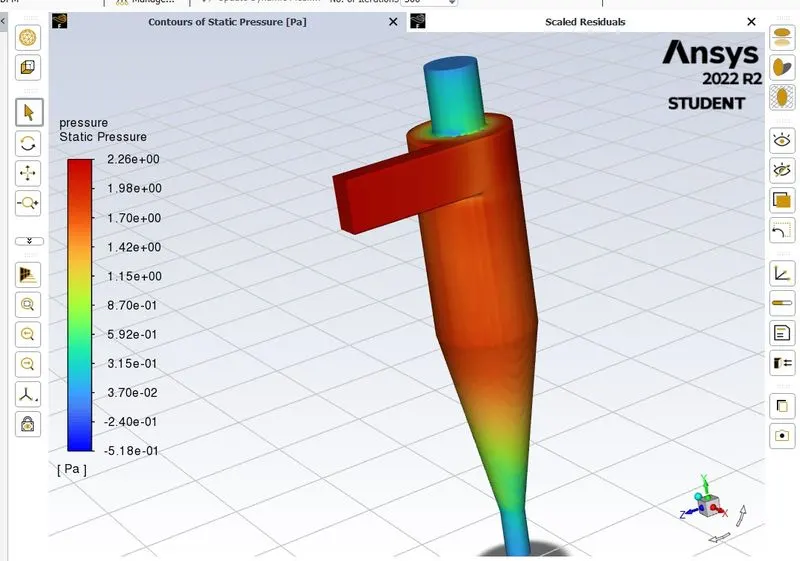
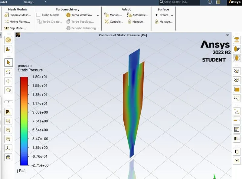
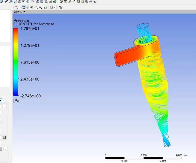
- The velocity of gas tranformed into confined vortex,if particle dia less, then trapped will more & efficiency will be more,there is large a pressure drop.
Pressure drop:
Pressure drop is defined as the difference in total pressure between two points of a fluid carrying network. A pressure drop occurs when frictional forces, caused by the resistance to flow, act on a fluid as it flows through the tube. The main determinants of resistance to fluid flow are fluid velocity through the pipe and fluid viscosity Pressure drop increases proportionally to the frictional shear forces within the piping network. A piping network containing a high relative rouhness rating as well as many pipe fittings and joints, tube convergence, divergence, turns, surface roughness, and other physical properties will affect the pressure drop. High flow velocities and/or high fluid viscosities result in a larger pressure drop across a section of pipe or a valve or elbow. Low velocity will result in lower or no pressure drop.