Week 8 - Simulating Cyclone separator with Discrete Phase Modelling
Aim:- To perform analysis on cyclone separator and calculate the separation efficiency and pressure drop.
Objective:-
- To write a few words about any four empirical models used to calculate the cyclone separator efficiency.
- To perform an analysis on a given cyclone separator model by varying the particle diameter from 1 μm to 5 μm and calculate the separation efficiency in each case. Discuss the results. [Use both the velocity's as 3m/sec.]
- To perform an analysis on a given cyclone separator model by varying the particle velocity from 1 m/sec to 5 m/sec and calculate the separation efficiency and pressure drop in each case. Discuss the results. [Use particle diameter size as 5 μm for all cases & keep flow velocity same as particle velocity]
Tools used :-
1) Space claim
Volume extract , Supress for physics
2) Ansys mesh
Method , element size
3) Ansys Fluent
Gravity , turbulence model , descrete phase , boundary condition , Surface intergral , Initialization , export
4) CFD-Post
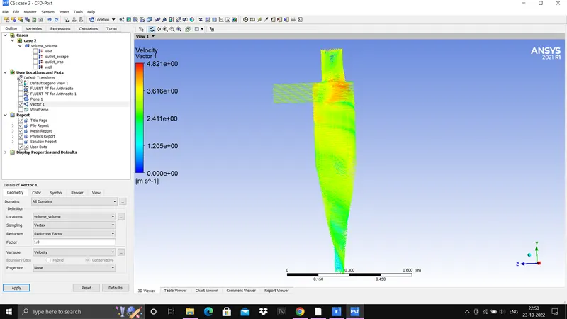
Velocity vector , contour
Theory :-
Cyclone separator
The cyclone separator is a device for separating solid particles from contaminated gas streams. It uses centrifugal force generated by a spinning gas stream to separate particles from the carrier gas. Their simple design, low capital cost and nearly
maintenance-free operation make them ideal for use as the removal of large particles for both air pollution control and removal of coal dust in a power plant and used as a spray dryer or gasification reactor. it has long been used in industrial applications such as power generations, gas turbines, chemical processes and so forth.
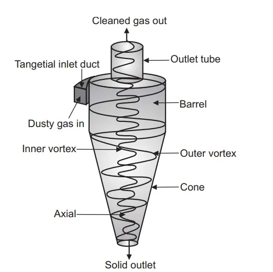
Two parameters are there for assessment of better design and performance of cyclone separator and they are
1) Collection efficiency
2) Pressure drop
Efficiency for cyclone separator is given by
efficiency = Particle trapped / Particle tracked
There are different empirical models used to calculate the cyclone separator efficiency
Iozia and Leith Model
Iozia and Leith Model, is developed based on force balance. The model assumes that a particle carried by the vortex endures
the influence of two forces: a centrifugal force and a flow resistance.
Li and Wang Model
The Li and Wang model includes particle bounce and turbulent diffusion at the cyclone wall. Li and Wang model was developed based on the following assumptions:
The radial particle velocity and the radial concentration profile are not constant for uncollected particles within the cyclone. The tangential velocity is related to the radius of cyclone by: uR^n = constant.
Koch and Licht Model
Koch and Licht Model recognized the inherently turbulent nature of cyclones and the distribution of gas residence times within the cyclone. Koch and Licht described particle motion in the entry and collection regions with the additional following assumptions:
• The tangential velocity of a particle is equal to the tangential velocity of the gas flow, i.e. there is no slip in the
tangential direction between the particle and the gas.
• The tangential velocity is related to the radius of cyclone by: uR^n = constant.
Lapple Model
Lapple Model was developed based on force balance without considering the flow resistance. Lapple assumed that a particle entering the cyclone is evenly distributed across the inlet opening. The particle that travels from inlet half width to the
wall in the cyclone is collected with 50% efficiency.
Procedure:-
1) Preprocessing
Geometry
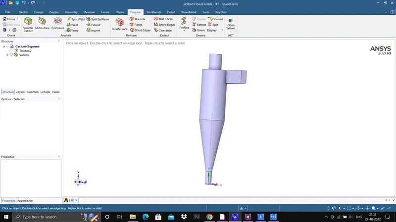
a) Open space-claim and import cyclone separator geometry
b) Extract the fluid volume using extract volume option
Meshing
a) Open ansys mesh
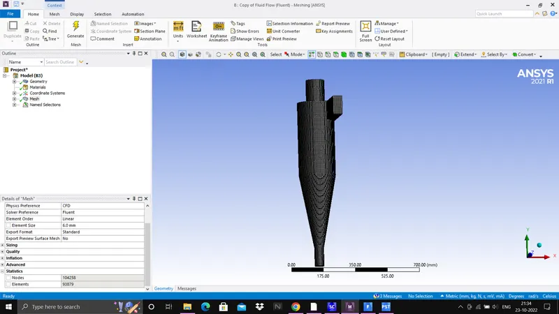
b) Here, structured mesh is used so select method
c) In method option select the geometry and give cartesian method
d) Give element size of 6mm and generate mesh and update
f) Create name selection as inlet , outlet escape , outlet trap , wall
2) Solving
Solver
a) Open ansys fluent solver
b) Here, pressure based solver with steady state condition is used for simulation
c) The turbulence model is k-epsilon with RNG is selected
d) This is a descrete phase modelling so enable DPM
e) In descrete phase, select inlet as surface for particle injection and Anthracite particle is used as particle.
f) Here, particle diameter will vary from 1micrometer to 5micrometer at same flow and particle velocity at 3m/s
g) Give boundary condition as
Inlet & wall - Reflect
Outlet escape - Escape
Outlet Trap - Trap
* Inlet velocity and particle velocity will be same and they vary from 1m/s to 5m/s
h) Due to variation in particle diameter and velocity there will be 5 cases which is
| Cases | particle diameter in micrometer | flow and particle velocity in m/s |
| Case 1 | 1 | 3 |
| case 2 | 3 | 3 |
| case 3 | 5 | 3 |
| case 4 | 5 | 1 |
| case 5 | 5 | 5 |
i) Initialize the simulation and iterate for 400 times
j) After convergence , note down number tracked, Escaped , trapped, incomplete
k) export the particle history data for postprocessing in cfd-post
3) Post processing
a) Import particle history data in CFD-Post
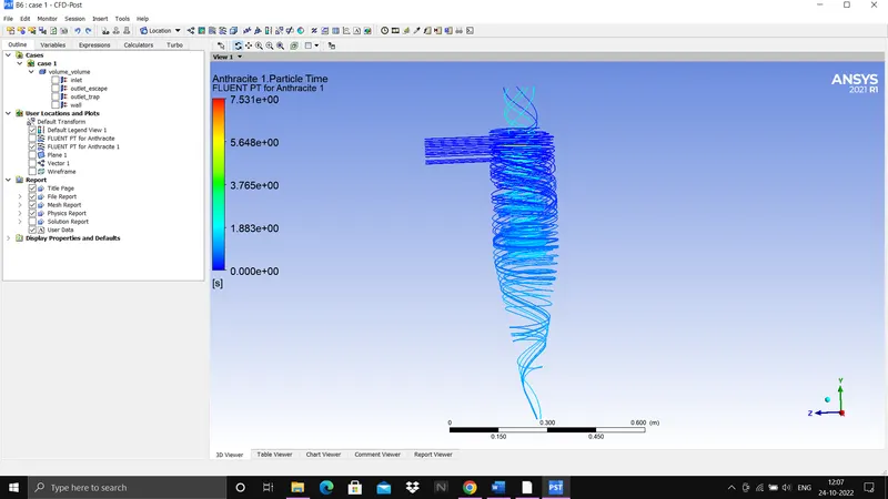
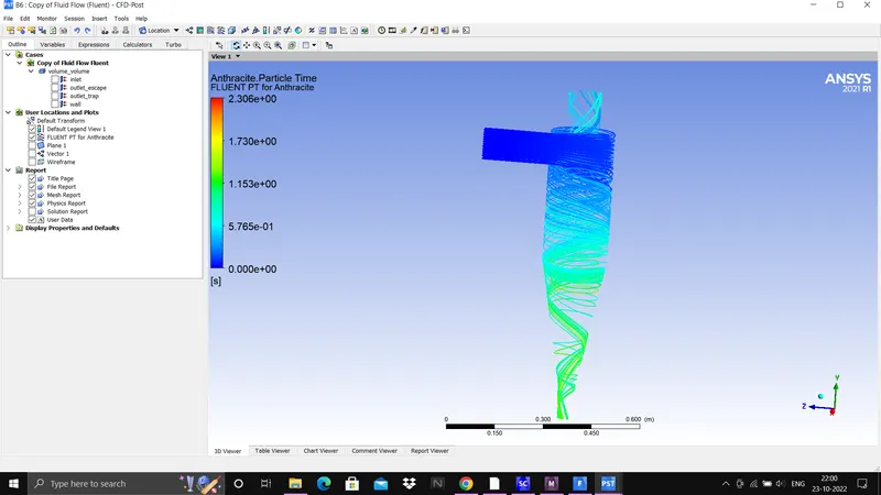
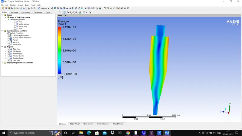
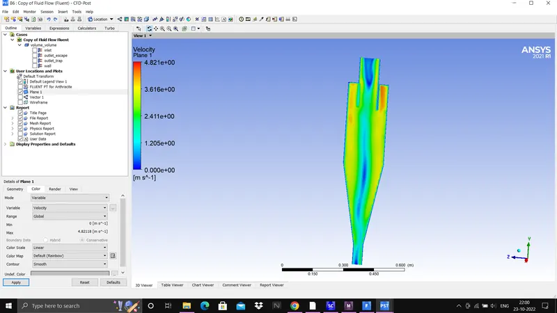
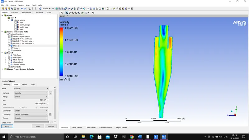
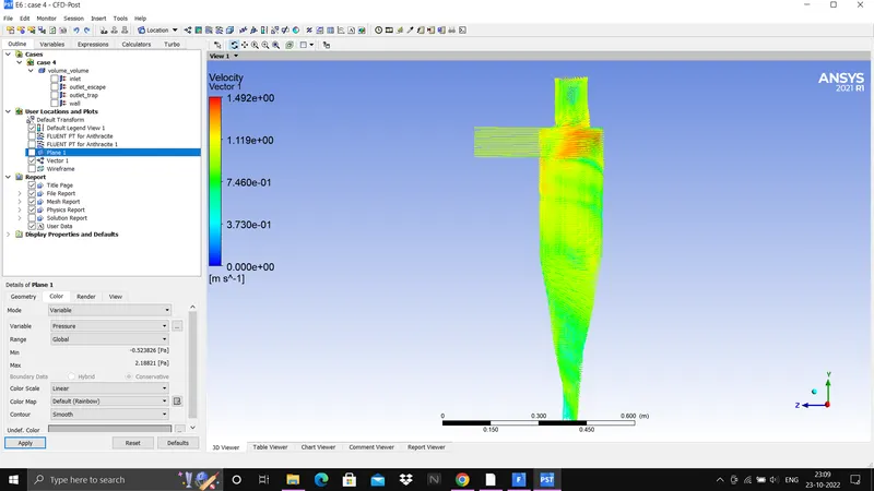
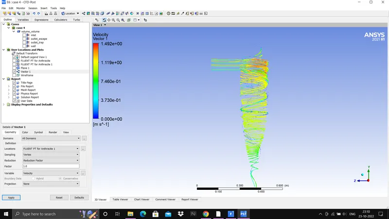
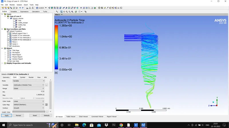
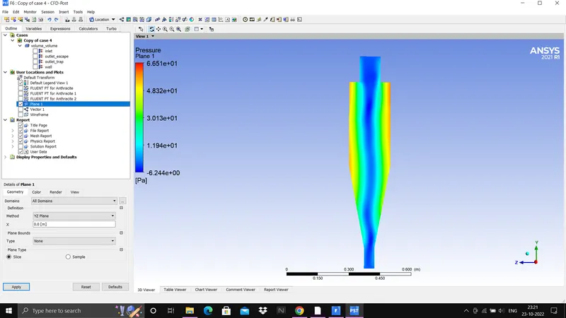
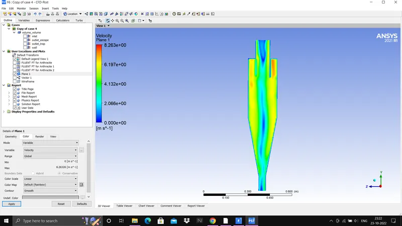
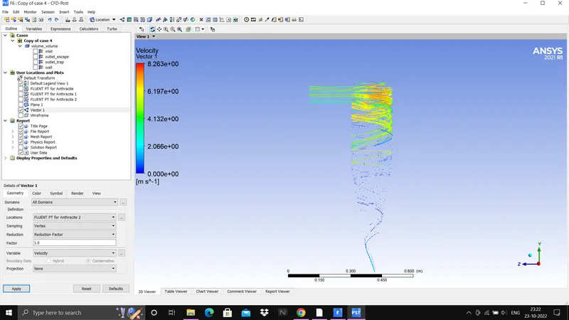
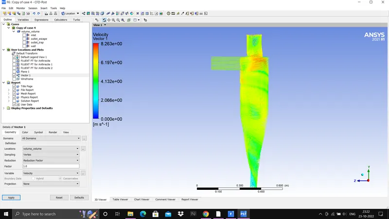
b) Plot contours for velocity, velocity vector ,pressure and anthracite particle time
Result:-
Efficiency and pressure difference for all the cases are tabulated below :-
Pressure difference = Total pressure at inlet - Total pressure at outlet escape
so,
Pressure difference 1 = 27.21 - 4.16 = 23.05 pa
pressure difference 2 = 27.21 - 4.16 = 23.05 pa
pressure difference 3 = 27.21 - 4.16 = 23.05 pa
pressure difference 4 = 2.73 - 0.38 = 2.35 pa
pressure difference 5 = 78.46 - 12.18 = 66.28 pa
| Cases |
Particle size (micrometer) |
Particle & flow velocity(m/s) | Particle tracked | Particle Escaped | Particle trapped | Particle incomplete | Efficiency | pressure difference (pa) |
| case 1 | 1 | 3 | 136 | 38 | 77 | 21 | 56.6 | 23.05 |
| case 2 | 3 | 3 | 136 | 20 | 105 | 11 | 77.2 | 23.05 |
| case 3 | 5 | 3 | 136 | 18 | 118 | 0 | 86.7 | 23.05 |
| case 4 | 5 | 1 | 136 | 21 | 16 | 99 | 11.7 | 2.35 |
| case 5 | 5 | 5 | 136 | 16 | 120 | 0 | 88.2 | 66.28 |
Contours :-
Case 1
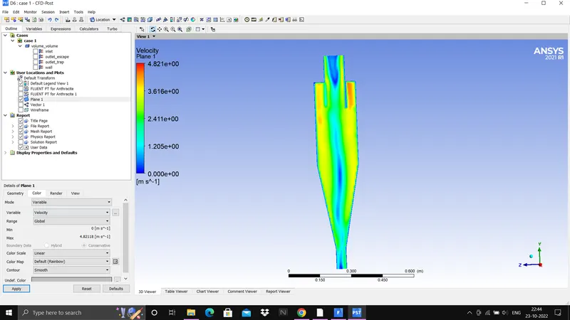
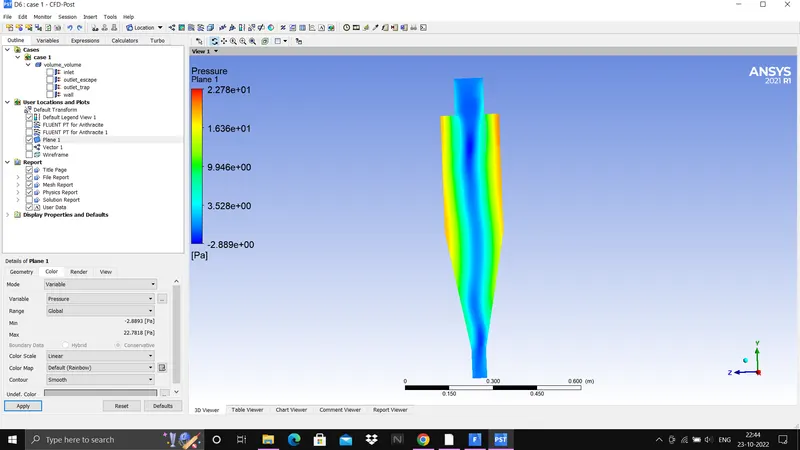
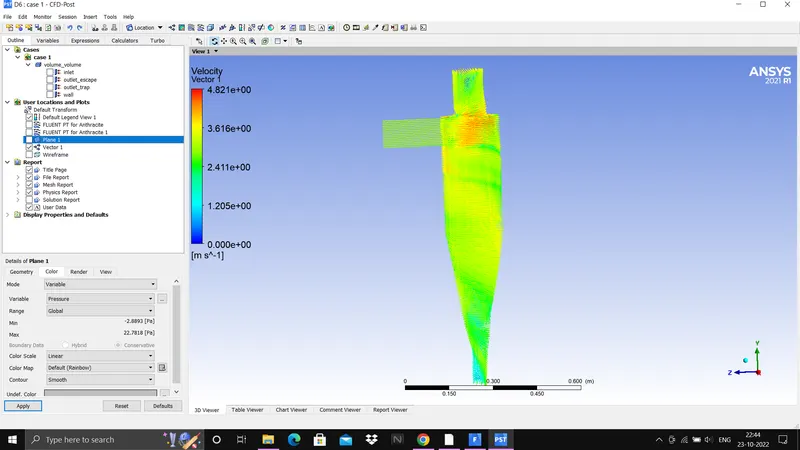
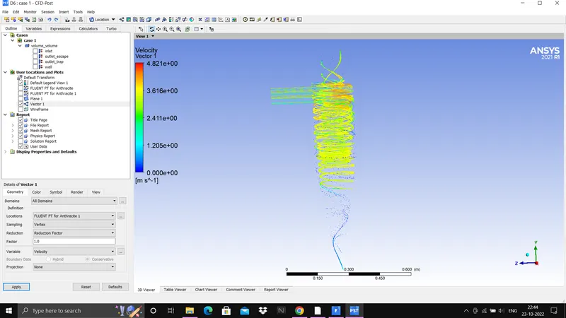
Case 2
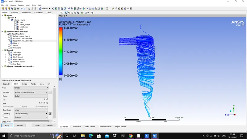
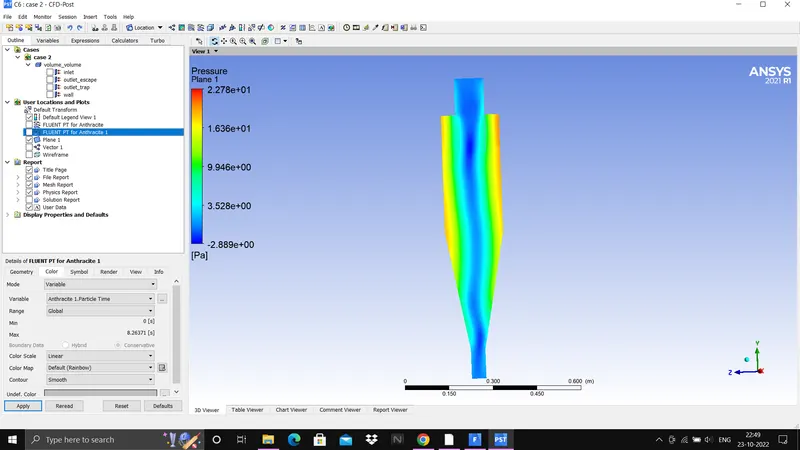
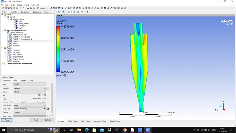
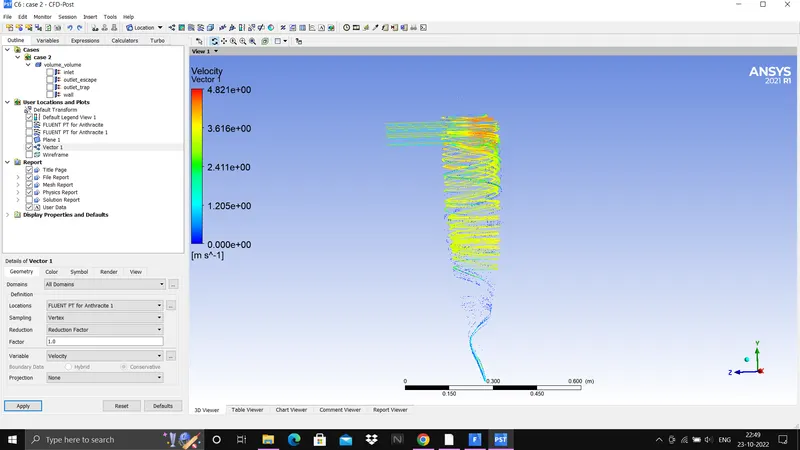
Case 3
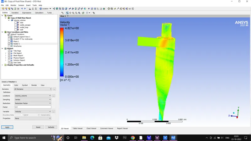
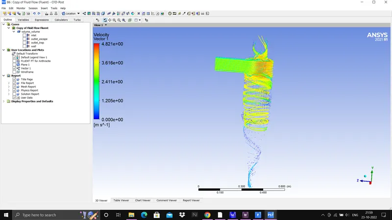
Case 4
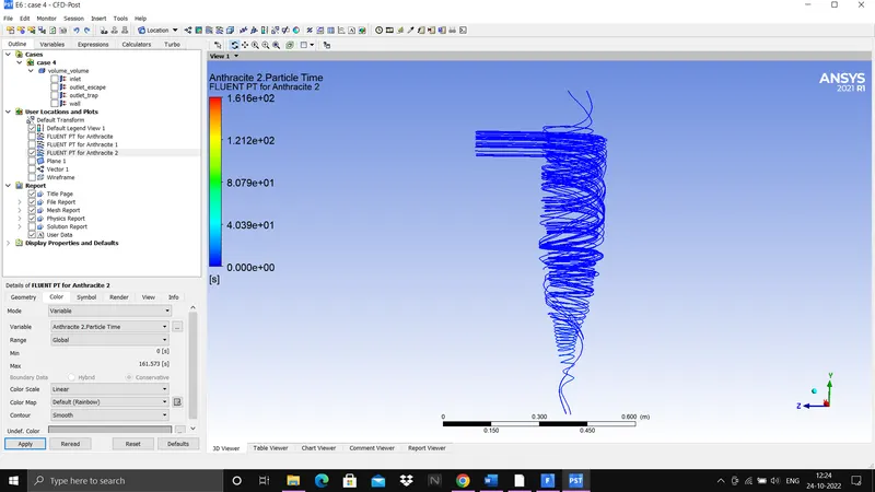
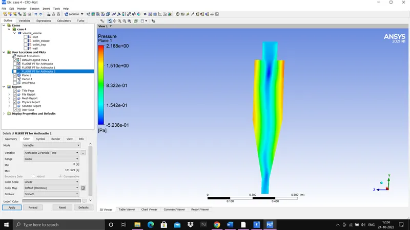
Case 5
Conclusion:-
Simulation on cyclone separator with discrete phase modelling has been done with different particle diameter with same particle and flow velocity Also with constant particle diameter and different particle and flow velocity .And cyclone efficiency and pressure drop at each case has been calculated which is tabulated above.
from calculated value it is observed that pressure difference at inlet and outlet escape is same but efficiency is increasing with increase in particle size. And when particle size remain constant and velocity is varied there pressure difference and efficiency both are increasing with increase in velocity.
Hence, it has been seen that particle size of 5 micrometer and at 5m/s flow & particle velocity gives maximum efficiency and pressure difference.
Reference:-