Week 8 - Simulating Cyclone separator with Discrete Phase Modelling
AIM:
To perform analysis on cyclone separator and calculate the separation efficiency and pressure drop.
OBJECTIVE:
- To write a few words about any four empirical models used to calculate the cyclone separator efficiency.
- To perform an analysis on a given cyclone separator model by varying the particle diameter from 1 μm to 5 μm and calculate the separation efficiency in each case. Discuss the results. [Use both the velocity's as 3m/sec.]
- To perform an analysis on a given cyclone separator model by varying the particle velocity from 1 m/sec to 5 m/sec and calculate the separation efficiency and pressure drop in each case. Discuss the results. [Use particle diameter size as 5 μm for all cases & keep flow velocity same as particle velocity]
BOUNDARY CONDITIONS:
Inlet and wall:- Reflect
Outlet(Top):- Escape
Outlet(Bottom/dustbin) - Trap
INTRODUCTION:
Cyclone seperator is a means of separating different liquid phases (different liquid densities), or, separating particles from a gas stream.
Cyclone separators often form part of a pre-cleaning stage prior to a gas or liquid being discharged. This article focuses on the gas cyclone separator.
Gas cyclone separators are grouped into two main categories, reverse-flow and axial-flow.
Reverse flow cyclone separators are cone shaped. Gas enters the top of the separator body, flows downwards, then flows back upwards and is discharged.
For axial flow (a.k.a. straight through) cyclone separators, gas enters at one end and is discharged at the opposite end. Axial flow separators are not as common as reverse flow separators.
Efficiency
The term collection efficiency, or simply ‘efficiency’ throughout the article. The collection efficiency -also known as the capture or recovery rate- is a measurement of a cyclone’s ability to separate particles from the flowing gas stream.
Because particles have different sizes, the efficiency rating is usually given for varying particle sizes.
cyclone separator is an industrial assembly with no moving parts and a simple design.
Effectiveness. Cyclone separators are generally able to remove somewhere between 50-99% of all particulate matter in flue gas.
Empirical models for Cyclone Separator Efficiency:
- Iozia and Leith Model
- Li and Wang Model
- Koch and Licht Model
- Lapple Model.
|
Advantages |
Disadvantages |
|
|
|
|
|
|
|
|
|
Methodology:
There are two different Phases as given below:
- Continuous Phase
- Discrete Phase
INTRODUCTION:
DPM - Discrete phase modelling used for this stimulation.
In this DPM is has 2 pahses.(2phase, 1-continous, 1-Discrete).
Continous - fluid, Discrete - dust.
by using this simulation the cyclone seperator is simulated.
ANSYS:
The CHT analysis of the graphics card is carried out in the ansys workbench with the help of the fluid flow (fluent).
The fluid flow simulations contains several steps are :
1.geometry
2.Meshing
3.Setup
4.Solution
5.Results.
By the help of all this software the DPM anaysis is analysied properly and completely.
GEOMETRY:
Ansys fluent - geometery - open spaceclaim - model is opened in the spaceclaim.
Prepare - extract volume - edges - select.
select the inlet,outlet at top and outlet at bottom,then click ok.
then the volume extraction is completed.
now,the body or the model except the volume.the other parts are suppress for physics.
after doing all this the geometry is saved and the space claim is closed.
MESHING:
The model is uploaded in the ansys workbench. then the meshing is opened.
the name selection is carried out as:
inlet, outlet-1(top) , outlet-2(bottom).
change the mesh size as 10 mm.
and use the pinch adjust .
then the meshed model is shown below:
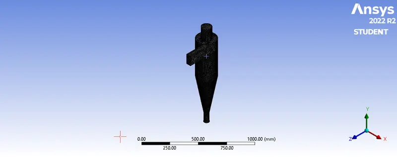
finally,the meshed model is updated in the ansys workbench.
SETUP:
the setup is opened with the double precisoin and the 4 solver.
the meshed dispalyed in the fluent is :
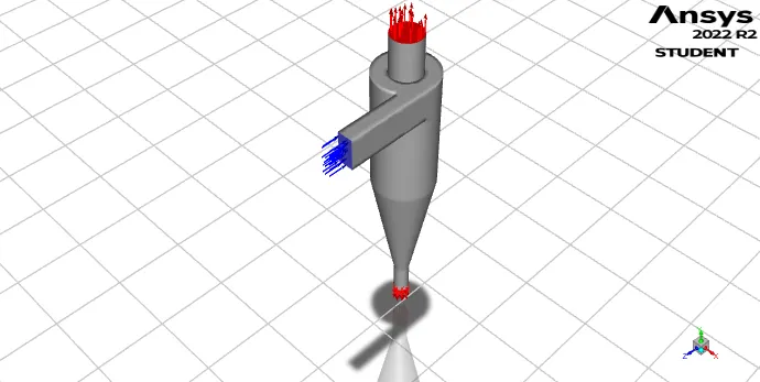
the steady sate solver is used.
gravity is enabled and give the value as -9.81 in y direction.
viscous - k-epsilon - RNG - swirl dominated flow.
discrete phase model - interact with continuous phase (click that) - update DPM source flow iteration.
in the tracking - 50000 steps. and the step length factor is 5.
click injection - create - inert - anthracite - injection type as surface. - inlet - click ok.
x-velocity as 3m/s. and diameter as 5e-06 and click ok.
now the boundary conditions are applied as,
the inlet- edit - velocity magnitude as 3m/s. and DPM as reflect and click ok.
in the solution deck, methods- turbulent kinetic energy set as second order upwind.
and also the same deck, turbulent dissipation rate is set as the second order upwind.
now, in the solution deck -use standard intialization.
oprions - compute from (inlet) and click intialize.
now the ietration is set as 600 and calculate.
CASE 1:
VELOCITY =3M/S & DIAMETER = 5 μm .
then the residual of the cyclone seperateor is :
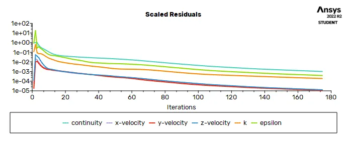
finally the file - export - particle history data -injection-0 -browse the location to save and click on write.
then the data about the cyclone seperator is stored in the saved location .
RESULT:
After the model is uploaded in the ansys workbench the result opened . then the CFD post is opened.
result - file - import - particle fluent - click ok.
then the cyclone seperator is reduce the transparency as 0.75 .
then the cyclone seperator velocity is shown below:
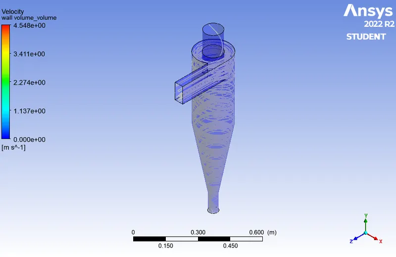
in the antractie particle time - variable - apply.
then the antractie particle time is shown below is :
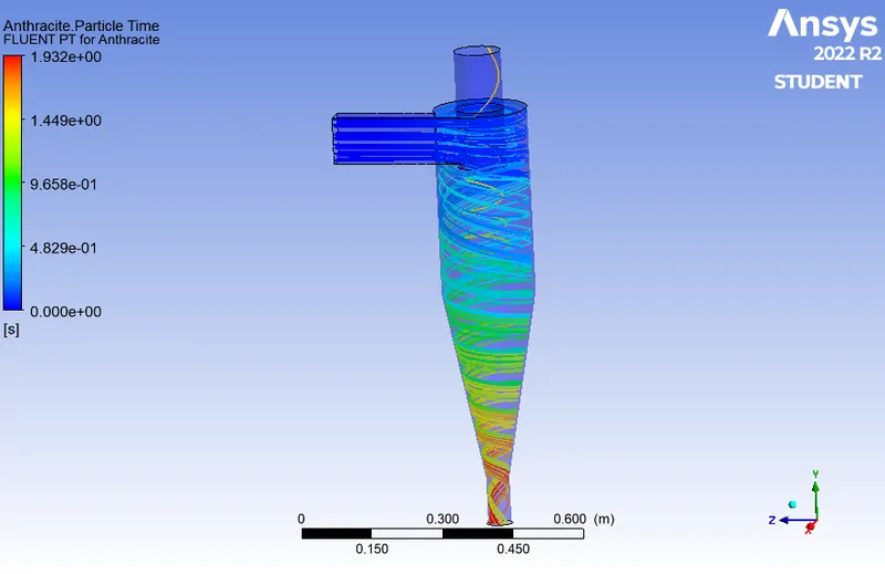
insert - vortex - vortex core region - click ok .
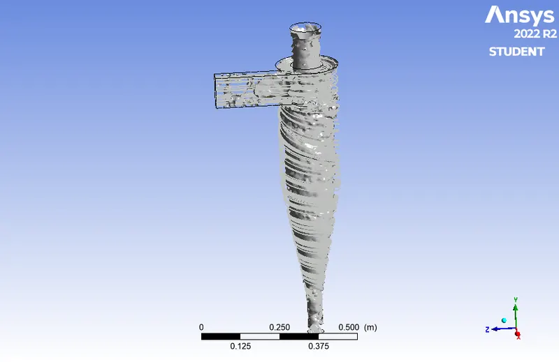
put the swriling strength as 0.25 and apply.
Separation efficiency=124/124*100=100%.
the vortex core is shown.
animation - fluent particle for anthracite - save - particle tack -save movie - mpeg4 and repeat as 1 and play.
then the animation is saved .
in the calculation tab the calculations like the mass flow rate through the inlet and he outlet is easily identified.
by this way the cyclone seperator simulation is carried out succesfully and properly.
CASE 2:
VELOCITY =3M/S & DIAMETER = 3 μm .
then the residual of the cyclone seperator is :
then the antractie particle time is shown below is :
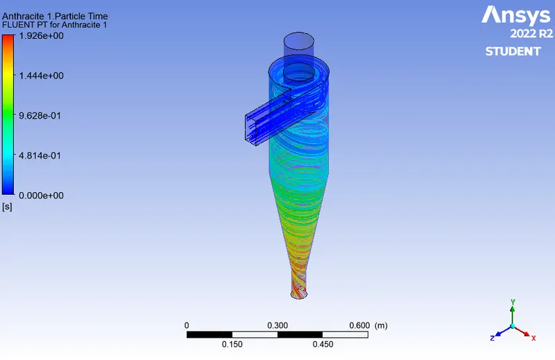
THE PRESSURE of the antracite particle time:
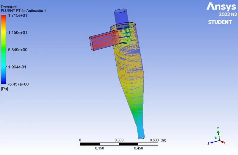
Separation efficiency=106/124*100=86.38%
CASE 3:
VELOCITY =1M/S & DIAMETER = 5 μm .
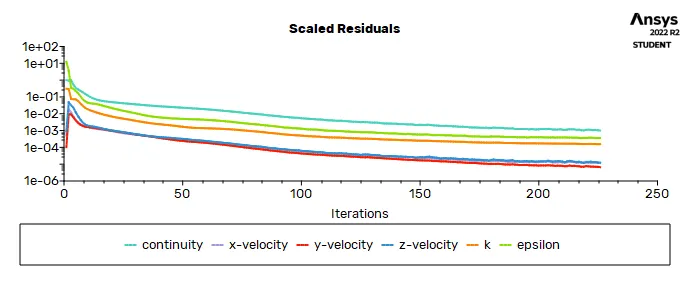
then the residual of the cyclone seperator is :
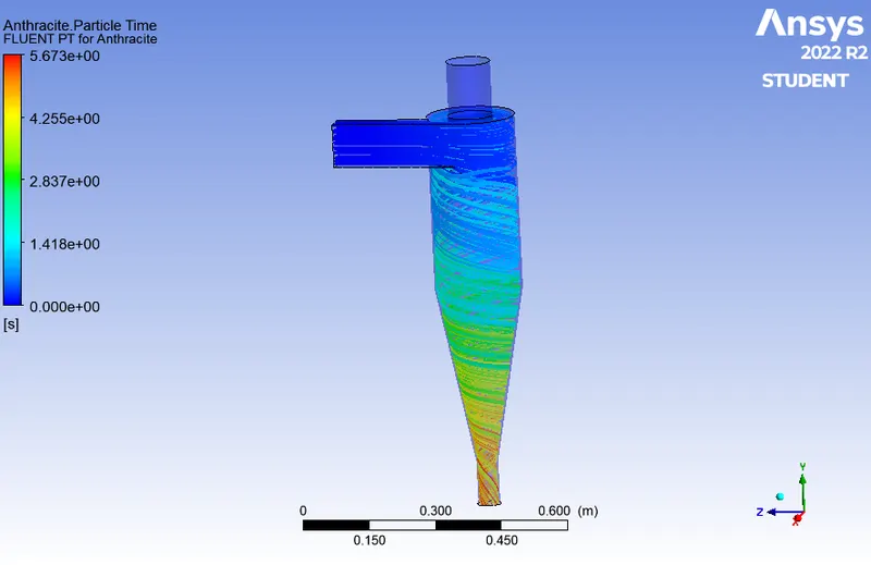
then the antractie particle time is shown below is :
THE PRESSURE of the antracite particle time:
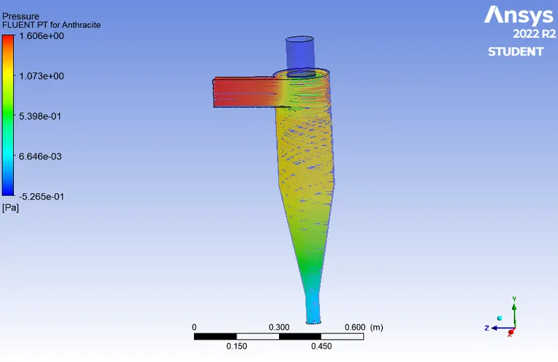
Separation efficiency=11/124*100=8.8%
Pressure drop=inlet-outlet=1.69-0=1.69 Pa.
CASE 4:
VELOCITY =5M/S & DIAMETER = 5 μm .
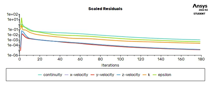
then the residual of the cyclone seperator is :
then the antractie particle time is shown below is :
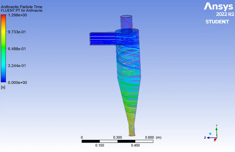
THE PRESSURE of the antracite particle time:
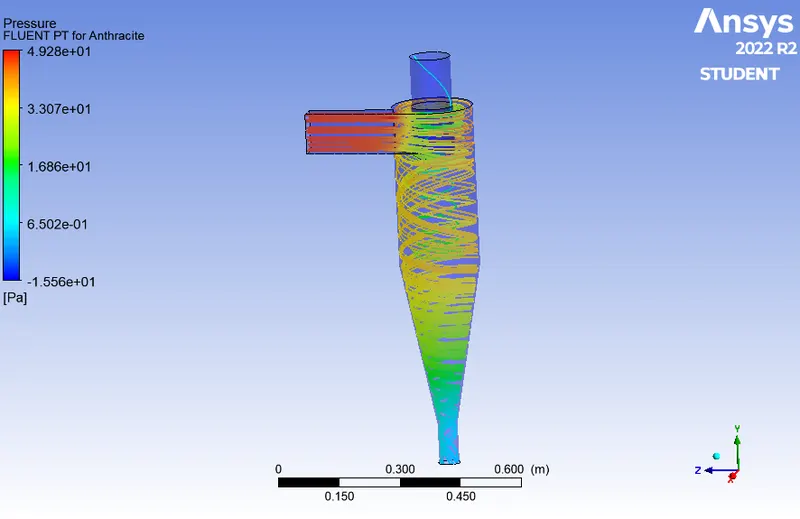
Separation efficiency=124/124*100=100%
Pressure drop=inlet-outlet=52.49-(-0.014)=52.504pa.
SEPERATION EFFICIENCY:
It can be defined as ratio of number of particles within given size limit collected at drip to number of particles entered in separator.
Separation efficiency=Number of particles trapped/number of particles tracked.
PRESSURE DROP:
Pressure drop is the amount of flow resistance the cyclone will create in the system. Pressure drop is usually measured in units of inches of water column (in WC) or Pascals (Pa). Pressure drop is a function of flow rate, gas density, and cyclone design.
Finally the simulation of the CYCLONE SEPERATOR is carried out succesfully and properly.