Week 8 - Simulating Cyclone separator with Discrete Phase Modelling
AIM- To simulate flow of cyclone seprator and showing result for different particle size(1, 3, 5 micron) and different velocity(1,3,5 m/s).
Theory
Cyclone seprator
cyclones seprators are sepration devices that use the principle of inertia to remove particular matter from gases.Cyclone seprators is one of many air pollution removal technology known as precleaners as they remove larger pieces of matter from fuids(gases)
This prevents finer filterationmethods from having to deal with large,more abrasive particles later on.In addition,several cyclone seprators can operate in parallel system known as multicyclone
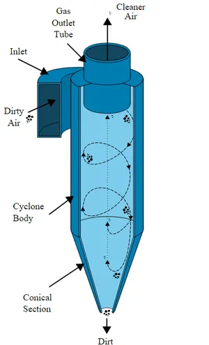
Cyclone sperator work much like centrifuge, but with a continuous feed of dirty air. In a cyclone seprator,dirty gases is fed into a chamber the inside of a chamber creates a spiral vortex similar to tornado .This spiral fomation and sepration on bases or heavy and lighter components of gas, The lighter components of gas have less inertia so it is influenced by vortex forces which leads them to upwrads in escape outlet ,but heavier components have more inertia so the travels downard to trap outlet.
Since these larger particles have difficulty following the high speed spiral motion of gas and vortex,the particles hit the inside walls of container and drop down towards trap outlet. These chambers are shaped like an upside -down cone to promote the collection of these particles at the bottom of container.The cleaned gases escapes out the top of chamber.
In general there arre 4 models used to calculate cyclone seprator efficiency:
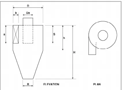
1. lozia and leith model(1990)
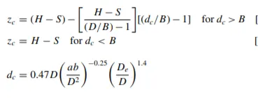
This logistic model is a modified version of Barth(1956) model which is developed based on force balance. The model assumes that a particle carried by the vortex endures the influence of two forces: A Centrifugal Force (Z) and flow of resistance(W). Core length(zc),and core diameter(dc) are given as
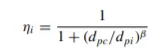
`beta` is an expression for slope parameter derived based on th statistical analysis of experimental data of cyclone with D= 170
0.25 m given as :

and dpc is the 50% cut size given by barth:
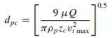
where core length ZC and core diameter are given as
2. Li and wang model
This model includes a prticle bounce or reentrainment and turbulent diffusion at the cyclone wall . A 2 dimensional analytical expression of particle distribution in cyclone is obtained on folowing assumption:
The radial particle velocity and radial concentration profile are not constant for uncollected particles in cyclone.
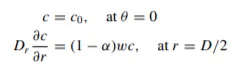
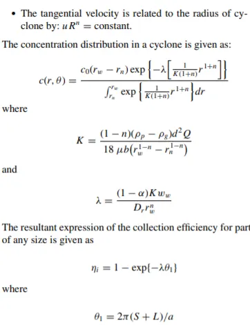
Boundary conditions with the consideration of turbulent diffusion coeffiecient particle bounce reentrainment on the cyclone wall
Those conditions are:
3. Koch and lIcht model
This theory inherently is turbulent nature of cyclones and distribution of gas residences times within cyclone.Koch and Licht described particle motion in the entry and collectionregions with the additional following assumptions:
The tangential velocity of a particle is equal to tangential velocity of gas flow.
The tangential velocity is related to radius of yccloneby Rn= constant.
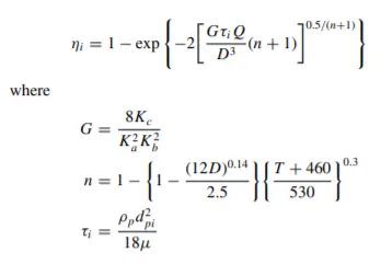
A force balance and and equation on the particles collection yields the grade efficiency `ηi`
4. Lapple model
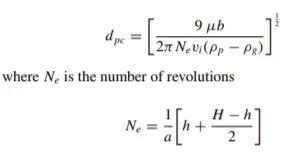
This model was based on force balance without considering the flow resistance.Lapple assumed that particle entering the cyclone is evently disturbed across th inelt opening. The particle taht travels form inlet jhalf width to the wall in cyclone is collected with 50 % efficiency The semiemperical realtioship developed by lapple to calculate a 50% cut diameter,dpc is:
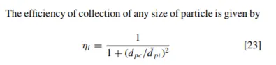
The collection efficiency of cyclones varies as a function of density,particle size and cyclone design. Cyclone efficiency will generally incrase with increase of particle size, inlet duct velocity,body length,no. of gas revolutions in cyclone, ration of cyclone body diameter to gas exit diameter,smoothness of inner wall etc.
Similarly efficiency will decrease with inscrease in vscosity,cyclone body diameter,gas exit diameter etc.
The efficiency of cyclone collector is related to pressure drop across the collector.This is an indirect measure of energyrequired to move the gas though system. the pressure drop is a function of inlet velocity and cyclone diameter.
Steps for solving
- Firstly we import geometry in spaceclaim and extract volumes selcting edges.
- Then we supprress outer body for physics and open body in mesh.
- We create cartesian mesh for 5 mm and open in solver.
- In solver we use Steady state, pressure based, k-epsiolon model(RNG) with gravity on for y axis .
- The we inset the discrte phase model and create injections for particles for different velosity and size.
- We give boundary conditions accordingly to injections,
- At last we initialise and solve for 300 iteration.
Solving with visual medium
Geometry
we open in space claim and extract volume 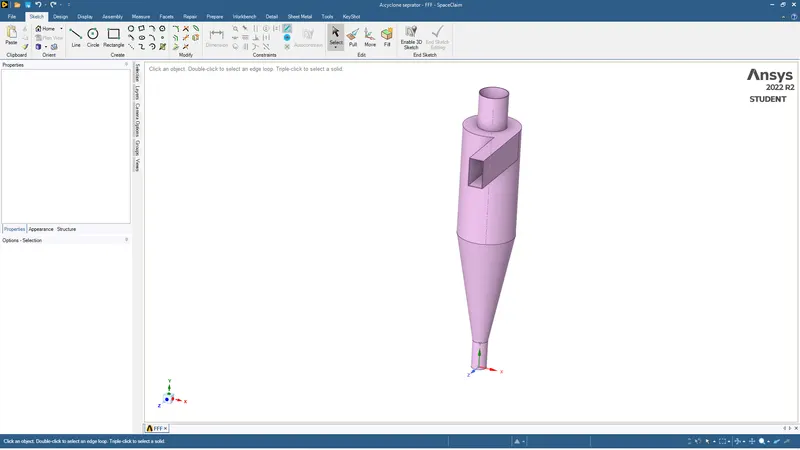
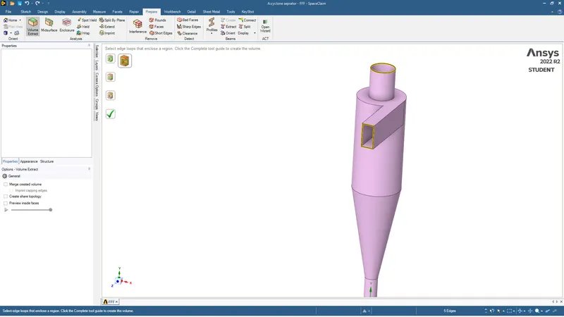
After this we supress for physics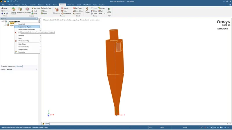
Then we open this in mesh
MESH
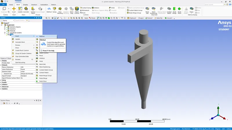
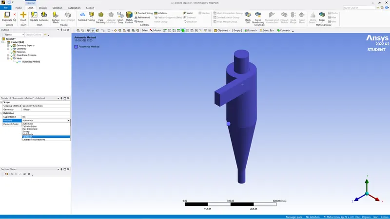
We open geometry and use cartesian method for creating mesh
Then we create mesh for 5mm 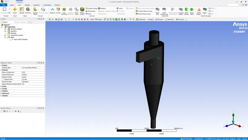
Then we give name to faces using anme selection( Inlet,outlet-escape,outlet-trap)
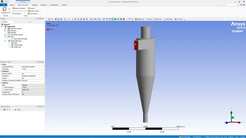
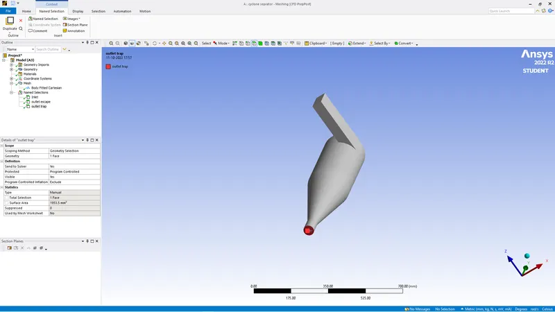
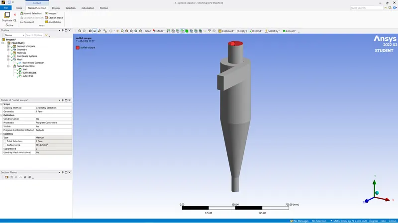
Then we open model in solve ANSYS FLUENT
SOLVE
First we give general setting with pressure based model, staedy state and k- epsilon model (RNG) with gravity on -9.81 (-) because of forces acting at opposite of y axis.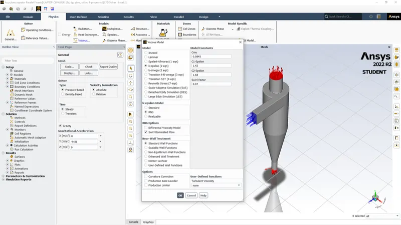
Then we use discrete phase modle and create injections for creating particle for different sizes and velocity at inlet.
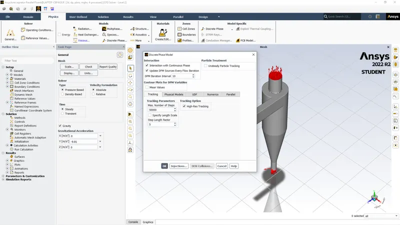
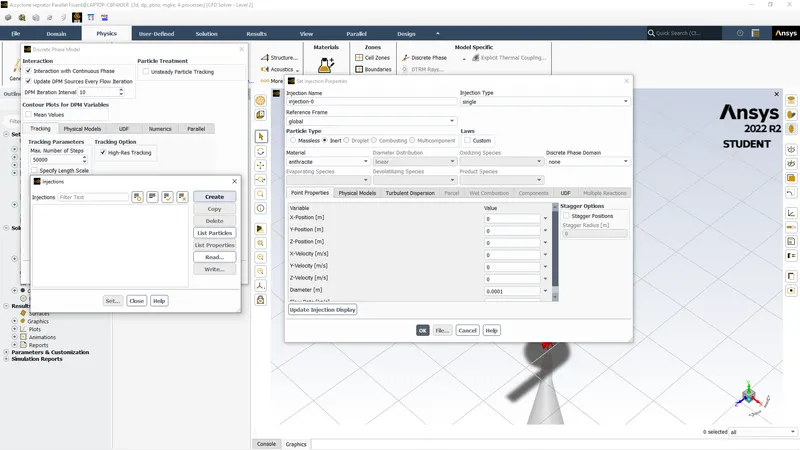
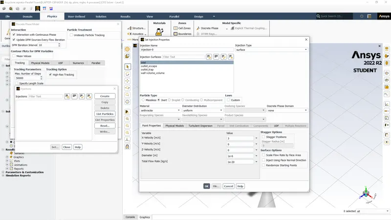
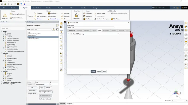
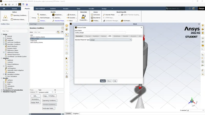
After assigning data for injections we give boundary conditions at inlet, outlet trap and outlet escape
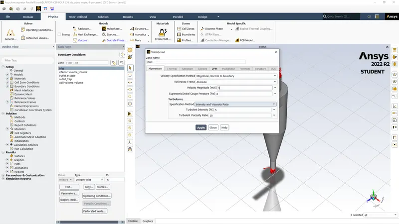
For inlet we give DPM condition as reflect if we dont do that the particles will escape from inlet itself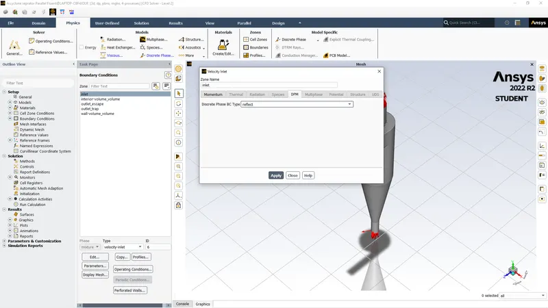
We give escape outlet = escape in DPM & Trap outlet = trap as boundary condition
Then we give wall DPM conditions = reflect
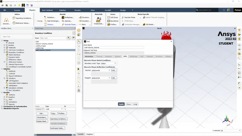
Then we initialize with inlet and run for 300 iteration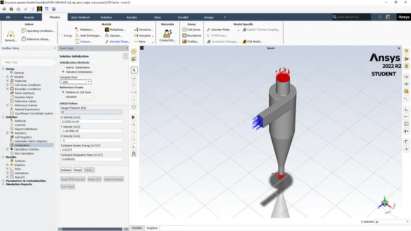
RESULT
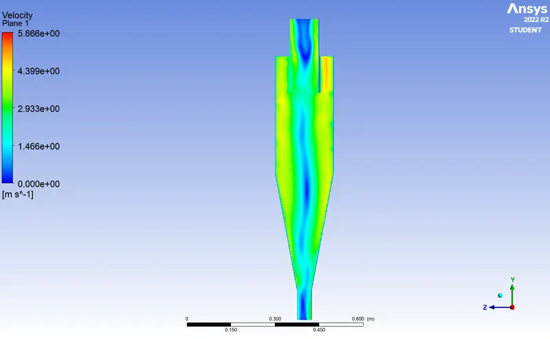
CASE-1 (Particle dia= 1`mum`& velocity = 3m/s)
Residual
velocity contour
Pressure contour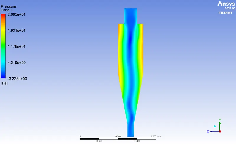
No. of particles= 378, escaped= 75, Trapped= 303
Efficiency = 303/378 = .80 (80%)
pressure drop = inlet pressure - outlet pressure
= 31.33- 4.30 = 27.03 Pa
Link for animation= https://drive.google.com/file/d/1NrU75dbcn9Acf0fg13Kfa75oecG97CAP/view?usp=sharing
CASE-2 ( Particle dia= 3`mum` & velocity = 3m/s)
Residual
Velocity contour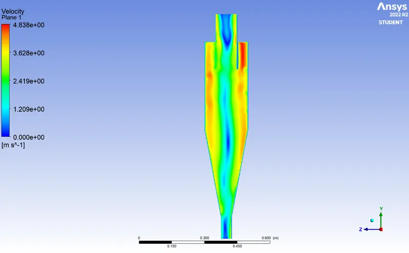
Pressure contour
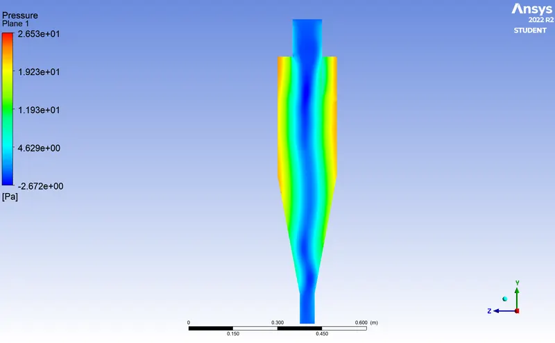
No. of particles= 378, escaped= 71, Trapped= 307
Efficiency = 307/378 = .812(81%)
pressure drop = inlet pressure - outlet pressure
= 31.33- 4.30 = 27.03 Pa
Link for animation:-https://drive.google.com/file/d/128omTONXgoh8W10wOFwfzW48Ee0GjZ3p/view?usp=sharing
CASE-3 ( Particle dia= 5`mum` & velocity = 3m/s)
Residual
Velocity contour
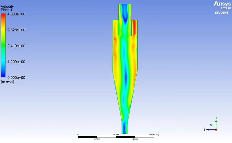
Pressure contour
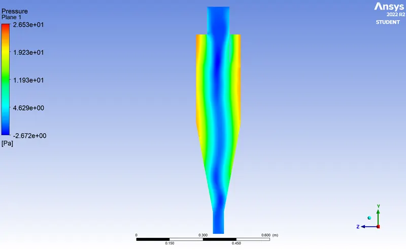
No. of particles= 378, escaped= 134, Trapped= 244
Efficiency = 244/378 = .64(64%)
pressure drop = inlet pressure - outlet pressure
= 31.33- 4.30 = 27.03 Pa
link for animation--https://drive.google.com/file/d/1M3oczBqVMneg4ikfNuUQU6L9VYfuyjvn/view?usp=sharing
CASE- 4( Partical dia= 5`mum` & velocity = 1m/s)
residuals
Velocity contours
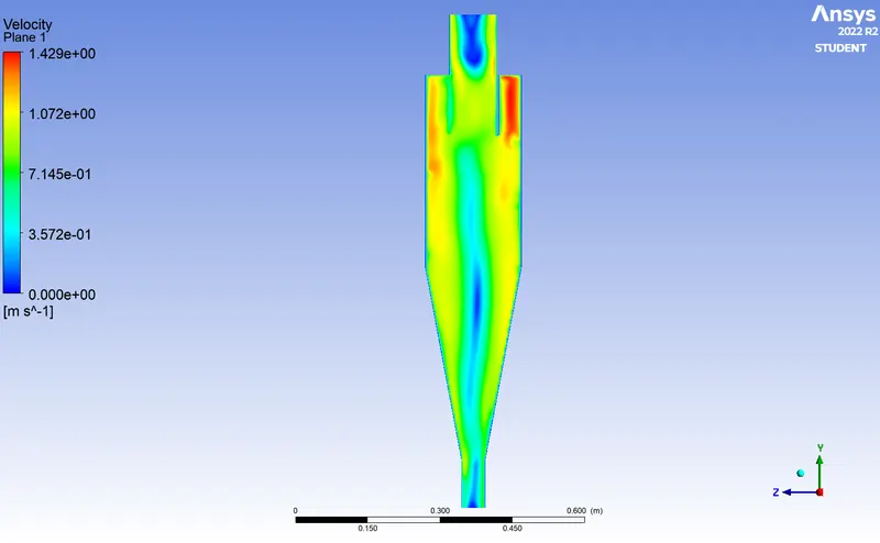
Pressure contour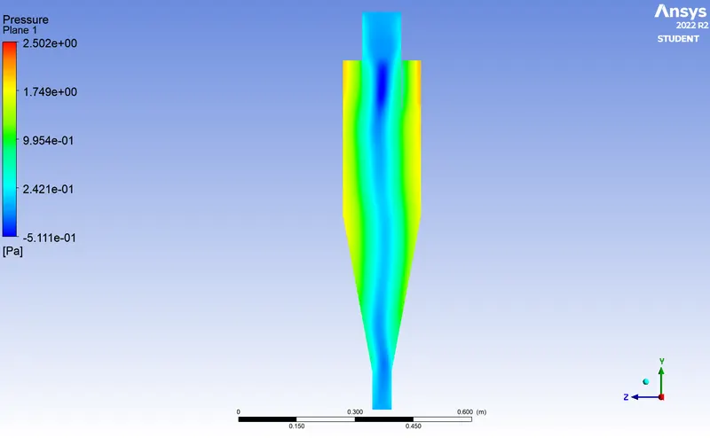
No. of particles= 378, escaped= 66, Trapped= 312
Efficiency = 312/378 = .825(82.5%)
pressure drop = inlet pressure - outlet pressure
= 2.87 - 0.37 = 2.50 Pa
link for animation:-https://drive.google.com/file/d/1XFsKZWs1fJm1skWE_062ADx8AyaKOnqK/view?usp=sharing
CASE-5 ( Partical dia= 5`mum` & velocity 5m/s)
Residual
Velocity contour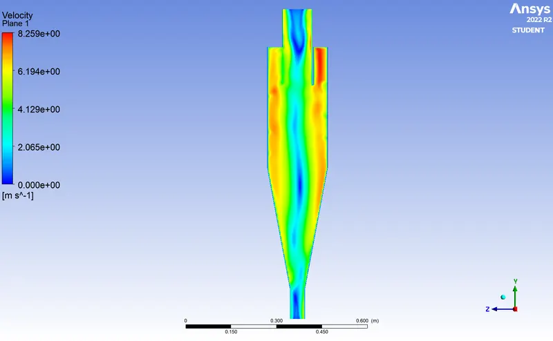
Pressure contour
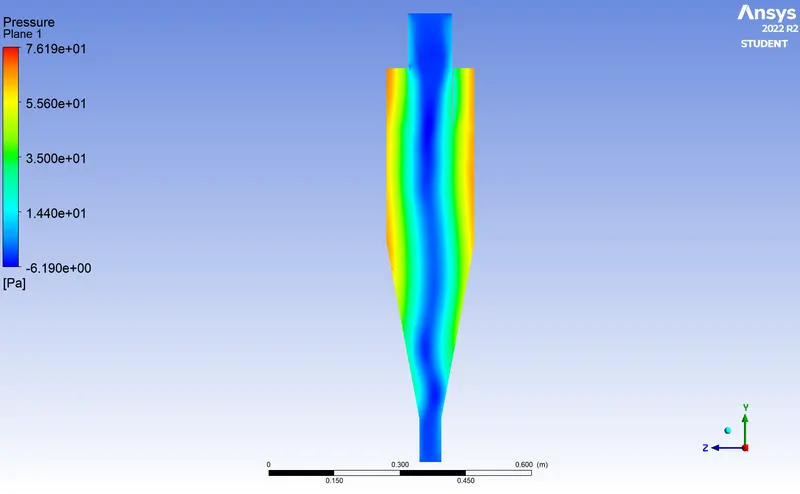
No. of particles= 378, escaped= 74, Trapped= 281, incomplete= 23
Efficiency = 281/378 = .74(74%)
pressure drop = inlet pressure - outlet pressure
= 90.83 - 12.58 = 77.73 Pa
Link for animation:-https://drive.google.com/file/d/1NQ51OktbShfLKS24V9Es5t956sdJecKG/view?usp=sharing
CONCLUSION
| CASES | TOTAL PARTICALS | ESCAPED | TRAPPED | INCOMPLETE | EFFICIENCY | PRESSURE DROP |
| Particle dia= 1`mum` Velocity = 3 m/s |
378 | 75 | 303 | 0 | .80 | 27.03 |
| Particle dia= 3`mum` Velocity = 3 m/s |
378 | 71 | 307 | 0 | .81 | 27.03 |
| Particle dia= 5`mum` Velocity = 3 m/s |
378 | 134 | 244 | 0 | .64 | 27.03 |
| Particle dia= 5`mum` Velocity = 1 m/s |
378 | 66 | 312 | 0 | .825 | 2.50 |
| Particle dia= 5`mum` Velocity = 5 m/s |
378 | 74 | 281 | 23 | .74 | 77.73 |
- By studying various cases and scenerios we found that with increase in particle dia the efficiency increses. As the size increases the particle gains mass and becomes heavy and due to drag forces the partcles move downawrd and get trapped.
- The smaller the dia lighter the material and due to less inertia vortx forces reduces and it moves upward.
- When velocity is increases from 1 to 3m/s we see increase in efficiency and But after increasing it more to 5 and we see the drop in efficiency rapidly we can conclude that efficiency depends on optimum velocity in this case its 3m/s.
- Pressure drop is same for different particle dia and same velocity as its dependent on velocity difference not at dia of particle it may differ with increase at body inlet but not so by particle dia.
- Whe velocity is increased pressure drop increases accordingly.
- For last case dia 5 & velocity 5 the 23 incomplete particles show as due to limitations in student version we can't increase the no of elements in discrete phase its limited to 50000 if we increase the no of elemnts we will get 0 incomplete elements.