Week 8 - Simulating Cyclone separator with Discrete Phase Modelling
Simulating Cyclone separator with Discrete Phase Modelling
AIM:
A CFD analysis of a cyclone separator is performed. The separation efficiency is found out. Firstly the diameter of the particles is varied. Then the velocity at the inlet is varied with particles of constant diameter. The Physics of the problem is set up in Ansys Fluent. The Post-processing of the results obtained is done in CFD-Post.
Objective:
- To perform an analysis on a given cyclone separator model by varying the particle diameter from 1 μm to 5 μm and calculate the separation efficiency in each case. Discuss the results. [Use both the velocity's as 3m/sec.]
- To perform an analysis on a given cyclone separator model by varying the particle velocity from 1 m/sec to 5 m/sec and calculate the separation efficiency and pressure drop in each case. Discuss the results. [Use particle diameter size as 5 μm for all cases & keep flow velocity same as particle velocity]
Cyclone Separator:
Cyclone separators are separation devices that use the principle of inertia to remove particulate matter from flue gases. A cyclone separator is one of many air pollution control devices known as pre-cleaners since they generally remove larger pieces of particulate matter. This prevents finer filtration methods from having to deal with large, more abrasive particles later on. In addition, several cyclone separators can operate in parallel, and this system is known as a multi-cyclone.
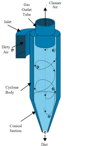
It is important to note that cyclones can vary drastically in their size. The size of the cyclone depends largely on how much flue gas must be filtered, thus larger operations tend to need larger cyclones. For example, several different models of one cyclone type can exist, and the sizes can range from a relatively small 1.2-1.5 meters tall (about 4-5 feet) to around 9 meters (30 feet)—which is about as tall as a three-story building.
Working:
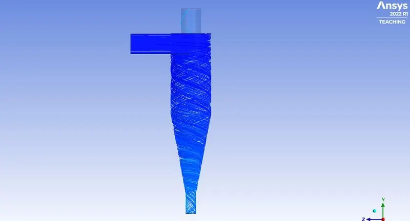
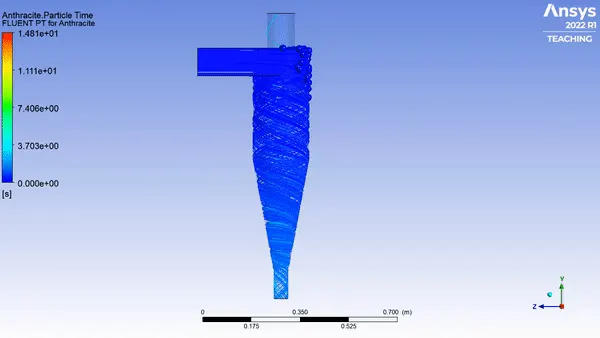
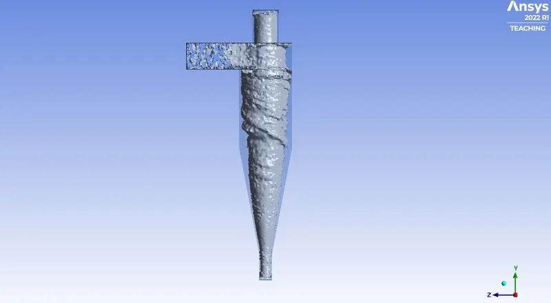
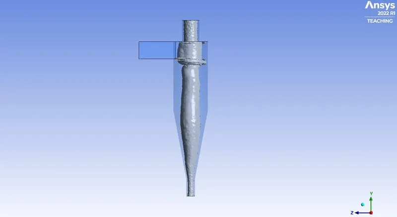
Cyclone separators work much like a centrifuge, but with a continuous feed of dirty air. In a cyclone separator, dirty flue gas is fed into a chamber. The inside of the chamber creates a spiral vortex, similar to a tornado. This spiral formation and the separation are shown in the Figure below. The lighter components of this gas have less inertia, so it is easier for them to be influenced by the vortex and travel up it. Contrarily, larger components of particulate matter have more inertia and are not as easily influenced by the vortex.
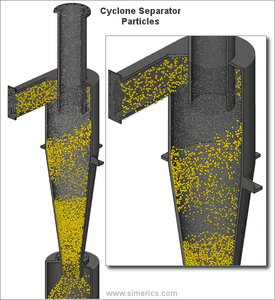
Most cyclones are built to control and remove particulate matter that is larger than 10 micrometers in diameter. However, there do exist high-efficiency cyclones that are designed to be effective on particles as small as 2.5 micrometers. As well, these separators are not effective on extremely large particulate matter. For particulates around 200 micrometers in size, gravity settling chambers or momentum separators are a better option.
Out of all of the particulate-control devices, cyclone separators are among the least expensive. They are often used as a pre-treatment before the flue gas enters more effective pollution control devices. Therefore, cyclone separators can be seen as "rough separators" before the flue gas reaches the fine filtration stages.
Effectiveness:
Cyclone separators are generally able to remove somewhere between 50-99% of all particulate matter in the flue gas. How well the cyclone separators are actually able to remove this matter depends largely on particle size. If there is a large amount of lighter particulate matter, fewer of these particles are able to be separated out. Because of this, cyclone separators work best on flue gases that contain large amounts of big particulate matter.
There are several advantages and disadvantages of using cyclone separators. First, cyclone separators are beneficial because they are not expensive to install or maintain, and they have no moving parts. This keeps maintenance and operating costs low. Second, the removed particulate matter is collected when dry, which makes it easier to dispose of. Finally, these units take up very little space. Although effective, there are also disadvantages in using cyclone separators. Mainly because the standard models are not able to collect particulate matter that is smaller than 10 micrometers effectively and the machines are unable to handle sticky or tacky materials well
Description of the project statement:
1. With varying the particle diameter, at a constant velocity at the inlet the flow is simulated. separation efficiency is found out.
2. With varying the velocity at the inlet, at a constant diameter of the particles, the flow is simulated. separation efficiency and pressure drop in the cases are found out.
SIMULATION PROCEDURE:
GEOMETRY:
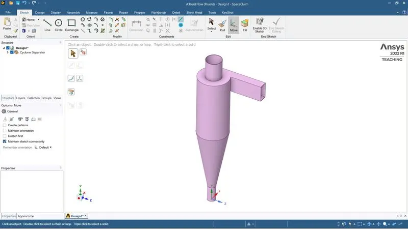
- First, the geometry is imported into the Ansys Spaceclaim.
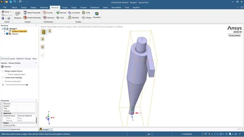
- Then the fluid volume is extracted from the model using the volume extraction tool available in SpaceClaim.
MESH:
- The named selection such as inlet and two outlets are assigned to the models using the named selection option available in the meshing module.
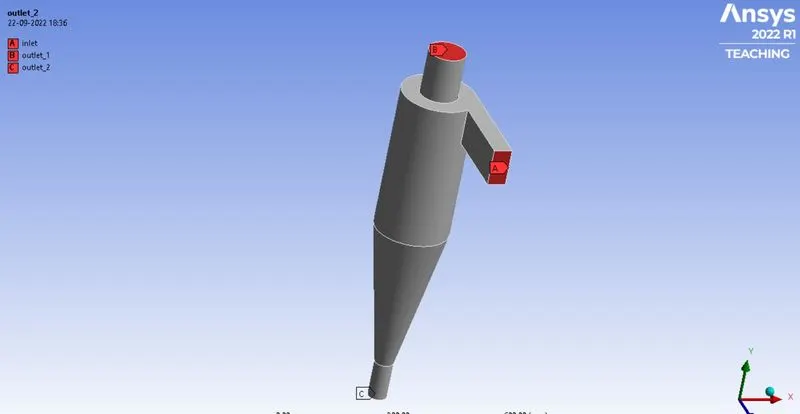
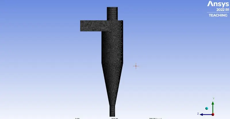
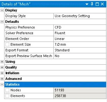
- The mesh is created for the model with a mesh size of 7mm.
SETUP:
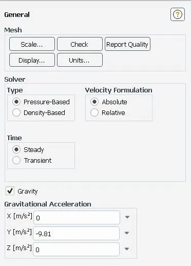
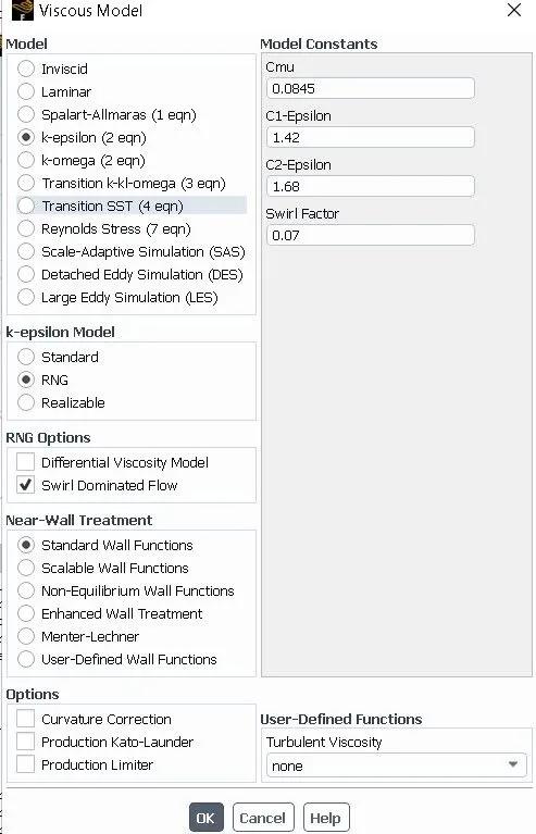
GENERAL:
- Time – steady state
- Solver type – pressure based
- Velocity formulation – absolute
- Gravity - -9.81 m/s2 [y- direction]
DISCRETE PHASE MODEL:
Discrete phase modeling is a method in which the flow of the discrete phase with a continuous flow is modeled. DPM is used to track individual particles through the continuum fluid. The lagrangian discrete phase model follows the lagrangian approach. The fluid phase is treated as a continuum by solving the Navier-stokes equation, while the dispersed phase is solved by tracking a large number of particles, bubbles, or droplets through the calculated flow field. The dispersed phase can exchange momentum, mass, and energy with the fluid phase.
In this case, solid particle size ranging from 1micrometer to 5micrometer is being simulated as a discrete phase.
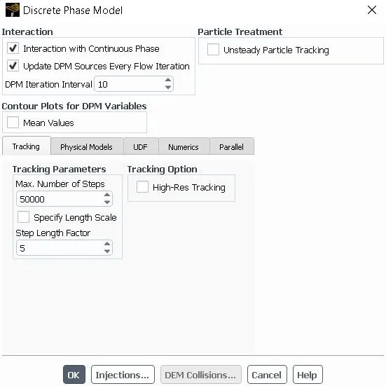
- Enabled interaction with continuous phase – to enable coupled flow
- Enabled update DPM sources every flow iteration.
- Tracking parameters – maximum no of steps – 50000.
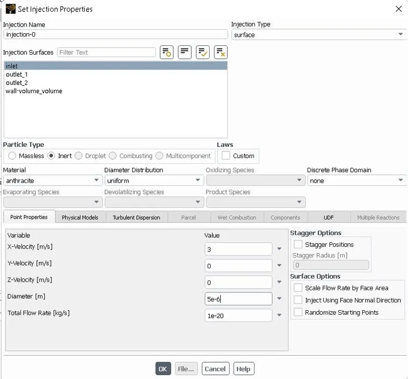
- Injection type - surface
- Particle type – inert
- Diameter distribution - uniform
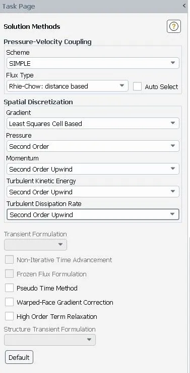
Solution Methods:
BOUNDARY CONDITION:
INLET:
- Velocity – Case 1: 1m/s
Case 2: 3m/s
Case 3: 5m/s
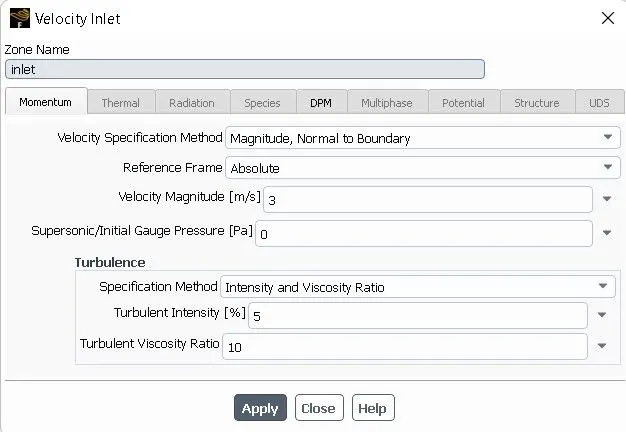
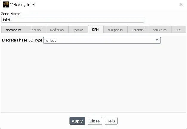
OUTLET1:
- Gauge pressure – zero pa
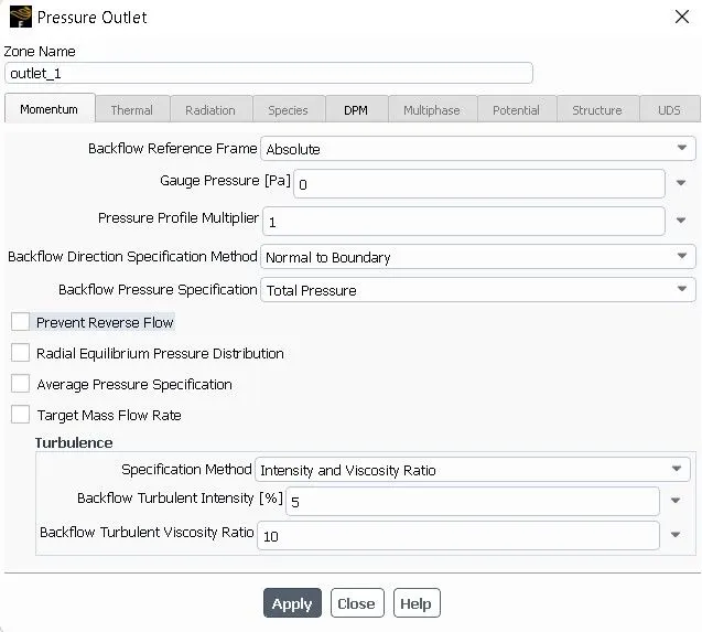
- DPM BC type –escape
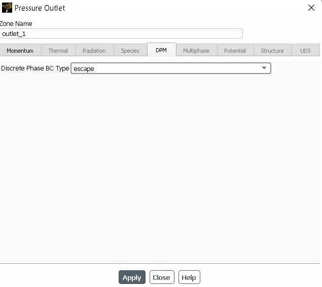
OUTLET2:
- Gauge pressure – zero pa
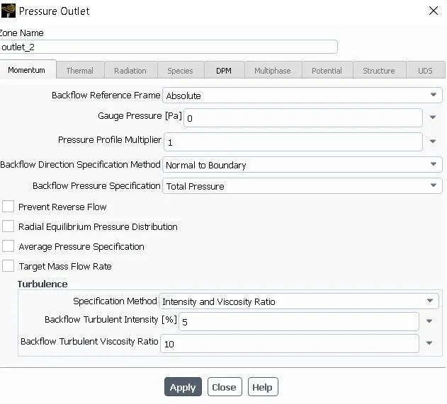
- DPM BC type–trap
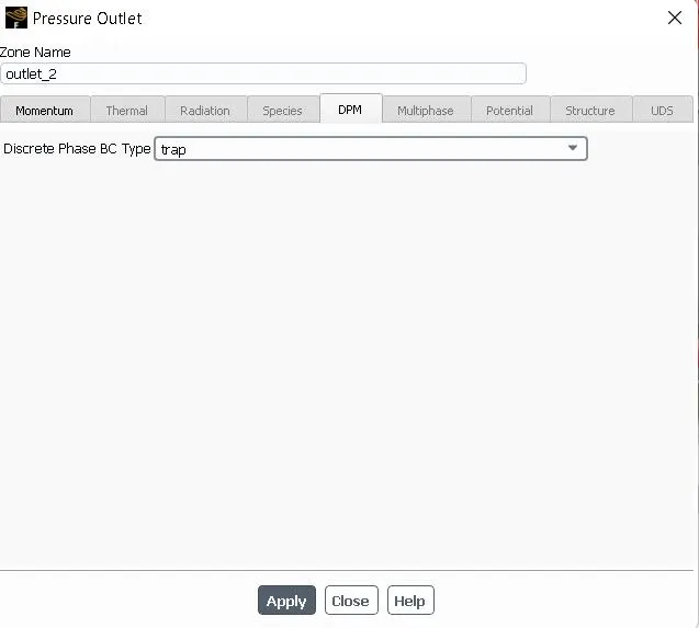
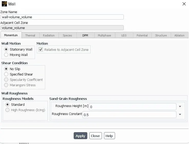
WALL BC:
- Wall motion – stationary
- Shear condition – no slip
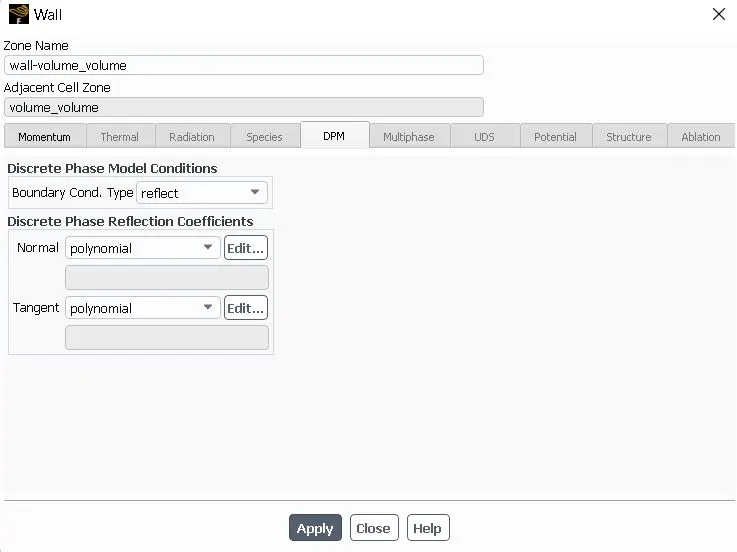
- Wall roughness - standard
- DPM BC type - reflect
INITIALIZATION:
Standard initialization
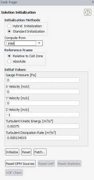

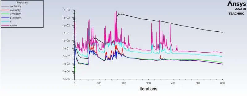
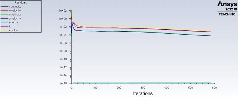
The simulation is run for 600 iterations.
RESULTS:
1. To perform an analysis on a given cyclone separator model by varying the particle velocity from 1 m/sec to 5 m/sec and calculate the separation efficiency and pressure drop in each case.
CASE1 – VELOCITY: 1M/S AND DIAMETER: 5 MICROMETER:
RESIDUAL:
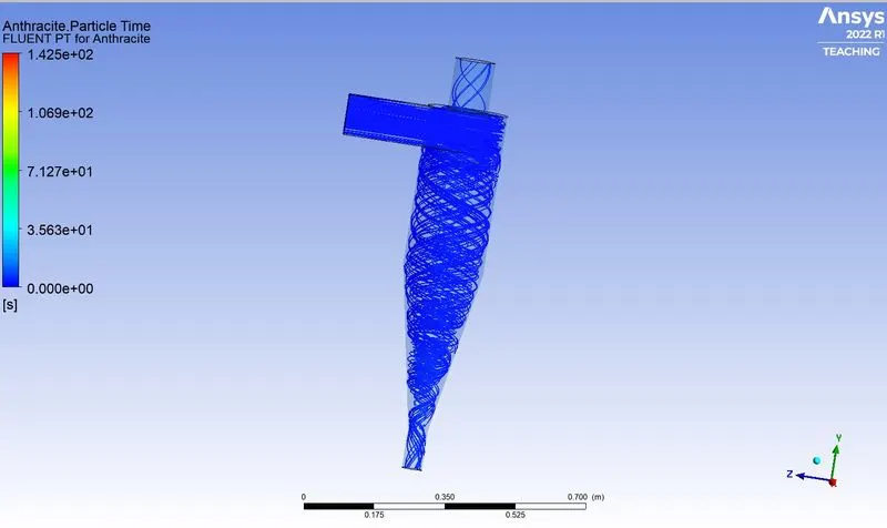
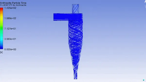
ANTHRACITE PARTICLE TIME:
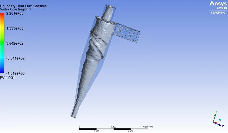
VORTEX CORE REGION:
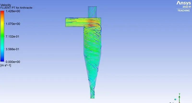
VELOCITY PLOT:
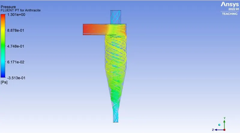
PRESSURE PLOT:
PARTICLE DATA:
Separation efficiency = No. of a particle trapped/No. of particle tracked
separation efficiency = (8/120)*100 = 6.67%
CASE2 – VELOCITY: 3M/S AND DIAMETER: 5 MICROMETER:
RESIDUAL:
ANTHRACITE PARTICLE TIME:
VORTEX CORE REGION:
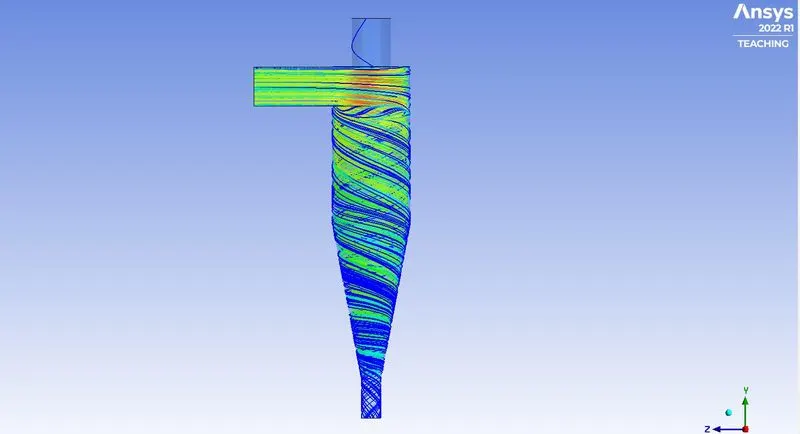
VELOCITY PLOT:
PRESSURE PLOT:
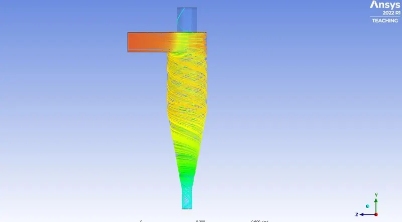
PARTICLE DATA:
Separation efficiency = No. of a particle trapped/No. of particle tracked
separation efficiency = (119/120)*100 = 99.17%
CASE3 – VELOCITY: 5M/S AND DIAMETER: 5 MICROMETER:
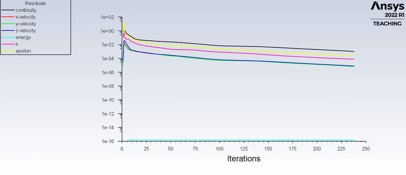
RESIDUAL:
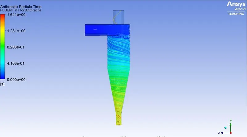
ANTHRACITE PARTICLE TIME:
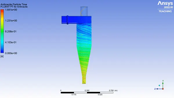
VORTEX CORE REGION:
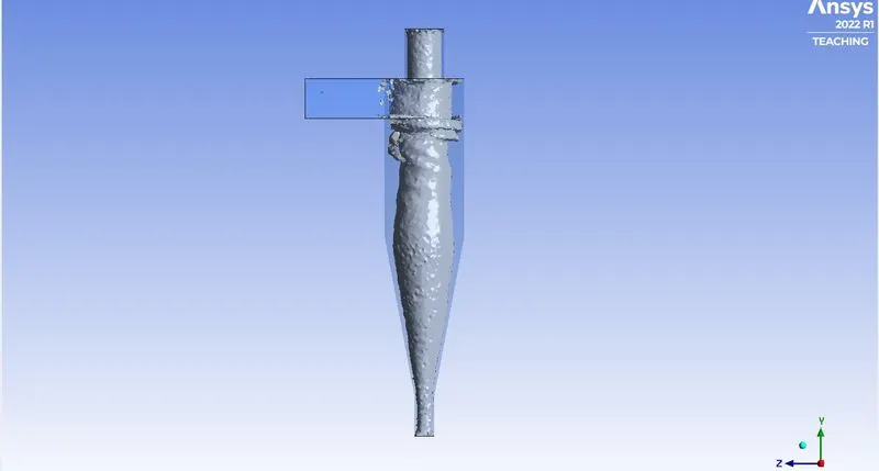
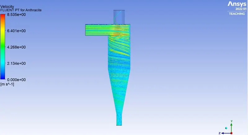
VELOCITY PLOT:
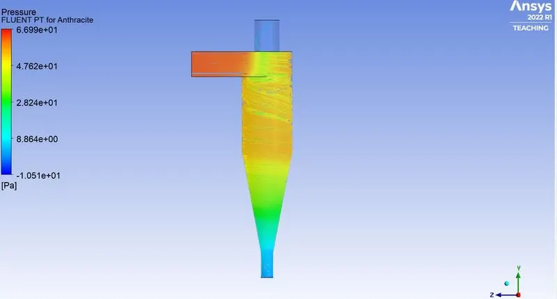
PRESSURE PLOT:
PARTICLE DATA:

Separation efficiency = No. of a particle trapped/No. of particle tracked
separation efficiency = (120/120)*100 = 100%
SUMMARY:
| CASES | VELOCITY (m/s) | DIAMETER (μm) | PRESSURE DROP(pa) | SEPARATION EFFICIENCY(%) |
| CASE 1 | 1m/s | 5μm | 0.516 pa | 6.67% |
| CASE 2 | 3m/s | 5μm | 5.325 pa | 99.17% |
| CASE 3 | 5m/s | 5μm | 15.35 pa | 100% |
2. To analyze a given cyclone separator model by varying the particle diameter from 1 μm to 5 μm and calculate the separation efficiency in each case.
CASE1 – VELOCITY: 3M/S AND DIAMETER : 1MICROMETER:
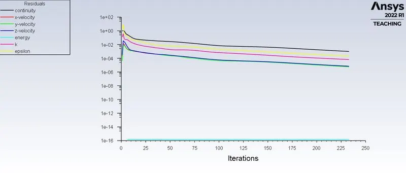
RESIDUAL:
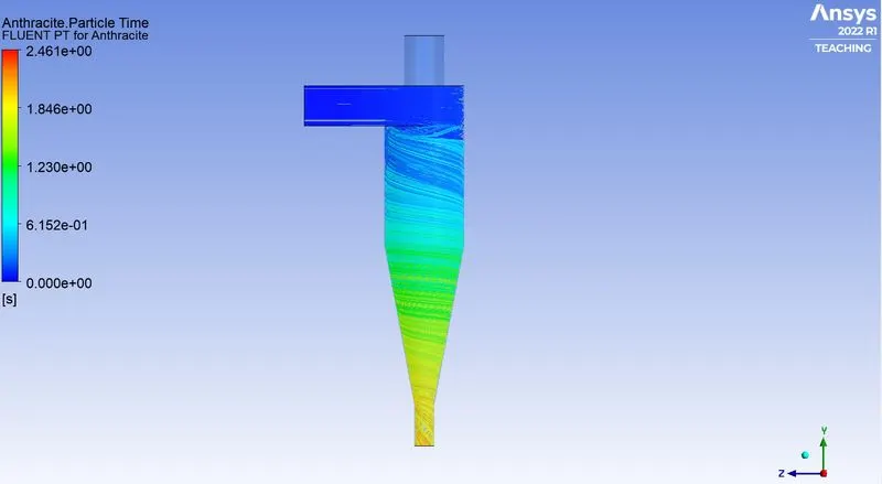
ANTHRACITE PARTICLE TIME:
VORTEX CORE REGION:
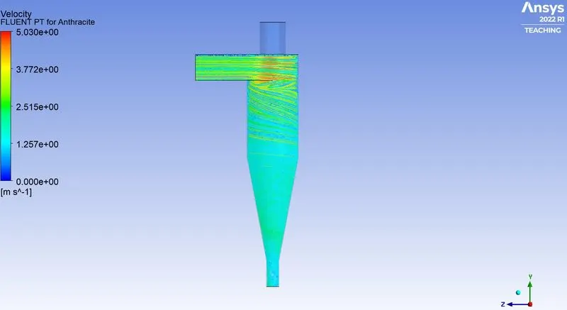
VELOCITY PLOT:
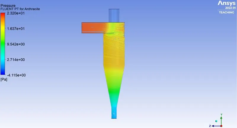
PRESSURE PLOT:
PARTICLE DATA:
Separation efficiency = No. of a particle trapped/No. of particle tracked
separation efficiency = (34/120)*100 = 28.33%
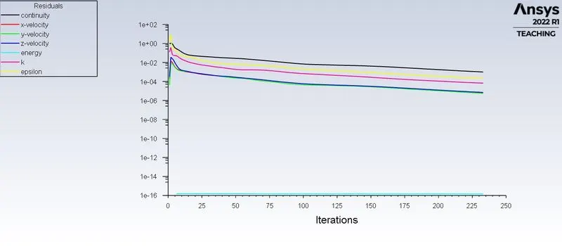
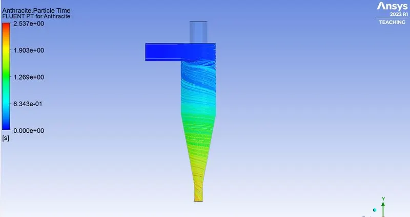
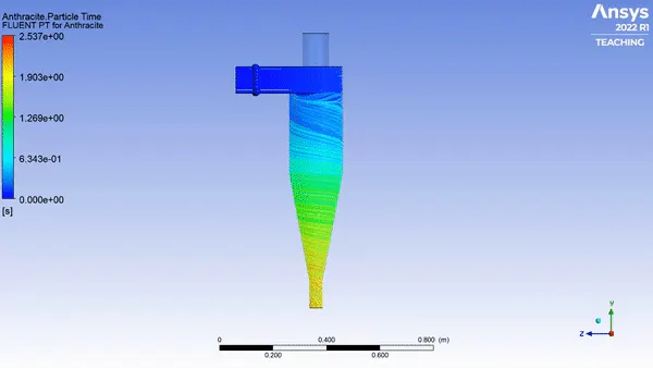
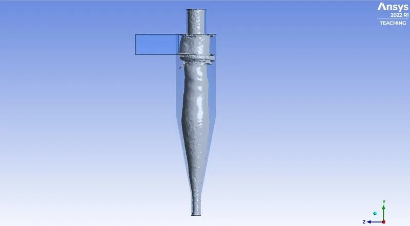
CASE2 – VELOCITY: 3M/S AND DIAMETER : 3MICROMETER:
RESIDUAL:
ANTHRACITE PARTICLE TIME:
VORTEX CORE REGION:
VELOCITY PLOT:
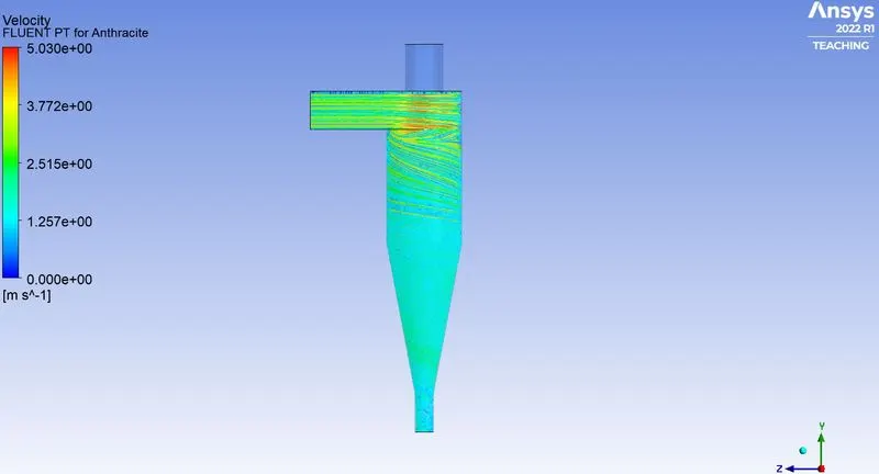
PRESSURE PLOT:
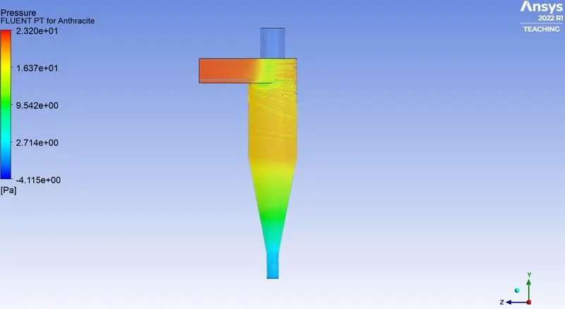
PARTICLE DATA:
Separation efficiency = No. of a particle trapped/No. of particle tracked
separation efficiency = (105/120)*100 = 87.5%
CASE3 – VELOCITY: 3M/S AND DIAMETER: 5 MICROMETER:
RESIDUAL:
ANTHRACITE PARTICLE TIME:
VORTEX CORE REGION:
VELOCITY PLOT:
PRESSURE PLOT:
PARTICLE DATA:
Separation efficiency = No. of a particle trapped/No. of particle tracked
separation efficiency = (119/120)*100 = 99.17%
SUMMARY:
| CASES | VELOCITY (m/s) | DIAMETER (μm) | PRESSURE DROP(pa) | SEPARATION EFFICIENCY(%) |
| CASE 1 | 3m/s | 1 μm | 5.325 pa | 28.33% |
| CASE 2 | 3m/s | 3 μm | 5.325 pa | 87.5% |
| CASE 3 | 3m/s | 5 μm | 5.325 pa | 99.17% |
CONCLUSION:
- Particle size is a large design consideration affecting a separator’s efficiency. Larger particles can be more easily separated than smaller particles. A reduction in particle size will give a corresponding reduction in efficiency.
- As the velocity increased, separation efficiency also increased.
- There is an increase in the pressure drop in the system with the increase in inlet velocity.