Week 7 - Simulation of a 1D Super-sonic nozzle flow simulation using Macormack Method
Simulation of a 1D Super-sonic nozzle flow simulation using Macormack Method
AIM:
To Simulate the isentropic flow through a Quasi 1D subsonic nozzle by deriving both the conservation and non-conservation forms of the governing equations and solve them by implementing the MacCormack's technique using MATLAB
Determine the steady-state temperature distribution for the flow-field variables and to investigate the difference between the two forms of governing equations by comparing their solutions along with the plots stated below.
1. Steady-state distribution of primitive variables inside the nozzle
2. Time-wise variation of the primitive variables
3. Variation of Mass flow rate distribution inside the nozzle at different time steps during the time-marching process
4. Comparison of Normalized mass flow rate distributions of both forms.
Theory:
A nozzle is a type of device designed to control the direction or characteristics of fluid flow at the exit of a pipe (or such system). A nozzle is often a pipe or tube of varying cross-sectional area, thus can be used to direct or modify flow of a fluid.
A convergent-divergent nozzle (also known as CD nozzle or de Laval nozzle) is a device used to accelerate a hot, pressurized gas passing through it to a higher supersonic speed in the axial direction by converting heat energy of the flow to kinetic energy. Hence, such nozzles are widely used in steam turbines, supersnic jet engines and rocket engine nozzles. Its operation relies on the different properties of gases flowing at subsonic, sonic and supersonic speeds.
In the field of CFD, MacCormack method is a prominent discretization scheme for obtaining numerical solutions of hyperbolic partial differential equations. (based on second-order finite difference method). It is the variation of two-step Lax-Wendroff scheme but much simple in application.
In this project, the problem is taken from JD Anderson's book on CFD.
SCHEMATIC FOR SUBSONIC- SUPERSONIC NOZZLE FLOW :
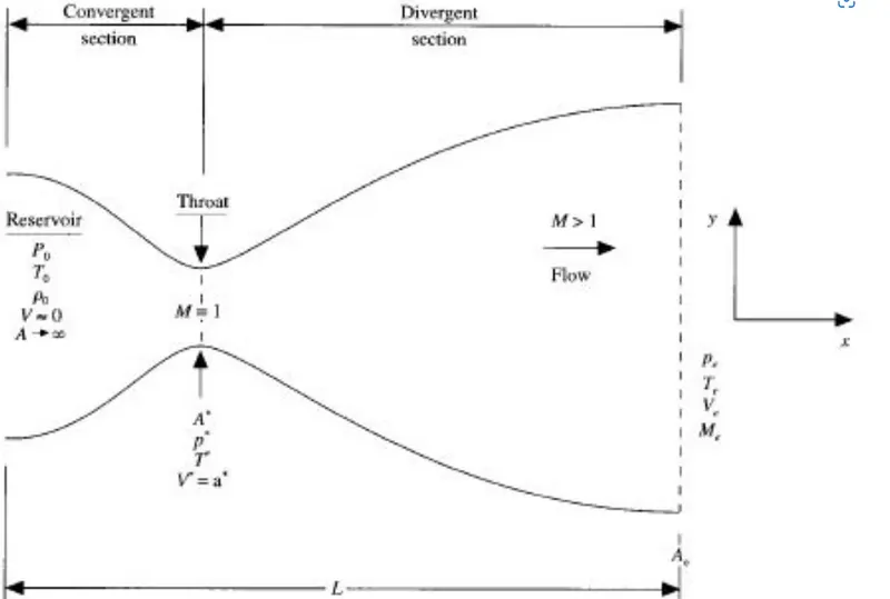
The above figure shows a schematic diagram of a convergent-divergent nozzle.
The flow and inlet of the nozzle come from the reservoir. For the convergent section, flow is subsonic MACH NUMBER <1, divergent section flow is supersonic MACH NUMBER>1 and at throat flow is sonic
MACH NUMBER =1.
`M = v /(√ T)`
where:
M is the Mach number
v is the velocity of the flow
T is the speed of sound
GOVERNING EQUATIONS :
As we consider the flow-through is only a function of X and not Y, hence we must apply an integral form of the Navier-stokes equation to a control volume consistent with the quasi-1D assumption.Hence by referring to the below figure we obtain the PDE form of governing equations from integral forms.
The shaded region below the figure shows the control volume, and slice of nozzle flow with the infinitesimal thickness of dx.
Maccormack method:
To discretize the numerical solution we use the technique called the Macormack method. The MacCormack method is a variation of the two-step Lax-Wendroff Scheme but is much simpler in the application.
The application of the Maccormack method proceeds in two steps; a predictor step which is followed by a corrector step.
Predictor step:
the predictor step, a "provisional" value of "u" at time level n+1 (denoted by `u_i^(overline(n+1))`)is estimated obtained by replacing the spatial and temporal derivatives in the previous first-order equation using Forward Difference Scheme. `Deltat` is used for Timestep
Corrector step:
the corrector step, the predicted value `u_i^(overline(n+1)`is corrected according to the equation. Note that the corrector step uses the Backward Difference Scheme for spatial derivative. The time step used in the corrector step is `(Deltat)/2`in contrast to the `Deltat`used in the predictor step.
NON CONSERVATIVE FORM :
Consider an infinitesimally small fluid element inside the nozzle, the fluid same fluid element moving along streamline, such type of condition is non-conservative form and the equation obtained in such cases are called as a non-conservative form of governing equation.



Predictor method.
we will be applying the forward differencing to the right-hand side spatial derivatives in the predictor method.
The continuity equation for the non-conservative form for the predictor method.

The momentum equation for the non-conservative form for the predictor method.

The energy equation for the non-conservative form for the predictor method

From these we get the predicted equation as follows: These are denoted by barred quantities.
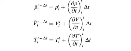
In these equations `ρ_i^t,``V_i^(t)and T_i^t`are the known values at time t.
Corrector method.
In the corrector method rearward differencing is applied to the right-hand side spatial derivatives.
The continuity equation for the non-conservative form for the corrector method.
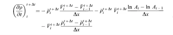
The Momentum equation for the non-conservative form for the corrector method.

The energy equation for the non-conservative form for the corrector method.
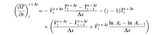
The average time derivatives.
by adding both the conservative and non-conservative equations and taking the average of them we get, density, velocity, and temperature terms as,
It's basically half of the sum of the corrector and predictor value.
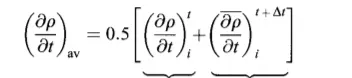
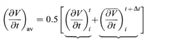

Then finally the corrected values at time `t+Deltat` are:
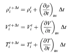
Calculation of time step:
`d t = C ⋅ (d x)/( u + a)`
where C is the courant number its value is 0.5
u is the local velocity
a is the local speed of sound
Boundry conditions at subsonic section
By using linear extrapolation
`V _1 = 2 ⋅ V _2 − V _3`
Density and Temperature at point 1 is held fixed.

Supersonic outflow boundry conditions:
`V _N = 2 ⋅ V_(N − 1) − V_(N − 2)`
`ρ _N = 2 ⋅ ρ_(N − 1) − ρ_(N − 2)`
`T _N = 2 ⋅T_ (N − 1) − T_(N − 2)`
CONSERVATIVE FORM :
Consider an infinitesimally small fluid element inside the nozzle, and the fluid moving through that element, such type of condition is conservative form, and the equation obtained in such cases are called as called a conservative form of governing equations.



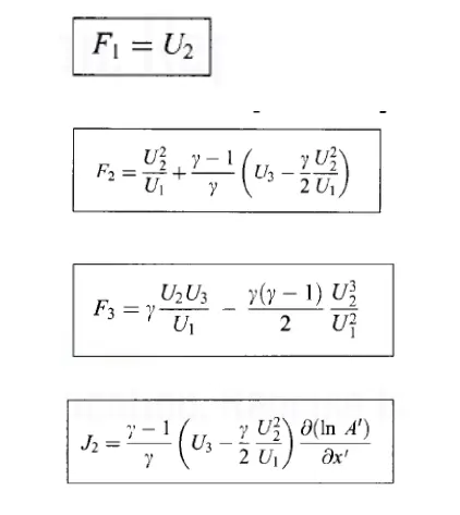
The above is the non-dimensional conservation form of the continuity, momentum and energy equations for quasi-one-dimensional flow, respectively.The equations for quasi-one-dimensional flow can be expressed in generic form.Let us define the elements of the solution vector U, flux vector F, and the source term J as follows
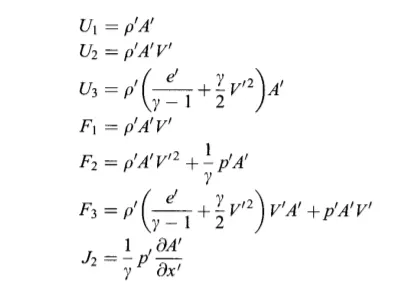
From the above equations we can write that
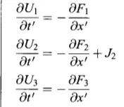
These are the equations we wish to solve numerically by using the MacCormacks technique.
To obtain the primitve variables we must decode the elements U1,U2,U3 as follows.From the defination of U1,U2 and U3 given above we have
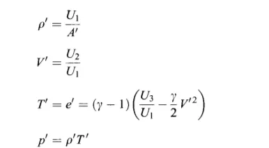
Expressing the flux and source term in form of solution vectors
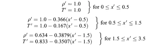
Initial conditions:
Applying the boundry conditions:
Inlet boundry conditions:
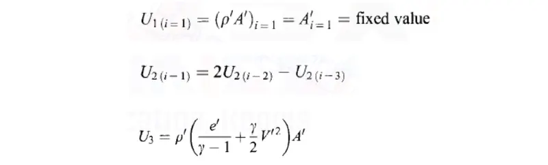
Outlet boundry condition:The flow properties at the downstream ,supersonic outflow boundry are obtained by linear extrapolation from the two adjacent internal points.
If N denotes the grid point at the outflow boundry ,then:
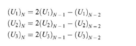
The values of F1,F2 and F3 at grid point i=N are obtained from the values of U1,U2 and U3 at point i=N using the equations.
Let's start with the clear commands clear all, close all, clc
And then assigning the values that are for n, x, dx, gamma as input parameters.
calculating the initial profile for both the conservative and non-conservative forms that is density, temperature, and velocity values, and also calculating the area and assigning the number of time steps.
and we have created the functions to compute for both the conservative and non-conservative forms plottings will also be done within the functions so in the main program, we are just going to call those functions to get the results.
and only one plot has to be made in the main program which is to compare both the conservative and non-conservative mass flow rates in a single graph that can be done.
Matlab Codes:
Function code:
Non-Conservative :
function [mfr_nc,mfr_throat_nc]=non_conservative(L,n,nt,cfl)


x=linspace(0,L,n);
dx=x(2)-x(1);

% initial conditions rho, a, v, T, mfr, M, p
rho = 1-0.3146*x;
T= 1-0.2314*x;
v=(0.1+1.09*x).*T.^0.5;
a= 1+2.2*(x-1.5).^2;
M= v./(T.^0.5);
mfr = rho.*a.*v;
p=rho.*T;

g = 1.4;

for z=1:31
    u=(T(z))^(1/2);
    dt(z) = cfl*dx/(u + v(z));
end
dt=min(dt);

for i = 1:length(nt)
  %storing initial values
    rho_old = rho;
    T_old = T;
    v_old = v;
  for j=2:n-1
  %predictor step
    drho_dx = (rho(j+1)-rho(j))/dx;
    dv_dx = (v(j+1)-v(j))/dx;
    dT_dx = (T(j+1)-T(j))/dx;
    da_dx = (log(a(j+1))-log(a(j)))/dx;
    drho_dt_p(j) = -rho(j)*dv_dx - rho(j)*v(j)*da_dx - v(j)*drho_dx;        %continuty
    dv_dt_p(j) = -v(j)*dv_dx - (1/g)*(dT_dx + (T(j)/rho(j))*drho_dx);       %momentum
    dT_dt_p(j) = -v(j)*dT_dx - (g-1)*T(j)*(dv_dx + v(j)*da_dx);             %energy
  %updating primitives
    v(j) = v_old(j) + dv_dt_p(j)*dt;
    rho(j) = rho_old(j) + drho_dt_p(j)*dt;
    T(j) = T_old(j) + dT_dt_p(j)*dt;
  %corrector step
    drho_dx = (rho(j)-rho(j-1))/dx;
    dv_dx = (v(j)-v(j-1))/dx;
    dT_dx = (T(j)-T(j-1))/dx;
    da_dx = (log(a(j))-log(a(j-1)))/dx;
    drho_dt_c(j) = -rho(j)*dv_dx - rho(j)*v(j)*da_dx - v(j)*drho_dx;        %continuity
    dv_dt_c(j) = -v(j)*dv_dx - (1/g)*(dT_dx + (T(j)/rho(j))*drho_dx);       %momentum
    dT_dt_c(j) = -v(j)*dT_dx - (g-1)*T(j)*(dv_dx + v(j)*da_dx);             %energy
  end
  %average time derivatives
    drho_dt_avg = 0.5*(drho_dt_p + drho_dt_c);
    dv_dt_avg = 0.5*(dv_dt_p + dv_dt_c);
    dT_dt_avg = 0.5*(dT_dt_p + dT_dt_c);
  %final corected values
  for k = 2:n-1
    rho(k) = rho_old(k) + drho_dt_avg(k)*dt;
    v(k) = v_old(k) + dv_dt_avg(k)*dt;
    T(k) = T_old(k) + dT_dt_avg(k)*dt;
  end
  %entry boundary conditions
    v(1) = 2*v(2)-v(3);
  %exit boundary conditions
    v(n) = 2*v(n-1)-v(n-2);
    rho(n) = 2*rho(n-1)-rho(n-2);
    T(n) = 2*T(n-1)-T(n-2);
  %Final update of primitives
    p = rho.*T;
    M= v./T.^0.5;
    error(k) =  abs(v(k)-v(k-1));
    mfr= rho.*a.*v;
  %to find values at throat point
    T_throat(i) = T(16);
    rho_throat(i) = rho(16);
    v_throat(i) = v(16);
    M_throat(i) = M(16);
    p_throat(i) = p(16);
    error_throat(i)=error(16);
    mfr_throat(i)=mfr(16);
    if n==31
for ii=[1:50:201 700]
    if ii==i
       figure(1)
     plot(x,mfr,'linewidth',1)
     hold on
     title ('Non-Conservative - Variation of Mass flow rate distribution inside the nozzle at different time steps during the time-marching process')
     xlabel('Length of nozzle')
     ylabel('Mass flow rate')
    elseif i==1400
     plot(x,mfr,'*r')
     legend('at 1','at 51','at 101','at 151','at 201','at 700','at 1400')
    end
end
end

end
if n==31
figure(2)
     plot(x,v,'b',x,p,'r',x,T,'k',x,rho,'m',x,M,'g',x,mfr,'c')
     ylim([-0.1 3.7])
     title (sprintf('Time step = %d',i))
     xlabel('Length of nozzle')
     ylabel('Non dimensional parameters')
     legend('Velocity','Pressure','Temperature','Density','Mach number','Mass flow rate','location','northwest')
     title('Non-Conservative - Steady-state distribution of primitive variables inside the nozzle')

figure (3)
plot(nt,rho_throat)
hold on
plot(nt,v_throat,'linewidth',1)
plot(nt,p_throat,'linewidth',1)
plot(nt,T_throat,'linewidth',1)
plot(nt,M_throat,'linewidth',1)
plot(nt,mfr_throat,'linewidth',1)
xlabel('Time steps (nt)')
ylabel('Non dimensional parameters')
legend('Density','Velocity','Pressure','Temperature','Mach number','Mass flow rate')
title('Non-Conservative - Time-wise variation of the primitive variables at throat point i=16')
end
mfr_nc=mfr;
mfr_throat_nc=mfr_throat;
end
Conservative :
function [mfr_c,mfr_throat_c]=conservative(L,n,nt,cfl)

x=linspace(0,L,n);
dx=x(2)-x(1);

% initial conditions rho, a, v, T, M, mfr, p
for ii=1:length(x)
    if (x(ii)<=0.5)
        rho(ii) = 1;
        T(ii) = 1;
    elseif (x(ii)>0.5) & (x(ii)<=1.5)
        rho(ii) = 1-0.366*(x(ii)-0.5);
        T(ii)= 1-0.167*(x(ii)-0.5);
    elseif (x(ii)>1.5) & (x(ii)<=3.5)
        rho(ii) = 0.634-0.3879*(x(ii)-1.5);
        T(ii)= 0.833-0.3507*(x(ii)-1.5);
    end
end
a= 1+2.2*(x-1.5).^2;     %area
g = 1.4;                 %gamma value
% solution vectors u1, u2, u3
u1 = rho.*a;
u2 = 0.59*ones(1,n);
v=u2./u1;
u3 = u1.*((T./(g-1))+(g/2).*v.^2);

M= v./(T.^0.5);          %mach number
mfr = rho.*a.*v;         %mass flow rate
p=rho.*T;                %pressure


for z=1:31               %to find dt value
u=(T(z))^(1/2);
dt(z) = cfl*dx/(u + v(z));
end
dt=min(dt);

for i = 1:length(nt)
    %storing initial values
    u1_old = u1;
    u2_old = u2;
    u3_old = u3;

    for j=2:n-1
   %flux vectors
        f1 = u2;
        f2 = ((u2.^2)./u1)+((g-1)/g)*(u3-((g/2)*(u2.^2)./u1));
        f3 = ((g.*u2.*u3)./u1) - ((g*(g-1)/2)*(u2.^3)./(u1.^2));
   %source term
        j1 = (1/g)*rho(j)*T(j)*((a(j+1)-a(j))/dx);
   %predictor step
        du1_dt_p(j)= -(f1(j+1)-f1(j))/dx;           %continuity
        du2_dt_p(j)= -(f2(j+1)-f2(j))/dx + j1;      %momentum
        du3_dt_p(j)= -(f3(j+1)-f3(j))/dx;           %energy
   %updating solution vectors
        u1(j) = u1_old(j) + du1_dt_p(j)*dt;
        u2(j) = u2_old(j) + du2_dt_p(j)*dt;
        u3(j) = u3_old(j) + du3_dt_p(j)*dt;
   %updating primitives
        rho=u1./a;
        T=(g-1).*(u3./u1-(g/2).*(u2./u1).^2);
   %updating flux terms
        f1=u2;
        f2=u2.^2./u1+((g-1)/g).*(u3-(g/2)*u2.^2./u1);
        f3=g.*u2.*u3./u1-0.5*g*(g-1).*u2.^3./u1.^2;
   %source term for corrector step
        j2 = (1/g)*(rho(j)*T(j)*(a(j)-a(j-1))/dx);
   %corrector step
        du1_dt_c(j) = -(f1(j)-f1(j-1))/dx;            %continuity
        du2_dt_c(j) = -(f2(j)-f2(j-1))/dx + j2;       %momentum
        du3_dt_c(j) = -(f3(j)-f3(j-1))/dx;            %energy
    end
    %average time derivatives
        du1_dt_avg = 0.5*(du1_dt_p + du1_dt_c);
        du2_dt_avg = 0.5*(du2_dt_p + du2_dt_c);
        du3_dt_avg = 0.5*(du3_dt_p + du3_dt_c);
    %final corected values
    for k = 2:n-1
        u1(k) = u1_old(k) + du1_dt_avg(k)*dt;
        u2(k) = u2_old(k) + du2_dt_avg(k)*dt;
        u3(k) = u3_old(k) + du3_dt_avg(k)*dt;
    end
    %entry boundary conditions
        u1(1) = a(1);
        u2(1) = 2*u2(2)-u2(3);
        u3(1) = u1(1)*(T(1)/(g-1) + (g*(u2(1)/u1(1))^2)/2);
    %exit boundary conditions
        u1(n) = 2*u1(n-1)-u1(n-2);
        u2(n) = 2*u2(n-1)-u2(n-2);
        u3(n) = 2*u3(n-1)-u3(n-2);

    %Final update of primitives
        rho = u1./a;
        v = u2./u1;
        T=(g-1).*(u3./u1-(g/2).*(u2./u1).^2);
        p = rho.*T;
        M= v./T.^0.5;
        error(k) =  abs(v(k)-v(k-1));
        mfr= u2;
  %to find values at throat point
    T_throat(i) = T(16);
    rho_throat(i) = rho(16);
    v_throat(i) = v(16);
    M_throat(i) = M(16);
    p_throat(i) = p(16);
    error_throat(i)=error(16);
    mfr_throat(i)=mfr(16);

if n==31
    for ii=[1:50:201 700]
    if ii==i
       figure(4)
     plot(x,mfr,'linewidth',1)
     hold on
     title ('Conservative - Variation of Mass flow rate distribution inside the nozzle at different time steps during the time-marching process')
     xlabel('Length of nozzle')
     ylabel('Mass flow rate')
    elseif i==1400
     plot(x,mfr,'*r')
     legend('at 1','at 51','at 101','at 151','at 201','at 700','at 1400')
    end
end
end

end
if n==31
figure(5)
     plot(x,v,'b',x,p,'r',x,T,'k',x,rho,'m',x,M,'g',x,mfr,'c')
     ylim([-0.1 3.7])
     title (sprintf('Time step = %d',i))
     xlabel('Length of nozzle')
     ylabel('Non dimensional parameters')
     legend('Velocity','Pressure','Temperature','Density','Mach number','Mass flow rate','location','northwest')
     title('Conservative - Steady-state distribution of primitive variables inside the nozzle')

figure (6)
plot(nt,rho_throat)
hold on
plot(nt,v_throat,'linewidth',1)
plot(nt,p_throat,'linewidth',1)
plot(nt,T_throat,'linewidth',1)
plot(nt,M_throat,'linewidth',1)
plot(nt,mfr_throat,'linewidth',1)
xlabel('Time steps (nt)')
ylabel('Non dimensional parameters')
legend('Density','Velocity','Pressure','Temperature','Mach number','Mass flow rate')
title('Conservative - Time-wise variation of the primitive variables at throat point i=16')
end
mfr_c=mfr;
mfr_throat_c=mfr_throat;

end
Main code:
%Simulation of a 1D Super-sonic nozzle flow simulation using the Macormack Method
close all
clear all
clc

L=3;                    %length of the nozzle
n=[31 62 93];           %number of grid points
nt=1:1400;              %number of time steps
cfl = 0.5;              %CFL number
for i = 1:length(n)
x=linspace(0,L,n(i));
[mfr_nc,mfr_throat_nc]=non_conservative(L,n(i),nt,cfl);
[mfr_c,mfr_throat_c]=conservative(L,n(i),nt,cfl);
figure(7)
subplot(2,1,1)
plot(nt,mfr_throat_c,'r',nt,mfr_throat_nc,'b','linewidth',1)
xlabel('Time steps (nt)')
ylabel('Mass flow rate')
legend('Conservative form','Non-Conservative form')
title('Mass flow rate using "Non-Conservative vs Conservative" at throat point i=16')

subplot (2,1,2)
plot(x,mfr_c,'g',x,mfr_nc,'y','linewidth',1)
xlabel('Length of nozzle')
ylabel('Mass flow rate')
legend('Conservative ','Non-Conservative ')
title('Mass flow rate using "Non-Conservative  vs Conservative " in the nozzle')

figure(8)
subplot (2,1,1)
plot(nt,mfr_throat_c,'linewidth',1)
hold on
xlabel('Time steps (nt)')
ylabel('Mass flow rate')
legend('at 31 nodes','at 62 nodes','at 93 nodes')
title('Conservative : Grid independency test at throat point i=16')
subplot (2,1,2)
plot(nt,mfr_throat_nc,'linewidth',1)
hold on
xlabel('Time steps (nt)')
ylabel('Mass flow rate')
legend('at 31 nodes','at 62 nodes','at 93 nodes')
title('Non-Conservative : Grid independency test at throat point i=16')
figure(9)
subplot (2,1,1)
plot(x,mfr_c,'linewidth',1)
hold on
xlabel('Length of nozzle')
ylabel('Mass flow rate')
legend('at 31 nodes','at 62 nodes','at 93 nodes')
title('Conservative: Grid independency test along the nozzle')
subplot (2,1,2)
plot(x,mfr_nc,'linewidth',1)
hold on
xlabel('Length of nozzle')
ylabel('Mass flow rate')
legend('at 31 nodes','at 62 nodes','at 93 nodes')
title('Non-Conservative: Grid independency test along the nozzle')

end
Outputs:
Graph
Non-Conservative :
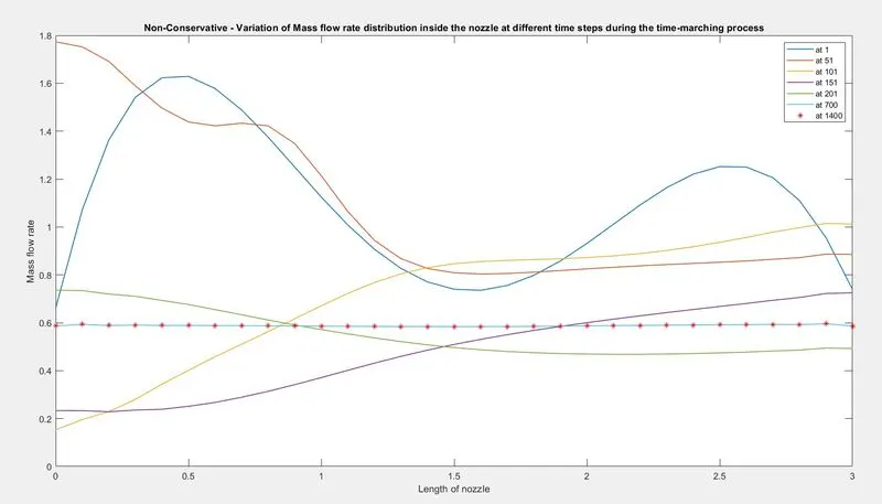
the above fig shows the variation of mass flow rate distribution inside the nozzle at different time steps during the time marching process. The mass flow rate finally settled at 0.58.
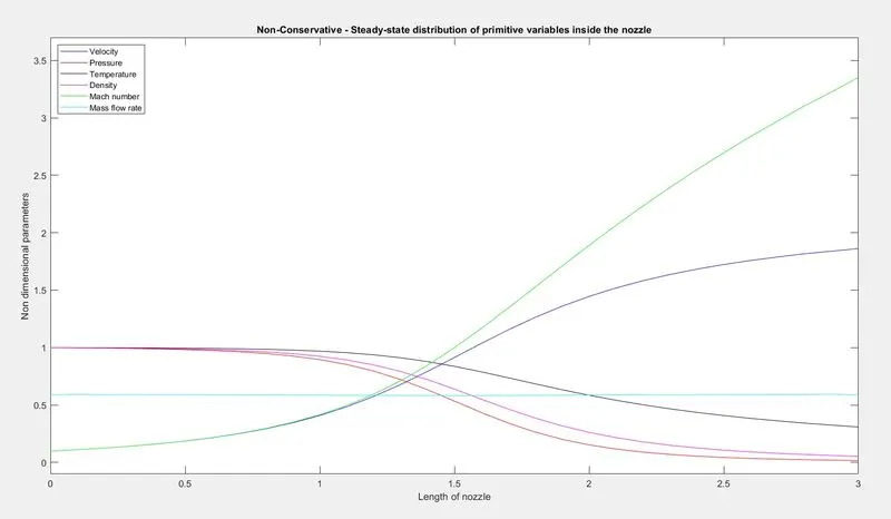
the above fig shows the Steady state distribution of non-dimensional primitive variables at the end of the time step. These values of flow field variables oblige the exact values shown in John D. Anderson's book.
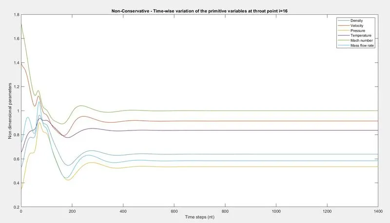
the above fig shows Time wise variation of primitive variables at throat point i =16. Around the time step of 500 the flow field variables obtained stable solution.
conservative :
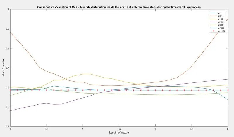
the above fig shows the variation of mass flow rate distribution inside the nozzle at different time steps during the time marching process. The mass flow rate finally settled at 0.56.
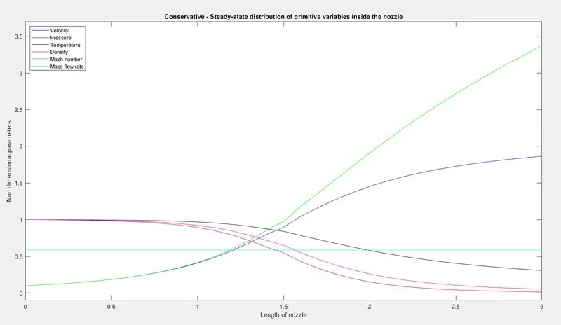
the above fig shows Steady state distribution of non-dimensional primitive variables at the end of the time step. These values of flow field variables oblige the exact values shown in John D. Anderson's book.
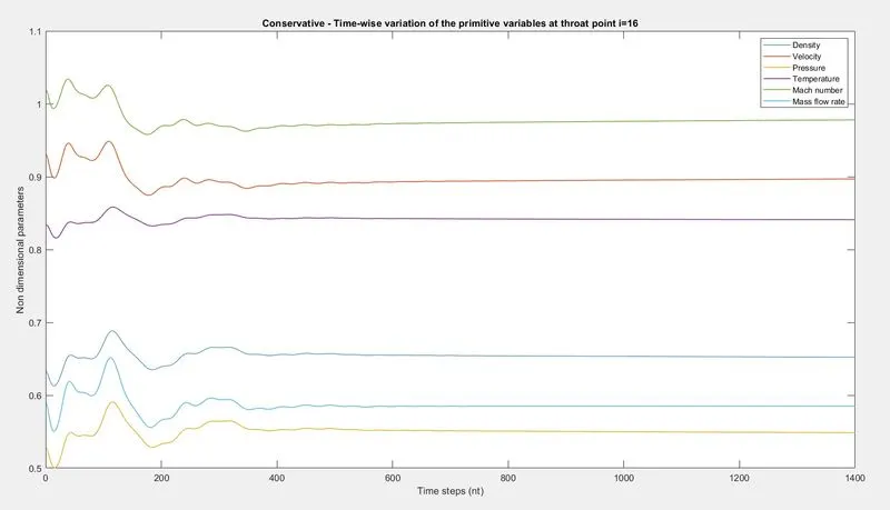
the above fig shows Time wise variation of primitive variables at throat point i =16. Around the time step of 600, the flow field variables obtained a stable solution.
Non-conservative form vs conservative form:

the above fig shows a comparison of mass flow rate using both conservative and non-conservative forms.
- from subplot 1: Both the forms reached the stable and exact solution by the end of the time steps. But the conservative form obtained stability at lesser time steps.
- from subplot 2: The difference between both the forms is very less in the nozzle. But the mass flow rate in the conservative form is constant whereas in the non-conservative form it is varying with 0.582±0.003.
- From fig, we can conclude that the final solution is not much change when using conservative and non-conservative forms. Although there is a slight change in the throat area alone in the conservative form, which is not considered significant. Though the stability is obtained at lesser time steps the computational time is more in the case of the conservative form than the other.
Grid independency test for both Non-conservative form & Conservative form:
plot(1)
plot(2)
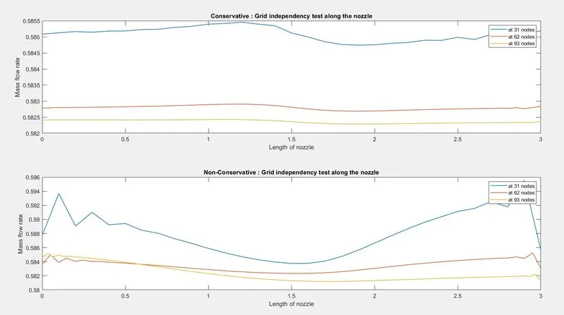
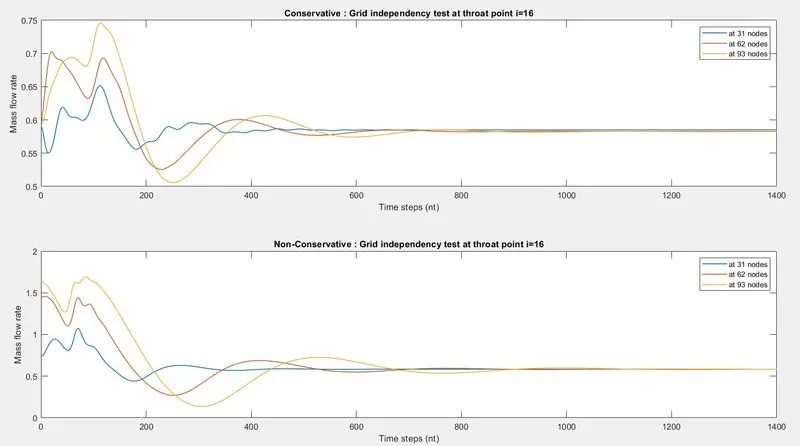
plot(1) and plot(2) show the grid independence test in both forms.
plot(1) - mass flow rate varying with time step at throat point - subplot(1) - conservative & subplot(2) - non-conservative .
At 3 different grid sizes, though the values are different at the start of the time marching process the solution obtained is stable and almost the same by the end of time marching.
plot(2) - mass flow rate in the nozzle - subplot(1) - conservative & subplot(2) - non-conservative.
The solution was obtained using 3 different grid sizes resulting in 3 different solutions within the range of 0.589±0.006. i.e. the difference between them is very small which can be neglected/ignored.
From plot(1) and plot(2), we can conclude that the plot is not much change when the number of grid points is doubled up and nearly tripled. Although there is a slight change at the throat area alone in the conservative form, which is not considered significant.
CONCLUSION.
Cumulating all the above results we can evidently conclude that the Conservative form converges slightly faster than the Non-Conservative form offering a stable solution along the simulation. Yet both forms are dependable in calculating the solutions which are almost precise.