Week_8_Plastic Model_1
B-PILLAR
The B-Pillar Is The Central Pillar Of The Car. This Pillar Is Actually a Sheet Metal Part Which Is Welded In The Biw Of The Car. The B-Pillar Trim Is Attached To The B-Pillar And Improves The Aesthetic Look Of The Car. Mostly The Trims Are Manufactured By The Injection Molding Process. The Design Of The B-Pillar Is Carefully Done To Make The Part Manufacturable And Usable In The Interior. While Manufacturing a Part Through Injection Molding a Lot Of Defects Can Occur On The Plastic Part Which Will Destroy The Look Of The Panel. The Design Has To Made In Such a Way That All The Errors Can Be Rectified.
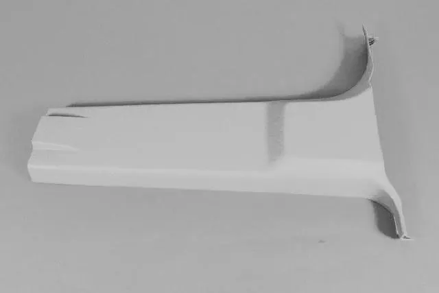
Objective: To model the given geometry of a B Pillar using 2d shell elements in Hypermesh.
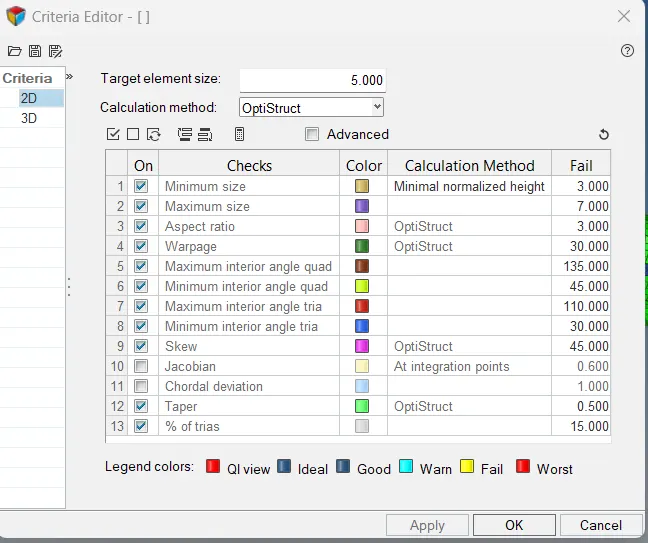
Element quality criteria :
|
S.N |
Quality Criteria |
Value |
|
1 |
Target Element Length |
5 mm |
|
2 |
Aspect Ratio |
3 |
|
3 |
Skewness |
45 |
|
4 |
Warping |
30 |
|
5 |
Taper |
0.5 |
|
6 |
Min. Length |
3 mm |
|
7 |
Max. Length |
7 mm |
|
8 |
Min angle Quad |
45 |
|
9 |
Max angle Quad |
135 |
|
10 |
Min angle Tria |
30 |
|
11 |
Max angle Tria |
110 |
|
12 |
Tria % |
15 |
Procedure:
- Import the given geometry of the B-Pillar in Hypermesh.
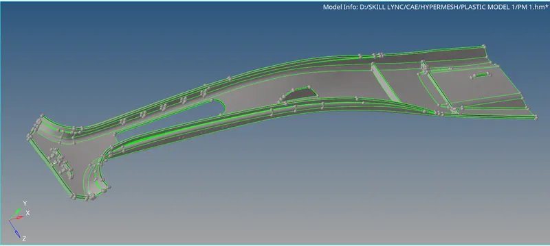
- Delete the solids in the geometry. Check for topological errors such as missing or distorted faces. The imported geometry was clean and thus where was no need for topology clean-up.
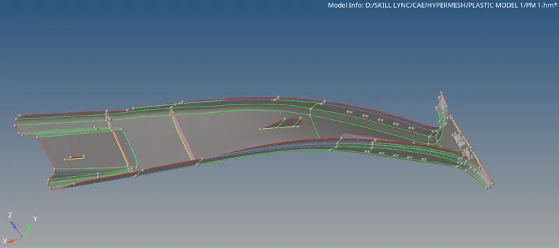
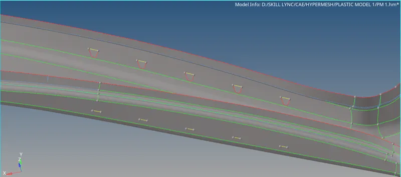
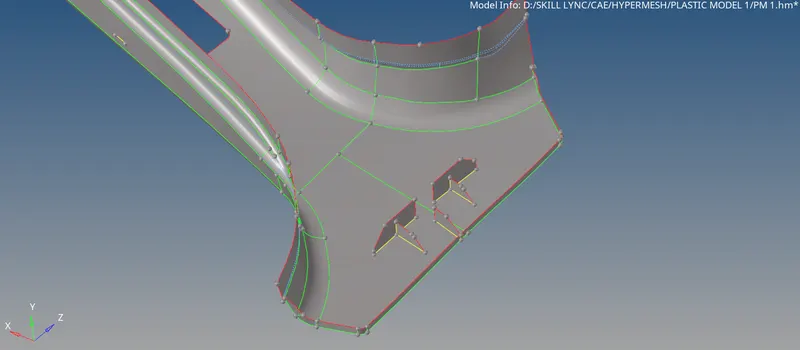
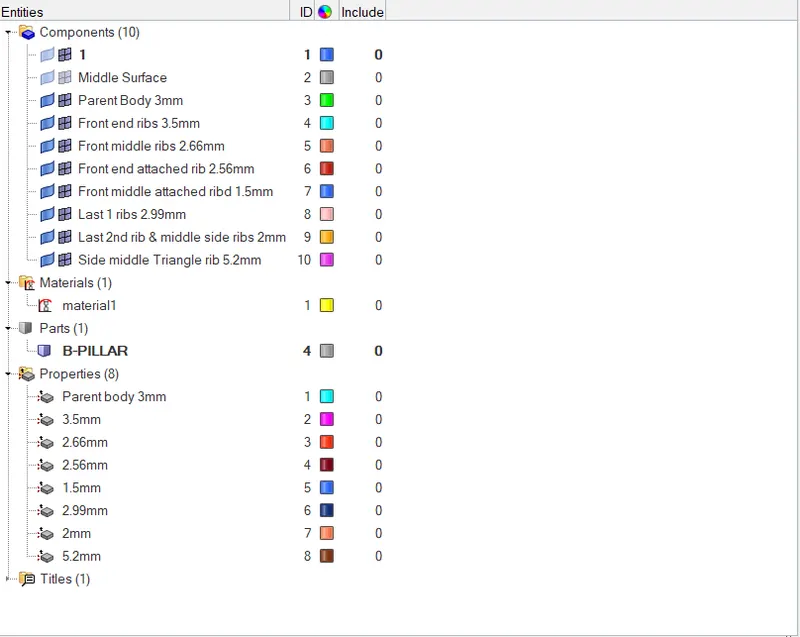
- The component is a B-Pillar with a number of ribs of varying thicknesses. Generate the mid-surface for the geometry by a suitable method. Manual mid-surface was used for mid-surface extraction.
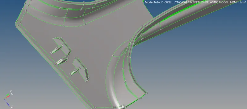
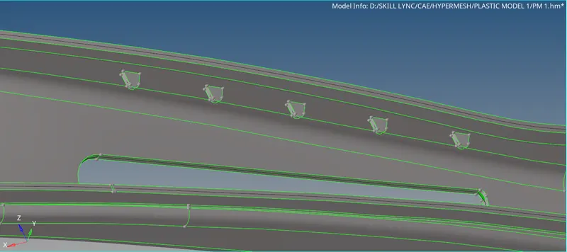
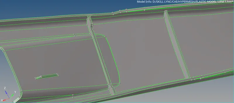
- The mid-surfaces generated were assigned their respective thickness by defining properties with correct thickness and then assigning these properties to the corresponding mid-surface component.
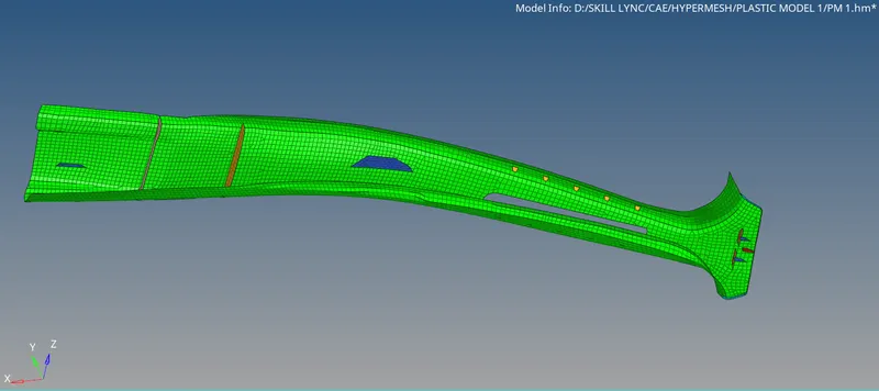
- The quality criteria were defined by pressing F10 on the keyboard and editing the settings.
- Now we have to mesh the Mid-surface generated. The automesh tool was used for this purpose. The target element length was set as 5 mm and the mid-surfaces were modeled using quad and tria elements.
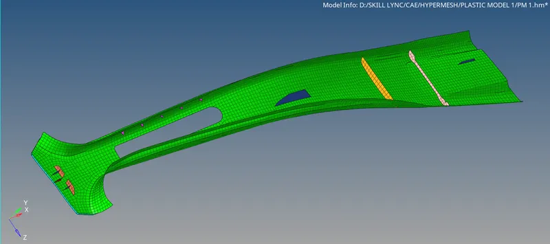
- Tria elements were avoided as far as possible. The mesh was cleaned for good quality. The element connectivity is also checked.
- To visualize the mesh with thickness, turn on the detailed 2d element representation option.
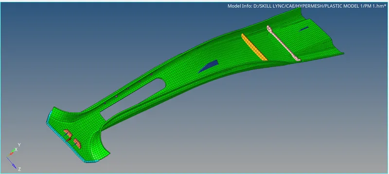
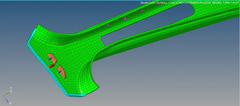
Result:
- The B-Pillar was modeled.
- The correct thicknesses were applied.
Learning Outcome:
- Midsurface generation for a component having a variable thickness.
- Assigning variable thickness to all the generated mid-surfaces.