Week 8 Multi cell Battery Pack
- Batteries used for EV and HEV applications are made up of long strings of cells in series in order to achieve higher operating voltages of 200 to 300 Volts
- They are more vulnerable.
- The problems can be compounded if parallel packs of cells are required to achieve the desired capacity or power levels. With a battery made up of n cells, the failure rate for the battery will be n times the failure rate of the individual cells.
- The performance of a battery pack is determined by finding out the weakest cell in the pack
- The weakest cell of a cell string dominates its capacity delivery is a fundamental physical property.
- A weak cell imposes constraints on charging and discharging of the battery pack
- A cell is labeled as weak when the SoC is different from the mean of SoC of other cells in a string.
- In general, cells in a battery pack can be connected in series or in parallel. The series connection of cells (i.e., a cell string) supplies a voltage that is the sum of individual cells. Cells connected in series have the same discharge current, and thus the weakest cell dominates their overall capacity delivery.
- It is not an essential criterion that a cell from the same batch has the same value of voltage limits and capacity.
-
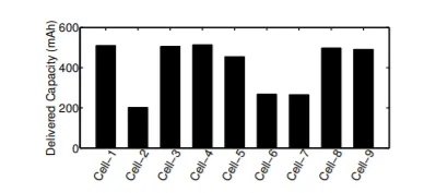
- The capacity of the weakest cell in the series string determines the overall pack capacity. In the presence of a weak cell in a pack, during charging, one or more cells will reach the maximum charge level before the rest of the cells in the series string. During discharge the cells that are not fully charged will be depleted before the other cells in the string, causing early Undervoltage shutdown of the pack.
- This can be demonstrated with an example, a research work carried out et al Liang He.
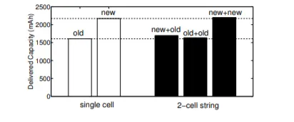
- A set of measurements is done with four off-the-shelf 2 300mAh cells— two of them have been in use over one year (and thus are weaker) and the other two are new (and thus are stronger).
- In the study, the cells are discharged at a 1 C rate. The cell combination of 2 new cells delivers 2171.3mAh capacity on whereas the combination of old cells delivers 1605.6 mAh. Further experiments are carried with the combination of form three 2-cell strings (i.e., new-and-old, old-and-old, and new-and-new) which are again discharged at a C rate of 1.
- The new and old string pair was giving the same capacity of two old. This is an indication that the string capacity is dominated by the weakest cell.
- The results of the study are represented below with help of a graph:
-
- The need for balancing:
-
When a lithium battery pack is designed using multiple cells in series, it is very important to design the electronic features to continually balance the cell voltages. This is not only for the performance of the battery pack but also for optimal life cycles. The use of cell balancing enables the design of a battery with a larger capacity for an application because balancing allows the battery to achieve a higher state of charge (SOC). If lithium cells are overheated or overcharged, they are prone to accelerated cell degradation. They can catch fire or even explode as a thermal runaway condition can occur if a lithium-ion cell voltage exceeds 4.2 V by even a few hundred millivolts. Cell balancing is the process of equalizing the voltages and state of charge among the cells when they are at a full charge. No two cells are identical. There are always slight differences in the state of charge, self-discharge rate, capacity, impedance, and temperature characteristics.
- Effects of imbalance on charging and discharging side:
- 1) Charging side- The weak cells in a string that has high internal resistance or lower capacity weak cells ( tend to exhibit higher voltage than the rest of the series cells at full charge termination. During charging these high voltage cells are further weakened by continuous overcharge cycles. The higher voltage of the weaker cells at charge completion causes accelerated capacity degradation. The degradation is somewhat exponential.If the maximal recommended charging voltage is exceeded even by as little as 10 percent, it will cause the degradation rate to increase by 30 percent.
- 2) Discharge-the weak cells tend to have lower voltage than the other cells, due to either higher internal resistance, or a faster rate of discharge that results from the lower capacity. This means that if any of the weak cells hit the cell under-voltage protection limit while the pack voltage is still sufficient to power the system, the full capacity of the battery will never be used as the pack protector will prevent over-discharge (which would damage the cell) by stopping the discharge of the whole pack when one cell voltage goes below the cell under-voltage threshold (usually around 2.7 V) capacity has a rapid decline after this lower limit. This is a case of underutilization of cells as a result of weak cell
- Cell balancing is of two types:
- 1) Passive-Only applicable when charging is done
- Passive cell balancing:
- The below circuit is a cell balancing circuit wherein a shunting resistor used to implement passive balancing. The balance is acheived by dissipating energy in the form of heat ( I^2*R). The current through resistor can be controlled via switch like a FET. A duty cycle can be used to control the FET. Zener diodes are also used
- While balancing is done the important factors taken into consideration are resistance sizing with balancing current and balancing time.
- Also, the thermals for heat dissipation need to evaluate to eliminate the degrading of the system.
- In general, the onboard passive balancing current ranges from a few hundreds of milliamperes to around 1 Ampere, hence the effective balancing time calculations heavily depend on balancing current. Also, the balancing current is directly proportional to cell voltage and hence it's not constant throughout the charge cycle.
- This adds to charging time
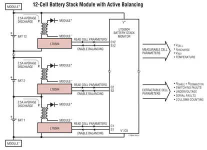
- 2) Active cell balancing, which utilizes capacitive or inductive charge shuttling to transfer charge between battery cells, is significantly more efficient because energy is transferred to where it is needed instead of being bled off in form of heat. Of course the trade-off for this improved efficiency is the need for additional components at higher cost.Applicable for both charge and discharge
- Active Cell Balancing During Discharge
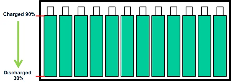
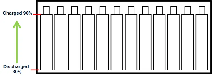
- The diagram below represents a battery stack with all cells at the starting possessing full capacity. The full capacity is mentioned as as 90% of charge because keeping a battery at or near its 100% capacity point for a longer time results in faster degradation of life. The fully discharged limit is contained at 30% represents fully discharged to prevent deep discharge of the cells.
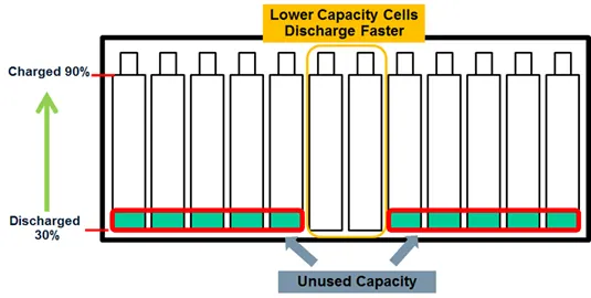
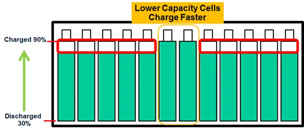
- Over the passage of time some cells become weaker than others as shown below.It can be seen that even though there may be quite a bit of capacity left in several batteries, the weak batteries limit the runtime of the system. It can be said that the weak restricts the complete utilization of batteries with higher capacity.
- A battery mismatch of 5% results in 5% of the capacity unused. With large batteries, this can be an excessive amount of energy left unused.
- This becomes critical in remote systems and systems that are difficult to access since it results in an increase in the number of battery charge and discharge cycles, which reduces the lifetime of the battery, leading to higher costs associated with more frequent battery replacement.
- With active balancing, the charge is bled from the stronger cells to the weaker cells, resulting in a fully depleted battery stack profile.
- The energy transfer can be from one cell to the whole battery, from the whole battery to one cell, or from
cell to cell. Each energy transfer is based on the type of dedicated DC-to-DC converter. The energy is
transferred from the strongest cell to the whole battery or other cells, and from the battery or other cells to
the weakest cell.
- Active Cell Balancing While Charging
- When charging the battery stack without balancing, the weak cells reach full capacity prior to the stronger batteries. Again it is the weak cells that are the limiting factor; in this case, they limit how much total charge our system can hold. The diagram below illustrates charging with this limitation.
- It is based on a circuit having inductors, capacitors,FET etc
-
The difference of two techniques can be visualized as below:
-
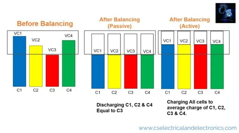
- Active cell balancing is costly but can be used during charging and discharging. It does not bled away extra charge in form of heat which is a loss.
- Sources:
- https://www.cselectricalandelectronics.com/what-is-active-and-passive-cell-balancing-why-cell-balancing-is-required/
- http://cse.ucdenver.edu/~helia/publications/CSR-eEnergy16.pdf
- https://www.researchgate.net/publication/283955435_Lithium-Ion_Battery_Cell-Balancing_Algorithm_for_Battery_Management_System_Based_on_Real-Time_Outlier_Detection