Simulation of a doorbell and automatic s witching of a fan when the temperature falls above 25°C
1. AIM
1.1 Make a Simulink model of Doorbell using solenoid block with the following details:
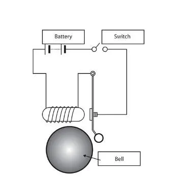
- a) In the below arrangement when the switch is closed the electromagnet receives electrical power from the battery so that the metal arm is pulled.
- b) The switch is closed for a period of 2 seconds and release. The physical movement of the plunger is observed.
1.2 A model where a thermistor to sense the temperature of a heater & turn on or turn off the fan as per the below conditions
- a) A temperature source has a varying temperature over a period of 50 sec, divided into three intervals:
- b) As 0 °C to 20 °C from 0 to 10 seconds, 27 °C from 10 to 30 seconds, 23 °C from 30 to 50 seconds.
- c) The fan becomes active when the temperature from the source is above 25 °C and is dormant otherwise.
2 ) OBJECTIVE
- a) Challenge part 1-Understand working of a solenoid through a doorbell model, simulate the same. Understand references used in Simulink like mechanical and electrical references. Usage of simscape models, function generator, and sensing elements.
- b) Challenge part 2-Undertsand how to use a temperature source, generate a signal in such a way that the same signal has various types of input over a time period. Understand switching actions for various conditions similar to that of a loop.
3) METHOD
3.1 Simulation of doorbell using solenoid block
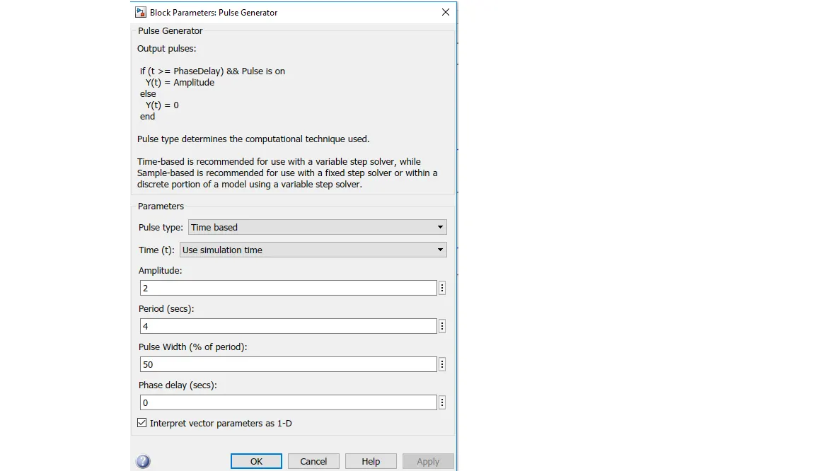
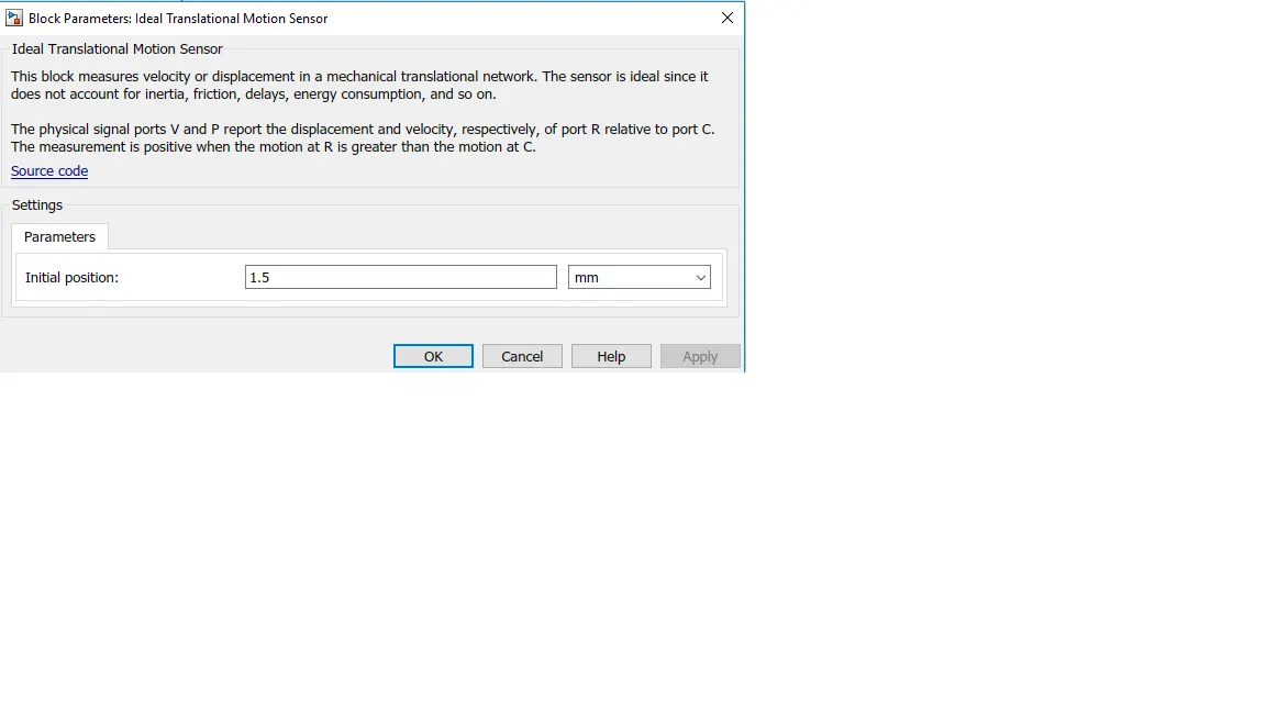
- Blocks used and value of input parameters to block. : Battery of nominal voltage-12V,Pulse generator,Simulink to ps convertor,Solenoid,Ideal translation motion sensor,solver configuration,Electrical and mechanical reference
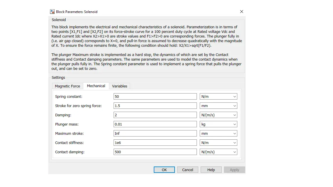
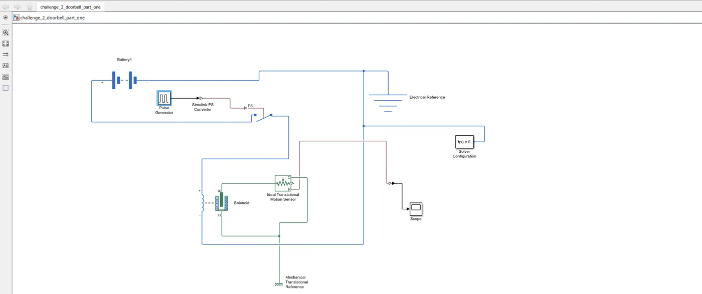
- Working of a Bell solenoid model- The core of a conventional doorbell is an electromagnet. Electromagnets is based on the principle that passing an electrical current through a wire creates a very small magnetic field around the wire. When the coils are in a state where it is wounded amplification of the magnetic field happens. This creates a substantial effect on any magnetic objects around it. Sound is produced in the doorbell upon activation and closing of the switch. Here in the place of an electromagnet source a solenoid is used which consists of a coil as mentioned, a plunger and a housing.The block is made in such a way that upon closing of the circuit via switch a sound is producedWhen the switch is closed the electromagnet receives power from the battery which in turn makes the metal arm to hit the bell and produce a sound
- Explainations of the system model and how it works
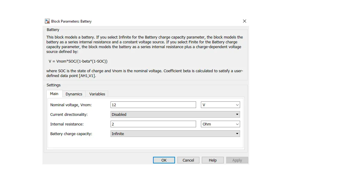
- a) A battery of 12V is used as a power source and creates an activation.
- b) The pulse generator is used to close the switch such that when a current is passed through and activation is initiated
- c) The pulse provided is time bases has an amplitude of 2 and a period of 4 sec with no phase delay
- d) All negative terminals is grounded to maintain a positive potential difference.
- e) The initial displacement for bell setup is set as zero meaning that the plunger is already in contact with a metal rod and any other value of displacement will result in moving it away from the bell thus, a displacement in a negative direction.
- f) When a current passes through upon closing of a switch upon which output is obtained sensed via a translational sensor.
- g) The model is constructed as below
-
3.2 Thermistor-Fan model simulation
- Blocks used and value of input parameters to block :Signal builder, Controlled temperature source,Voltage Sensor,Thermistor, resistor,Battery,solver configuration, thermal reference, Battery, electrical reference.
- The model should be developed in such a way that whenever the temperature is above 25 °C fan must be switched on
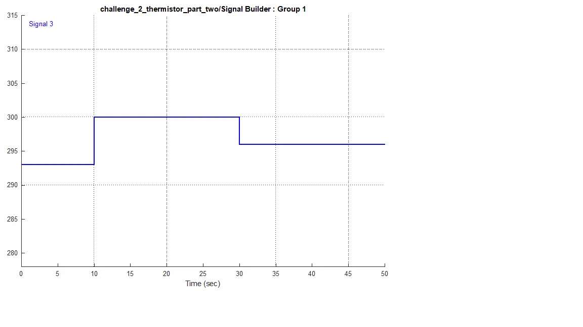
- A pulse generator is fed as input to a controlled temperature source. The pulse is modelled in such a way that over a period of 50 seconds the pulses are different in all three time intervals as 0 °C to 20 °C from 0 to 10 seconds, 27 °C from 10 to 30 seconds, 23 °C from 30 to 50 seconds.
- Say a voltage is fed as an input to port A of thermistor is senses the voltage and displays it. Inorder to make sure that the thermistor is kept to sense change in temperature the output from controlled temperature source is fed to it. The resistance of the thermistor changes as a result of temperature. Controlled temperature source receives input from signal builder which sends pulses as need that varies over three time intervals but remains constant during a specific interval
- Singal modeled in builder
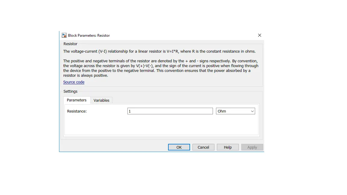
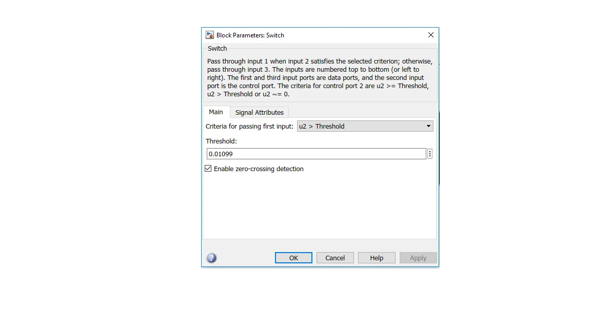
- Input parameters to blocks used:
-
-
- Explanation of block and how it works
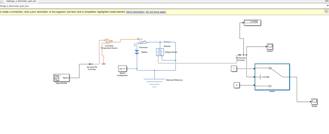
- a) Positive of the battery is connected to positive of the thermistor and negative is grounded
- b) Another resister is connected in series with the thermistor which serves as a reference and a voltage sensor is used to sense the drop in voltage across the combined subsystem ( thermistor and resistor).
- c) When a current flows and the temperature of the thermistor varies the voltage across the thermistor and resistor combination changes. As the temperature increases the voltage across the subsystem increases and decreases as the temperature decreases.
- d)This volattage acts as a threshold to activate the switch. It must be noted that the fan must be on only when temperature is above 25 °C and for any value of temperature less than these it must remain off. The voltage source help is determining the threshold voltage.
- e) Intially other than a signal builder the input to temperature source was given constant value of temperature above 25 to determine the threshold voltage that closes the circuit and runs the fan
- f) The switch works similar to an if loop it has three input ports one to which the output of voltage sensor which is the threshold value and others are given constant values of 1 and 0 via constant blocks when the value of output voltage is above the specified value set intitally it goes to 1 which means temperature is above 25 and fan is on else goes to zero and fan remains off. A display block is kept which shows the voltage that is threshold and keeps fan during required time.
- g) The model for block is below.
- 4)OUTPUT
- 4.1 Door bell
-
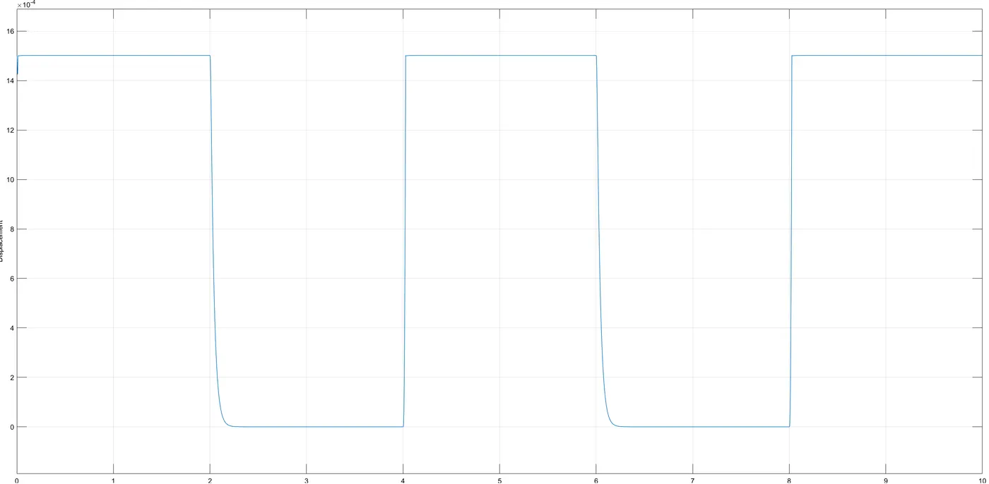
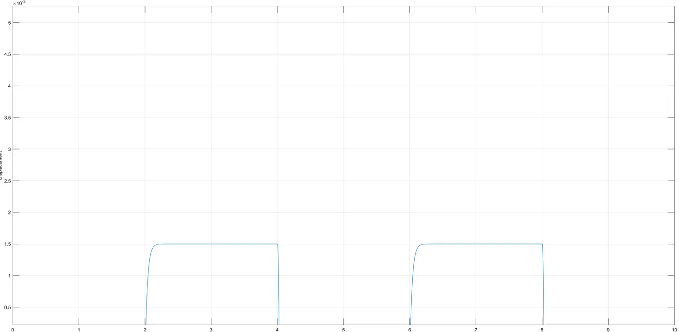
- Each cycle is of 4 seconds in which first two second there is sound and for next two no sound happens that is when the solenoid is activated. The plot is obtained by repeatedly changing the input parameters to mechanical characteristics of solenoid and well as displacement value in translational sensor. In the output there is a small delay which can be interpreted as the contact of plunger even after removing input. Inorder to a proper functioning of bell it must be noted that initial displacement is not zero.If its zero it means that the plunger is already in contact with the bell. Even a small change in input parameters such as mechanical properties of solenoid and initial displacement of translational motion sensor the output has a drastic change. Hence these values are set by iteration.
- 4.2 Thermistor fan model
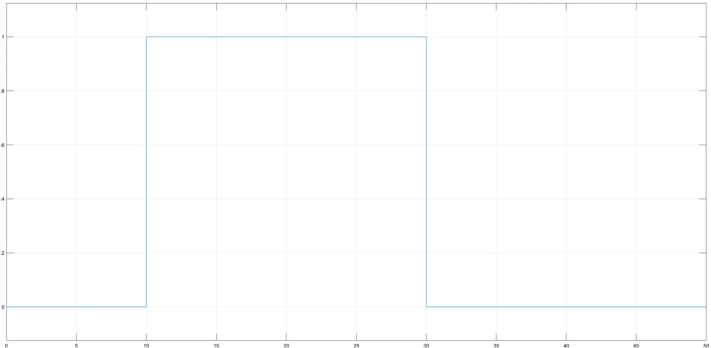
- From the output, it can be seen that for three temperature ranges of 20 °C from 0 to 10 seconds, 27 °C from 10 to 30 seconds, 23 °C from 30 to 50 seconds, Fan is on between 27 °C from 10 to 30 seconds where the temperature is more than 25°C. The switch which takes a threshold voltage of 0.01099 and when the threshold voltage is more than 1 it shows a block of the magnitude of 1 that is fed an input through a constant block. At all other times, it is inactive.
- 5) Inference
- The output of any simulation resembles real-time is primarily dependent on the input fed into each block used in the model. In order to obtain a simulation of a doorbell, a solenoid is needed which does the conversion of electrical energy into mechanical energy. A small delay occurs in the simulation due to a delay in response of the plunger. Every simscape model requires a solver configuration and for a current to flow all positive must be connected together and negative must be grounded. All electrical and mechanical components need a reference. Use of an if loop like switch helps to run the fan beyond a particular threshold value.
- 6) Error encountered
-
- This occurred as a result of setting the initial displacement of the translation sensor as 0 and improper mechanical parameters for the solenoid.