Week - 8 - Morphing
AIM
To create basic morphing techniques for the given components.
PROCEDURE
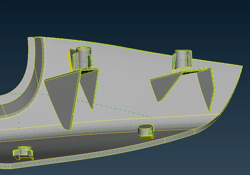
- First, the component is imported into ANSA. The component that will be morphed is shown in image below.
- To perform morphing actions, switch to Morph module.
- There are lot of tools to perform any given task.
- For box morphing, we first need to create a box volume around the geometry that needs to be morphed.
- To do so, got to Boxes>New>Ortho and 'New morph' window pops-up. Here,
- we can select the type of entities that needs to be selected and morphed and the type of box.
- As we only have a geometry model, geometry is selected as the entity type and Ortho as the box type.
- Then select the geometry and cofirm selection, to create a morph box around it, as shown in image below for the elliptical features on top,
- The box created has control points on its vertices, which are translated to change shape and size of the enclosed geometry.
- To translate the control points, go to Box morphing>move.
- Select the points that need to be translated and direction if required, then move the points freely in the specified directions.
- The image below shows the enclosed features height increased along the y-direction.
- The morph box can also be split into multiple sections to have more control points and therefore more control over the geometrical changes.
- To split the morph box, go to Boxes>split. Split tools allows a lot of options to split the box, like user, project, parametric, number, etc.
- Select the appropriate option and click on the box to split. The image below shows a box volume split using number option both horizontally and vertically.
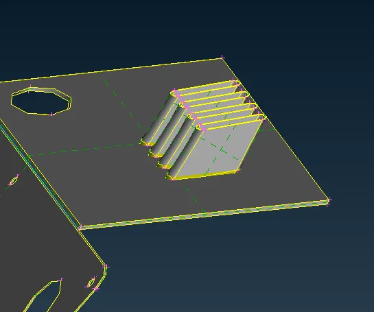
- Again, the control points are selected and moved using the move tool to achieve the desired shape, as shown in the image below.
- Similalry, some more changes are also made to the geometry. The final morphed geometry is shown below.
MORPHING
ANSA encompasses a full – fledged Morphing menu which is completely integrated with ANSA’s interface and doesn’t require any additional module installations or licenses. The functions of the Morphing menu can be used to efficiently re-shape both FE and/or Geometry based models.
Benefits and applications:
- Component and full system level FE/CFD models (such as automotive vehicle Crash, NVH and durability models) can be morphed to fit target design features such as styling lines, sections, proportions etc. precisely.
- Minimizes time in design modification by directly working at mesh level thus improves the overall lead time
- Creation of ‘n’ number of parameters for different designs, enabling easy trial and error method of design correction
- For the cases where, parametric CAD is not available or is not easily linked to the CAE, morphing softwares allow engineers to study parameterized changes in the attributes of vehicle geometry.
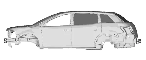
- In automatice industry morphing is commonly used for match styling, upper body to carry over under body matching, morphing sedan to station wagon or SUV etc. rapidly.
Conclusion:
Thus the basic morphing for the component is done. We also learnt about the advantages and applications of morphing.